
USB Extender Plus T - Switch Extron - Free user manual and instructions
Find the device manual for free USB Extender Plus T Extron in PDF.


| Type de produit | USB Extender Switch |
| Modèle | USB Extender Plus T |
| Marque | Extron |
| Dimensions (approx.) | 2.5 x 1.5 x 0.75 inches |
| Poids (approx.) | 0.2 lbs |
| Alimentation | 5V DC via USB host port |
| Connecteurs | USB Type-B (host), USB Type-A (device), RJ45 (extension) |
| Distance de transmission max | 100 m (328 ft) via CATx cable |
| Vitesse USB | USB 2.0 (High Speed) |
| Compatibilité OS | Windows, macOS, Linux |
| Fonctionnalités principales | Extension USB longue distance, transmission de signaux de périphériques |
| Entretien et nettoyage | Essuyer avec un chiffon doux et sec; éviter l'humidité |
| Sécurité | Ne pas exposer aux liquides; débrancher avant entretien |
| Pièces détachées | Non disponibles; appareil non réparable par l'utilisateur |
| Informations générales | Conçu pour une utilisation en intérieur; température de fonctionnement 0-40°C |
Frequently Asked Questions - USB Extender Plus T Extron
User questions about USB Extender Plus T Extron
0 question about this device. Answer the ones you know or ask your own.
Ask a new question about this device
Download the instructions for your Switch in PDF format for free! Find your manual USB Extender Plus T - Extron and take your electronic device back in hand. On this page are published all the documents necessary for the use of your device. USB Extender Plus T by Extron.
USER MANUAL USB Extender Plus T Extron
Go to www.extron.com for the complete user guide, installation instructions, and specifications before connecting the product to the power source.

The Extron® USB Plus Matrix Controller is a pre-configured controller that can easily be setup and deployed to control Extron USB Extender Plus products in a USB Matrix switching application within a gigabit Ethernet network. Quick and easy setup of the USB Plus Matrix Controller, USB Extender Plus transmitters and receivers is done using Extron Product Configuration Software (PCS). An Extron Control System or any third party control can interface with the USB Plus Matrix Controller via Ethernet or RS-232 to perform USB switching.
The main components in a USB Extender Plus Matrix system:
- USB Plus Matrix Controller — The controller is pre-configured to control the USB Extender Plus transmitters and receivers in a USB Matrix switching application. The default Telnet port is 22123 (see the USB Plus Matrix Controller Help File for full details).
- USB Extender Plus (transmitters and receivers) — At least 1 transmitter and 1 receiver are required, and up to 64 extenders total may be included. Each extender must be assigned a unique IP address (DHCP cannot be used to assign these addresses), and these addresses are uploaded to the USB Plus Matrix Controller. All twisted pair models are supported: rack mountable models (standard and HID-only), AAP™ models, and decorator-style models (see the USB Extender Plus Series User Guide, available on www.extron.com, for more information about these models).
- Product Configuration Software (PCS) — This free software is loaded on the computer and is used to configure the USB Extender Plus transmitters and receivers. It is also used to create a configuration that is uploaded to the USB Matrix Controller (see the USB Plus Matrix Controller Help File for details on how to use PCS with the USB Matrix Controller).
- Extron Toolbelt — This free software is used to configure the IP settings of the USB Matrix Controller (see the Toolbelt Help File at www.extron.com for details on how to use Toolbelt).
Installation
ATTENTION:
- Do not perform a Mode 5 reset (see USB Plus Matrix Controller Help File) to the USB Matrix Controller. Doing so will erase the factory loaded configuration used to control the USB Extender Plus transmitters and receivers.
The following diagram shows an example of a USB Plus Matrix Controller system setup:
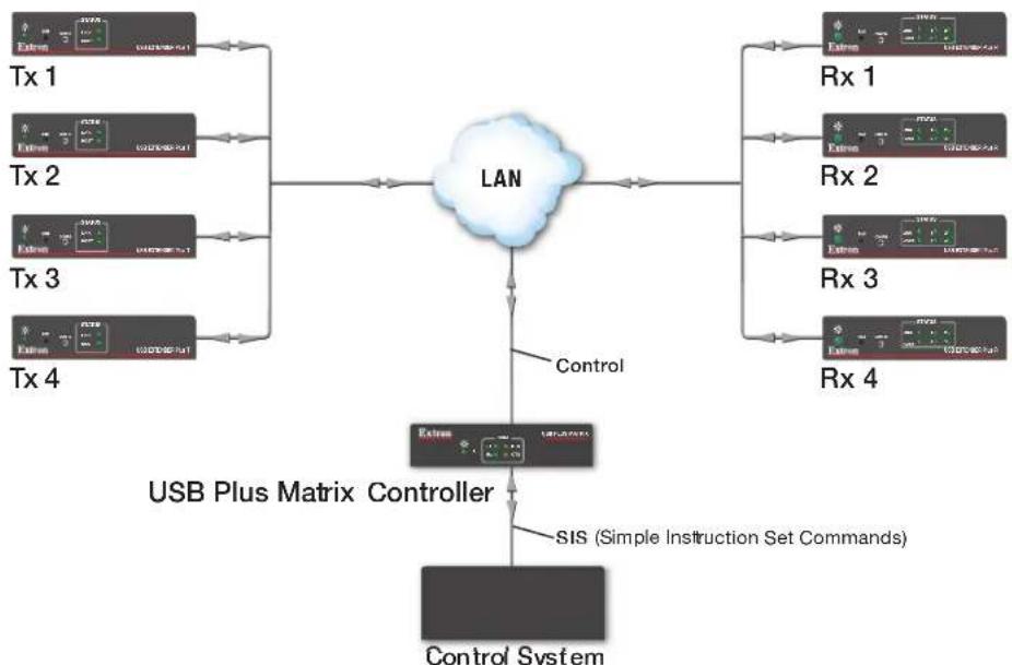
flowchart
graph TD
    A["Extrn 1"] --> D["LAN"]
    B["Extrn 2"] --> D
    C["Extrn 3"] --> D
    E["Extrn 4"] --> D
    D --> F["Control"]
    G["Extrn 1"] --> H["USB Plus Matrix Controller"]
    I["Extrn 2"] --> H
    J["Extrn 3"] --> H
    K["Extrn 4"] --> H
    H --> L["SIS (Simple Instruction Set Commands)"]
    M["Control System"] --> H
Figure 1. Application Diagram of the USB Plus Matrix Controller System
USB Plus Matrix Control • Setup Guide (Continued)
General Setup for the USB Extender Matrix System
NOTE: The USB Extender Matrix System must be configured in an isolated network before deployment. This reduces failed configurations.
- Enable the Network Pairing feature on each USB Extender transmitter and receiver to be used in the USB Matrix system.
- Use Extron Toolbelt to configure the IP settings of the USB Matrix Controller (IP, Subnet, and Gateway addresses).
NOTE: USB Extender Transmitters and Receivers must be on a static IP. Do not configure the extenders for DHCP mode. - Use PCS software and the included 9-pin to 2.5 mm TRS serial cable to sequentially configure each of the IP settings of the USB Extenders via the Config port of the product and create a USB Matrix Configuration.
- Use PCS software to upload the configuration of the USB matrix setup to the USB Plus Matrix Controller.
- Set up an (Extron) control system to control the matrix switching by making input and output ties. Use an Extron IPL control driver, available at www.extron.com.
Setup Requirements
The following are required for the USB Plus Matrix system setup:
• Download Toolbelt and PCS from www.extron.com —
• The computer running Toolbelt and PCS to configure the USB Matrix must be on the same Subnet and Gateway.
• USB Extender Plus transmitters and receivers (applies to all extenders in the system) —
- Must have a unique IP address (see the USB Plus Matrix Controller Help File).
NOTE: USB Extender Transmitters and Receivers must be on a static IP. Do not configure the extenders for DHCP mode.
- Must have over network pairing enabled (see the USB Extender Plus T/R User Guide).
- Must be on the same subnet and gateway as the controller and all other USB extenders in the system.
- Must have the same firmware as all other USB Extender Plus in the system.
• USB Plus Matrix Controller —
- Must use Extron Toolbelt to configure the IP, subnet and gateway address.
- Must be on the same subnet and gateway as the extenders.
- Must have an admin password assigned.
NOTE: The factory configured passwords for all accounts on this device have been set to the device serial number. In the event of a complete system reset, the passwords convert to the default, which is extron.
- Control System —
- An Extron or third party control system is required to interface and control the USB Matrix Controller to make and break ties between the USB Extender Plus transmitters and receivers.
• USB Plus Matrix Controller driver is available at www.extron.com.
Hardware Setup
To connect the devices:
- Connect the USB Plus Matrix Controller to the network via the LAN (TCP) RJ-45 port (see figure 2, ②).
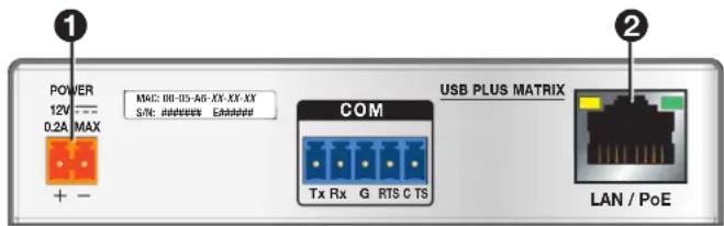
Figure 2. USB Plus Matrix Controller Rear Panel
- Connect power to the USB Plus Matrix Controller (①) and to the first USB extender that you will be configuring.
CAUTION: The wires must be kept separate while the power supply is plugged in. Remove power before wiring.
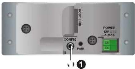
NOTE: Figure 3 shows the transmitter models only. However, on each receiver the Config port is at the same location as on the equivalent transmitter model.
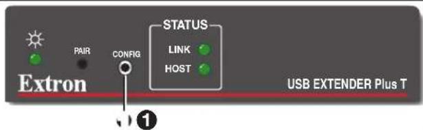
USB Extender Plus T/R (Rack-mountable), Front Panel
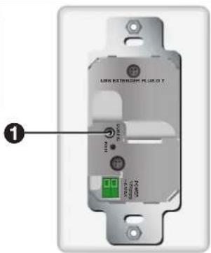
USB Extender Plus T/R D (Decorator-Style Wallplate), Rear Panel
USB Extender Plus T/R AAP, Rear Panel
Figure 3. Config Port Locations on the Three USB Extender Plus Models
Software Setup
PCS and Toolbelt are available free of charge at www.extron.com. Use PCS software to configure the USB extenders and upload their IP addresses to the USB Plus Matrix Controller controller. Use Extron Toolbelt to configure the IP settings of the USB Matrix Controller (see the USB Plus Matrix Controller Help File for details).
Dowloading the software
To obtain PCS and Toolbelt from the Extron website:
- Go to www.extron.com. On the main page, mouse over the Download tab (see figure 4, ①).
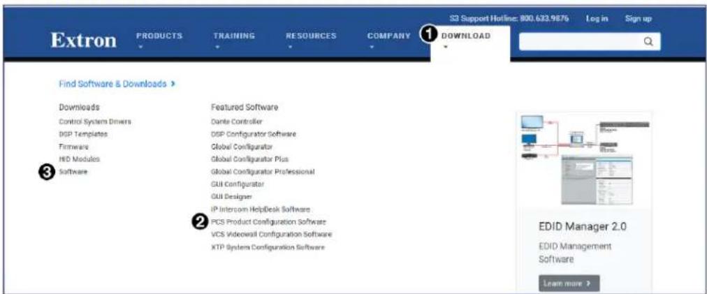
Figure 4. Download Page on Extron Website
- To download PCS, click PCS (②) in center column of the Find Software & Download screen.
USB Plus Matrix Control • Setup Guide (Continued)
- On the PCS page, click the Download button (see figure 5, 1). Follow the instructions on the subsequent screens to log in and download and install the software.
| Version | Release Date | New in the Current Release | Size | |
| 4.3.0 | Jul. 9, 2018 | - Added support for HC 403 - Added language support for Spanish, Simplified Chinese, Japanese, German, and French | 162.5 MB | ① Download Login required |
Figure 5. Download Button on the PCS Web Page
-
To download Toolbelt, click on the Software (see figure 4, ③ on page 3) in the left panel of the Download screen.
-
Scroll down to the alphabetic navigation bar (see figure 6).

Figure 6. Alphabetic Navigation Bar
- Click the T for Toolbelt, navigate to the Toolbelt software, and click Download (see figure 7, 1). Follow the instructions on the subsequent screens to log in and download and install the software.

Figure 7. Download Button for the Toolbelt Software
Starting Toolbelt
Before setting up a new Matrix Configuration, the network information of the USB Plus Matrix Controller must be configured in ToolBelt first.
To connect the USB Plus Matrix Controller with Toolbelt:
-
Right-click the Toolbelt icon (shown at right) that was placed on your desktop during software installation and select Run as Administrator. Toolbelt opens with the main window.
-
Click the Discovery button (see figure 8, ①) at the top of the window.
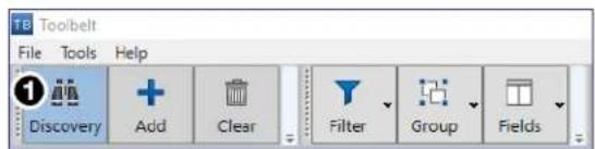

Figure 8. Discovery Button in Toolbelt
NOTE: If another application, such as PCS, is running a discovery, Toolbelt cannot run discovery at the same time.
- Navigate to the USB Plus Matrix Controller with the matching MAC address of the unit and double-click to connect (see figure 9, 1).
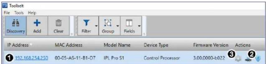
Figure 9. Navigate to USB Plus Matrix Controller
-
Select the icon ( ②) and configure:
-
IP address
- Subnet
- Gateway
NOTE: After configuration, the device may need to be located again with new IP address before selecting 📄.
-
Select the icon ( ③) to manage the device.
-
Select the Device Information tab and confirm the USBMAtrix_XX.gs program (see figure 10, ①) is loaded (X XX indicates the program version).
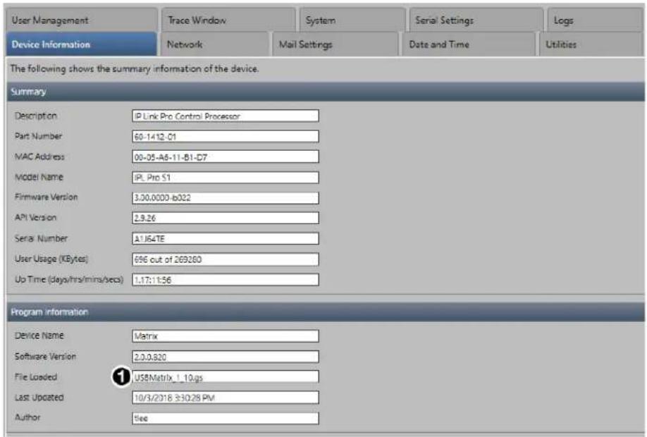
Figure 10. Device Information Tab
- Select the Network tab (see figure 11, ①) to confirm the network addresses are correctly configured.
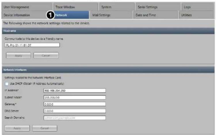
Figure 11. Network Tab
- Select the Utilities tab (see figure 12, ①).
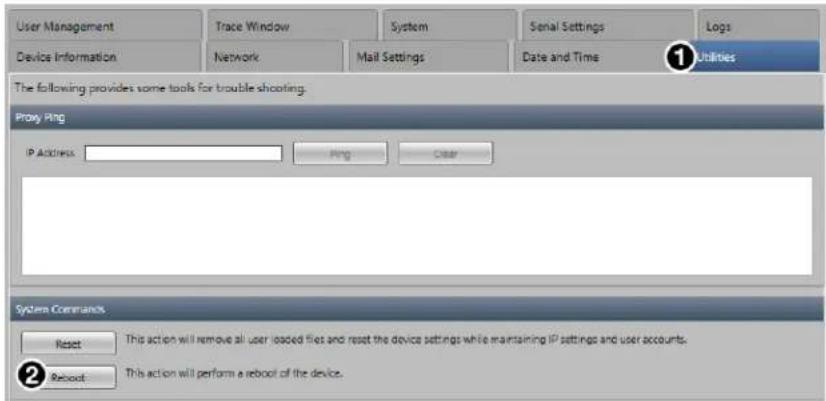
Figure 12. Utilities Tab
USB Plus Matrix Control • Setup Guide (Continued)
- Click the Reboot button (see figure 12, ② on page 5).
NOTE: A Reboot or power cycle is required after network settings have been changed to restart the USB matrix program.
- Close Toolbelt.
NOTE: If Toolbelt is running a discovery, another application, such as PCS, cannot run discovery at the same time.
Starting PCS
To get started using PCS to setup a new Matrix Configuration:
-
Double-click the Extron PCS icon (shown at right) that was placed on your desktop during software installation. The PCS opens with the main window.
-
From the File drop-down menu in the upper-left corner (see figure 13, ①), select New Configuration File.
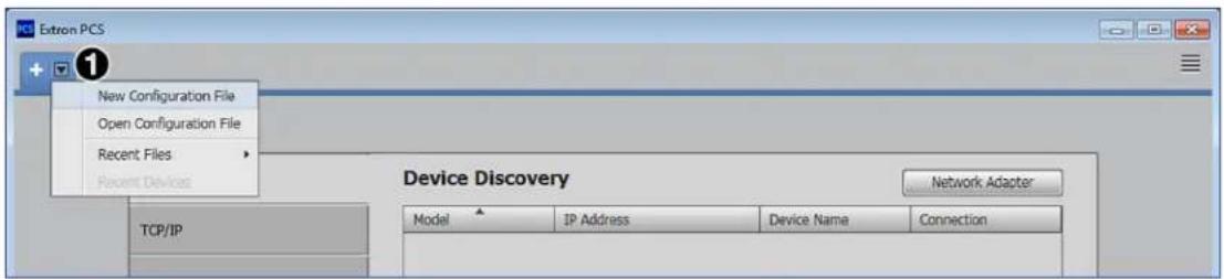
Figure 13. Selecting New Configuration File from the File Menu
The New Configuration File window opens (see figure 14).
- In the Device Models panel, scroll to locate USB Extender Matrix and select it (see figure 14, ①).
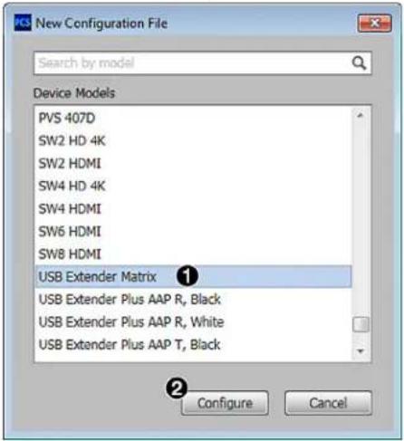
Figure 14. Device Models Panel
- Click the Configure button (②) at the bottom of the screen.
The Add + Configure Extenders screen is displayed (see figure 15 on page 7).
NOTES:
- On the bar across the top of the screen, 1. Extenders is highlighted (see figure 15, ①) to indicate that you are currently working on step 1, adding extenders to the configuration.
- Step through the prompts in the Hardware Wizard to configure the USB Extenders.
- A device tab is added above the bar, containing the words USB Extender Matrix (2). When the configuration has been saved, the name assigned to it appears on this tab. The tab also contains a drop-down list from which you can select to save the current configuration.
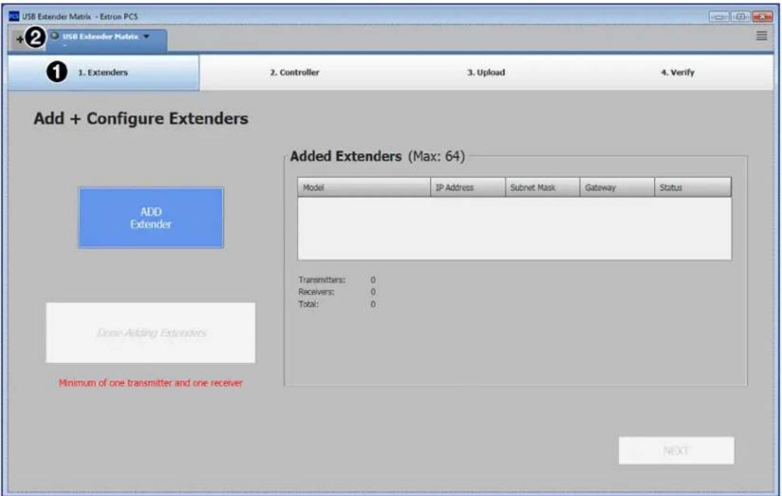
Figure 15. Add + Configure Extenders Screen
Creating configurations
To add, configure, and upload the USB extenders and the USB Plus Matrix Controller, and to create ties between the transmitters and receivers, see the USB Plus Matrix Controller Help File, provided with PCS (see Accessing the USB Plus Matrix Controller Help File).
NOTE: Each transmitter can be tied to no more than four receivers at a time.
Accessing the USB Plus Matrix Controller Help File
To open the USB Plus Matrix Controller Help File from within PCS:
-
Open the PCS program and start a new configuration.
-
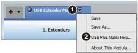
From the Device tab drop-down list (see image on the right, ①), select USB Plus Matrix Help (②). The USB Plus Matrix Controller Help File opens.
NOTES:
- When using a third-party controller it takes up to 10 seconds for changes, such as ties, to take effect or be reflected in PCS or control system.
- SIS commands sent to the USB Matrix Controller from a control system need at least 300 ms between commands, to ensure that commands are executed properly by the USB Matrix Controller.
Control TCP Connection
Up to 20 control TCP connections can be made to the USB Matrix Controller.
Replacing an Extender
If an extender that is part of the matrix malfunctions and needs to be replaced, follow these steps:
- Disconnect and remove the malfunctioning extender.
- Set the replacement extender to match the settings of the original extender:
• IP address, gateway address, and subnet mask
• Over-network pairing enabled (see the USB Extenders Plus T/R User Guide for more information).
-
Connect the extender to the network.
-
Connect power to the extender. When the extender is found, the configuration in the USB Matrix Controller is updated to include it.
USB Plus Matrix Control • Setup Guide (Continued)
Updating the CSV File
When new extender end points are added, the order of the extenders listed on the existing CSV file changes. Follow these steps to keep existing order:
- Download the existing CSV file (MatrixConfig.csv) using a third-party SFTP software. The CSV file is saved in the user space of the controller. Below is an example:
| TCP 22123 | |||||
| Subnet 255.255.255.0 | |||||
| Gateway 192.168.0.1 | |||||
| Serial 9600 | |||||
| USB Extender Firmware 1.00.00.17 | |||||
| Healing Retie Mode 1 | |||||
| T1 192.168.254.22 6137 00-05-a6-00-00-01 Name 1 60-1471-12 | |||||
| T2 192.168.254.23 6137 00-05-a6-00-00-02 Name 2 60-1471-12 | |||||
| T3 192.168.254.24 6137 00-05-a6-00-00-03 Name 3 60-1471-12 | |||||
| T4 192.168.254.25 6137 00-05-a6-00-00-04 Name 4 60-1471-12 | |||||
| R1 192.168.254.26 6137 00-05-a6-00-00-05 Name 5 60-1471-13 | |||||
| R2 192.168.254.27 6137 00-05-a6-00-00-06 Name 6 60-1471-13 | |||||
| R3 192.168.254.28 6137 00-05-a6-00-00-07 Name 7 60-1471-13 | |||||
| R4 192.168.254.29 6137 00-05-a6-00-00-08 Name 7 60-1471-13 | |||||
- Add new or update existing end point information.
- Save the CSV file as MatrixConfig.csv.
- Using third-party SFTP software, load the CSV file back onto the controller.
Troubleshooting
The USB Plus Matrix Controller can easily be setup and deployed to control Extron USB Extender Plus products in a USB Matrix switching application within a gigabit Ethernet network. In the event that the matrix is not functioning properly, follow these guidelines to troubleshoot the issue.
Verify the following:
- Network router and switch or switches have been configured correctly, are powered, and are compatible with the specs of the USB Extenders and USB Plus Matrix Controller.
• Network twisted pair cables are properly terminated and functioning.
• USB Extenders and the USB Plus Matrix Controller are powered and connected to the network.
• PCS on your computer is v4.0 at a minimum.
• USB Extenders, USB Plus Matrix Controller, and PC with PCS are on the same subnet mask and gateway. - USBMatrix_ X_XX.gs (X_XX is the program version) is loaded on the USB Plus Matrix Controller via Toolbelt.
-
USB Plus Matrix Controller has firmware v2.05.000 b-007 at a minimum via Toolbelt.
• A correct username and password have been entered for USB Plus Matrix Controller. The defaults are: -
username: admin
• password: serial number (see NOTE below)
NOTE: The factory configured passwords for all accounts on this device have been set to the device serial number. In the event of a complete system reset, the passwords convert to the default, which is extron.
The following ports are open —
- 22123 — Allows the USB Plus Matrix Controller to be interfaced with a control system. If using DataViewer, this port allows troubleshooting and querying controller information.
• 22022 — Allows user space access on the USB controller in order to access the CSV file, and if need be SFTP.
• Pairing and unpairing between transmitters (Tx), receivers (Rx), PCS, and controller occurs in TCP/IP layer 3 and UDP.
- USB data transfer between the Tx and Rx that occurs in MAC address layer 2 and UDP.
SISTM (Simple Instruction Set) Commands
This section describes the SIS commands that can be issued from the computer or control system to the USB Plus Matrix Controller via RS-232 or LAN connection (Default Telnet port is 22123). You can also enter commands using an application such as the Extron DataViewer, available at www.extron.com (see the DataViewer Help File to use this program). The RS-232 port uses a protocol of 9600 baud, 8 data bits, 1 stop bit, no parity, and no flow control. SIS commands consist of one or more characters per field. No special characters are required to begin or end a command sequence. When the USB Plus Matrix Controller determines that a command is valid, it executes the command and sends a response to the host device. All responses from the controller to the host end with a carriage return and a line feed (CR/LF = ←), indicating the end of the response character string (one or more characters).
Error Responses
When the controller receives a valid command, it executes the command and sends a response to the host device. If the unit is unable to execute the command because the command contains invalid parameters, it returns an error response to the host.
E01 — Invalid input number
E10 — Invalid command
E12 — Invalid output number
E13 — Invalid value
E14 — Invalid command for this configuration
E95 — Configuration file does not exist.
E96 — Transmitter is offline.
E97 — Receiver is offline.
E98 — Maximum number of receivers are tied to the transmitter.
E99 — No configuration loaded
Using the Command and Response Table
The Command and Response Table for SIS Commands, beginning on the next page, lists the commands that the controller recognizes as valid, the responses that are returned to the host, a description of the command function or the results of executing the command, and some examples of the command syntax in ASCII.
NOTE: Unless otherwise stated, upper- and lowercase text can be used interchangeably in the commands.
| ASCII to HEX Conversion Ta ble | Esc 1B | CR ∅D | LF ∅A | |||||||
| Space 20 | ! | 21 | " | 22 | # | 23 | $ 24 | % 25 | & 26 | ' 27 |
| ( 28 ) | 29 | * | 2A | + | 2B | , | 2C | - 2D | . 2E | / 2F |
| ∅ 30 | 1 | 31 | 2 | 32 | 3 | 33 | 4 | 34 | 5 35 | 6 36 |
| 8 38 | 9 | 39 | : | 3A | ; | 3B | < 3C | = 3D | > 3E | ? 3F |
| @ 40 | A | 41 | B | 42 | C | 43 | D | 44 | E 45 | F 46 |
| H 48 | I | 49 | J | 4A | K | 4B | L | 4C | M 4D | N 4E |
| P 50 | Q | 51 | R | 52 | S | 53 | T | 54 | U 55 | V 56 |
| X 58 | Y | 59 | Z | 5A | [ | 5B | \ 5C] | ] 5D | ^ 5E | _ 5F |
| ` 60 | a | 61 | b | 62 | c | 63 | d | 64 | e 65 | f 66 |
| h 68 | i | 69 | j | 6A | k | 6B | I | 6C | m 6D | n 6E |
| p 70 | q | 71 | r | 72 | s | 73 | t | 74 | u 75 | v 76 |
| x 78 | y | 79 | z | 7A | { | 7B | I | 7C} | 7D | ~ 7E |
Symbol Definitions
• = Space
← = Carriage return with line feed
← or | = Carriage return with no line feed
Esc or W = Escape
^95 = Superscripts indicate the error message displayed if the command is entered incorrectly or with invalid parameters (see Error Responses above).
X1 = Input (transmitter) number
X2 = Output (receiver) number
X3 = Starting output tie number when viewing all ties
X4 = Firmware version number ( n.nn)
X5 = Connection status of USB Extender Plus
0 = offline
1 = online
(-) = not configured
x6 = Extender connection status
0 = offline
1 = online
2 = unknown device
X8 = Healing behavior (after extender replacement)
0 = untie (ties to replaced extender remain broken)
1 = maintain ties (ties to extender are recreated)
X9 = Endpoint number where healing occurred
X10 = Results of saving a configuration to file 0 = failed (error in writing the configuration file) 1 = successful (configuration saved to file)
X11 = Number of TCP connections
Response is three digits, padded with zeros.
12 - 15 Serial connection parameters: 12 = baud rate, 13 = Parity, 14 = Data bits, 15 = Stop bits
X16 = IP address ( nnn.nnn.nnn.nnn)
X17 = MAC address ( XX-XX-XX-XX-XX-XX)
X18 = Hostname of the host device
x19 = Port timeout in seconds
X20 = Configuration reloading result code
0 = error reloading CSV (system configuration) files
1 = reload successful
2 = error restarting matrix
3 = error stopping matrix
4 = CSV file not found
X21 = Extender endpoint name assigned in the configuration file. If no name is assigned, the response is None.
X22 = Clear ties at startup setting
0 = do not clear ties at startup
1 = clear ties at startup
X23 = Matrix input size
X24 = Matrix output size
X25 = Time on host device: Www, · DD Mmm · yyyy · HH:MM:SS ( Www=day of the week, Mmm=month )
USB Plus Matrix Control • Setup Guide (Continued)
Command and Response Table for SIS Commands
| Command | ASCII Command (Host to Controller) | Response (Controller to Host) | Additional Description |
| NOTE: The USB Plus Matrix Controller is set to verbose mode 3, which cannot be changed to any other verbose mode. All query responses are sent out to all connected TCP clients and serial port connections. | |||
| Configuration File Management | |||
| Reload configuration | EscRELOAD← | RELOAD X20← | Reload the current configuration. X20is the reload result. |
| KEY: X20 = Configuration reloading result code: 0 = error reloading CSV (system configuration) files, 1 = reload successful, 2 = error restarting matrix, 3 = error stopping matrix, 4 = CSV file not found | |||
| Ties | |||
| View all ties | Esc0*X3 *1VC← | Vgp00•outX3* X1* X1* X1* X1* X1*...* X1* Vid← | View all ties, starting with output X3 in the configuration. Up to 16 ties can be displayed. X3 = the number of the first tie that the response will start with. |
| View output tie status | X2! OUT | X2·INX1·ALL← | |
| Break all ties | 0*! | Remove all existing input-output ties. | |
| Example: | 0*! OUT | X2·IN00·ALL← | Response varies: if any ties exist, a response for each one that gets removed will appear. |
| Make tie | X1*X2! OUT | X2·INX1·ALL← | Create a tie between input X1 and output X2. |
| Break a tie | 0*X1! OUT00·IN | X1·ALL← | |
| Set Clear all ties on startup | EscCLEAR*X22← | CLEAR*X22← | Set whether or not to clear all ties when the system is started (X22). |
| View Clear all ties on startup | EscCLEARVC← | CLEAR*X22← | View current setting for Clear all ties on setup. |
| KEY: X1 = Input numberX2 = Output numberX3 = Starting output tie number when viewing all tiesX22 = Clear All Ties on Startup setting: 0 = Do not clear all ties (default), 1 = Clear all ties at startup. | |||
| Information Requests | |||
| Query firmware version | Q Ver01* | X4← | View firmware version X4 |
| Query part number | N Pno | 56-002-000001← | View software part number. |
| Query input and output size | I Info00*USB | X23*X24← | These values represent the size of the matrix. |
| KEY: X4 = Firmware version (displayed with two decimal places)X23 = Input sizeX24 = Output size | |||
| USB Extender Plus Connection Status | |||
| View input connection status Example: | EscCONNI← | CONNIX51X52...X5← | View connection status X5 of the USB Plus inputs. A matrix configured with inputs 1, 3, and 6. All extenders are online. |
| View output connection status Example: | EscCONNO← | CONNOK51X52...X5← | View connection status X5 of the USB Plus outputs. A matrix configured with outputs 2 and 5. All extenders are online. |
| Device input status changed (Unsolicited) | CONNIX1*X6← | X6 is device status. | |
| Device output status changed (Unsolicited) | CONNOK2*X6← | X6 is device status. | |
| KEY: X1 = Input numberX2 = Output numberX3 = Connection status of USB Extender Plus: 0 = offline, 1 = online,(-) = not configuredX6 = Extender connection status: 0 = offline (not connected), 1 = online (connected), 2 = unknown device | |||
| Healing Behavior (when an extender is replaced) | |||
| Set healing behavior | EscHEALING*X8← | HEALX8← | Set the system behavior to X8 when an extender is replaced in the configuration. |
| View healing behavior | EscHEALVC← | HEAL X8← | View the set system behavior X8 when an extender is replaced in the configuration. |
| Force healing check | EscHEALNOW← | FORCED← | Force the system to perform a healing process. |
| Healed endpoint (unsolicited) | HEALED*X5*X9← | Shows the connection status X5 and number of the endpoint X9 at which healing occurred. | |
| KEY: X5 = Connection status of USB Extender Plus: 0 = offline, 1 = online, (-) = not configuredX8 = System response (healing behavior) when an extender is removed from the configuration:0 = Untie (Ties are not restored to the replaced extender.)1 = Maintain existing ties (Ties that were made to the removed unit are restored to the replacement extender.)X9 = Number of endpoint at which healing occurred. | |||
| IP and Serial Information | |||
| View serial port parameters | Esc|CP← | Cpn001·CcpX12,X13,X14,X15← | View the serial port parameters X12 (baud rate), X13 (parity), X14 (data bits), X15 (stop bits). |
| View IP address | EscCI← | Ipi·X16← | View IP address X16 of the unit (mmn.nmn.nmn.nmn). |
| View MAC address | EscCH← | Iph·X17← | View hardware Media Access Code (MAC) address X17 of the unit (xx.xx.xx.xx.xx.x). |
| View total TCP connections | EscCC← | IccX11← | View the total number (X11) of TCP connections. |
| View hostname | EscCN← | Ipn·X18← | View hostname X18 of the host device. |
| KEY: X11 = Number of current TCP connections. Response is three digits, padded with zeros.X12 = Baud rate (default = 9600)X13 = Parity (default = no parity)X14 = Data bits (default = 8)X15 = Stop bits (default) = 1)X16 = IP address (nnn.nnn.nnn.nnn)X17 = MAC address (xx.xx.xx.xx.xx.xx)X18 = Hostname of host device. If DHCP is off, the IP address of the host device is returned. | |||
| Global Timeout | |||
| Set global timeout | Esc|*X19TC← | Pti1*X19← | Set port timeout X19 (in 10-second increments). |
| View global timeout | Esc|TC← | Pti1*X19← | View port timeout X19. |
| View controller time | EscCT← | Ipt-X25← | View date and time X25 set on the host device. |
| KEY: X19 = Port timeout: 1 (10 seconds) through 6500 (65000 seconds). Default = 30 (300 seconds = 5 minutes)X25 = Time on host device: Www, * DD Mmm* yyyy* HH:MM:SS(WWW= day of the week, Mmm= month) | |||
| Endpoint Name | |||
| View extender input name | EscENAME*I*X1← | ENAME*I*X1*X21← | View name X21 of input X1 . |
| View extender output name | EscENAME*O*X2← | ENAME*O*X2*X21← | View name X21 of output X2. |
| KEY: X1 = Input numberX2 = Output numberX21 = Name given in configuration file for endpoint at input X1 and output X2None = no name given in the configuration file | |||
Power Supply Attention Notices
For information on safety guidelines, regulatory compliances, EMI/EMF compatibility, accessibility, and related topics, see the Extron Safety and Regulatory Compliance Guide on the Extron website.
- Installation
- ATTENTION:
- USB Plus Matrix Control • Setup Guide (Continued)
- General Setup for the USB Extender Matrix System
- Setup Requirements
- Hardware Setup
- Software Setup
- Dowloading the software
- Starting Toolbelt
- Starting PCS
- NOTES:
- Creating configurations
- Accessing the USB Plus Matrix Controller Help File
- Control TCP Connection
- Replacing an Extender
- Updating the CSV File
- Troubleshooting
- SISTM (Simple Instruction Set) Commands
- Error Responses
- Using the Command and Response Table
- Symbol Definitions
- Power Supply Attention Notices
Brand : Extron
Model : USB Extender Plus T
Category : Switch