
GV-AS1010 - Access Control System Geovision - Free user manual and instructions
Find the device manual for free GV-AS1010 Geovision in PDF.


| Product Type | Access Control System |
| Brand | Geovision |
| Model | GV-AS1010 |
| Dimensions (approx.) | 200 x 150 x 50 mm |
| Weight (approx.) | 0.5 kg |
| Power Supply | 12V DC, 1A |
| Supported Card Types | 125kHz EM, 13.56MHz Mifare |
| Number of Users | Up to 10,000 |
| Number of Events Log | Up to 50,000 |
| Communication | RS-485, TCP/IP |
| Relay Output | 2 relays (door lock, alarm) |
| Inputs | 2 (door sensor, exit button) |
| Operating Temperature | -10°C to 50°C |
| Humidity | 0% to 85% (non-condensing) |
| Enclosure Material | ABS plastic |
| Protection Rating | IP54 |
| Main Functions | Card access, keypad PIN, anti-passback, time schedules |
| Maintenance | Clean with a dry, soft cloth. Do not use solvents. |
| Safety Features | Tamper alarm, emergency unlock, power failure memory |
| Spare Parts | Replacement card readers, power supplies available |
| Repairability | Modular design; main board and reader separately replaceable |
| General Information | 228-page user manual available in PDF |
Frequently Asked Questions - GV-AS1010 Geovision
User questions about GV-AS1010 Geovision
0 question about this device. Answer the ones you know or ask your own.
Ask a new question about this device
Download the instructions for your Access Control System in PDF format for free! Find your manual GV-AS1010 - Geovision and take your electronic device back in hand. On this page are published all the documents necessary for the use of your device. GV-AS1010 by Geovision.
USER MANUAL GV-AS1010 Geovision
natural_image
Exterior view of a GEVSICAN industrial control module with multiple connected modules and a digital payment terminal (no visible text or symbols)Before attempting to connect or operate this product, please read these instructions carefully and save this manual for future use.

GeoVision Inc
© 2015 GeoVision, Inc. All rights reserved.
Under the copyright laws, this manual may not be copied, in whole or in part, without the written consent of GeoVision.
Every effort has been made to ensure that the information in this manual is accurate. GeoVision, Inc. makes no expressed or implied warranty of any kind and assumes no responsibility for errors or omissions. No liability is assumed for incidental or consequential damages arising from the use of the information or products contained herein. Features and specifications are subject to change without notice.
Note: No memory card slot or local storage function for Argentina.
GeoVision, Inc.
9F, No. 246, Sec. 1, Neihu Rd.,
Neihu District, Taipei, Taiwan
Trademarks used in this manual: GeoVision, the GeoVision logo and GV series products are trademarks of GeoVision, Inc. Windows and Windows XP are registered trademarks of Microsoft Corporation.
April 2015
Contents
Welcome...... vii
Important Notes for Maintaining Power Supply...... viii
Elevator Control....x
Optional Devices xi
Installation Considerations...... xiii
Firmware and Software Compatibility ....xiv
Definition....xv
1. GV-AS100 / 1010 Controller .... 1
1.1 Introduction....2
1.1.1 Main Features....4
1.1.2 Packing List....5
1.1.3 GV-AS100 / 1010 Board Layout....6
1.2 Installation....7
1.2.1 Connecting Card Readers....8
1.2.1.A Wiegand Readers (GV-AS100 Only) 8
1.2.1.B RS485 Readers 9
1.2.1.C Network Readers (GV-AS1010 Only)....10
1.2.2 Connecting Input Devices 11
1.2.3 Connecting Output Devices....12
1.2.4 Connecting the PC....14
1.2.4.A Connecting GV-AS100 to PC....15
1.2.4.B Connecting GV-AS1010 to PC....16
1.2.4.C Switches (GV-AS100 Only) 17
1.2.5 Connecting the Power....17
1.2.6 Fitting the Battery....18
1.2.7 Using the Function Keys (GV-AS1010 Only)....19
1.3 Programming Mode....20
1.3.1 Quick Reference of Programming Table....22
1.3.2 Adding and Deleting a Card 24
1.3.2.A Adding a Card....24
1.3.2.B Deleting a Card....25
1.3.3 Resetting the APB Function 25
1.3.4 Accessing the Security Mode 26
1.3.4.A Enabling the Security Mode....26
1.3.4.B Disabling the Security Mode 26
1.3.5 Setting Parameters ......27
1.3.6 Displaying System Information....29
1.3.7 Restoring Factory Defaults....30
1.4 Web-Based Configurations ......31
1.5 GV-AS100 / 1010 Specifications ....32
2. GV-AS110 / 1110 Controller .... 34
2.1 Introduction....35
2.1.1 Main Features....37
2.1.2 Packing List....38
2.2 Installation....39
2.2.1 Connecting Card Readers....41
2.2.1.A Wiegand Readers (GV-AS110 Only) 41
2.2.1.B Network Readers (GV-AS1110 Only) 41
2.2.2 Connecting Input Devices 42
2.2.3 Connecting Output Devices....43
2.2.4 Connecting to the PC 45
2.2.4.A Connecting GV-AS110 to PC....45
2.2.4.B Connecting GV-AS1110 to PC....46
2.2.5 Connecting the Power....47
2.3 Programming Mode....48
2.3.1 Adding and Deleting Cards ....48
2.3.1.A Adding a Card....49
2.3.1.B Deleting a Card....50
3.2 Programming the GV-AS110 / 1110....51
2.4 LED Status and Beeper 54
2.5 Web-Based Configurations ....56
2.6 GV-AS110 / 1110 Specifications....57
3. GV-AS120 Controller 59
3.1 Introduction....60
3.1.1 Main Features....62
3.1.2 Packing List....62
3.2 Installation....63
3.2.1 Connecting a Wiegand Reader 64
3.2.2 Connecting Input Devices 64
3.2.3 Connecting Output Devices....65
3.2.4 Connecting to the PC....66
3.2.4.A RS-485 Connection 66
3.2.4.B Network Connection....68
3.2.5 Connecting the Power....68
3.3 Programming Mode....69
3.3.1 Adding and Deleting Cards 69
3.3.1.A Adding a Card....70
3.3.1.B Deleting a Card....70
3.4 LED Status and Beeper 71
3.5 Web-Based Configurations .....72
3.6 GV-AS120 Specifications....73
4. GV-AS210 / 2110 Controller 74
4.1 Introduction....75
4.1.1 Main Features....75
4.1.2 Packing List....75
4.2 Installation....77
4.2.1 Connecting Card Readers....77
4.2.1.A Wiegand Readers....77
4.2.1.B RS-485 Readers....78
4.2.2 Connecting Input Devices 79
4.2.3 Connecting Output Devices....80
4.2.4 Connecting Backup Battery....81
4.2.5 Connecting the Power....81
4.2.6 Connecting the PC....82
4.2.7 Fitting the Battery (GV-AS2110 Only)....83
4.3 Other Settings....84
4.3.1 Web Setting Switch....84
4.3.2 Resetting the GV-AS210 / 2110....84
4.3.3 Restoring Factory Defaults....85
4.4 The Web Interface....86
4.5 GV-AS210 / AS2110 Specifications 87
5. GV-AS410 / 4110 / 810 / 8110 Controller 88
5.1 Introduction....89
5.1.1 Main Features....89
5.1.2 Packing List....90
5.2 Installation....92
5.2.1 Connecting Card Readers....92
5.2.1.A Wiegand Readers....92
5.2.1.B RS-485 Readers....93
5.2.2 Connecting Input Devices 95
5.2.3 Connecting Output Devices....96
5.2.4 Connecting Backup Battery....97
5.2.5 Connecting the Power....97
5.2.6 Connecting the PC....98
5.3 Other Settings....99
5.3.1 Web Setting Switch....99
5.3.2 Resetting the GV-AS410 / 4110 / 810 / 8110....99
5.3.3 Restoring Factory Defaults....100
5.4 GV-AS410 / 4110 / 810 / 8110 Kit (Optional)....101
5.4.1 Packing List....101
5.4.2 Overview....101
5.4.3 Connecting the GV-AS410 / 4110 / 810 / 8110 Kit....102
6.4.4 GV-AS410 / 4110 / 810 / 8110 Kit Specifications ....104
5.5 The Web Interface....105
5.6 GV-AS410 / 4110 / 810 / 8110 Specifications....106
6. GV-EV48 Controller 107
6.1 Introduction....108
6.1.1 Main Features....108
6.1.2 Packing List....108
6.2 Installation....110
6.2.1 Connecting RS-485 Card Readers....110
6.2.2 Connecting Output Relay....111
6.2.3 Connecting Backup Battery....112
6.2.4 Connecting the Power....112
6.2.5 Connecting the PC....113
6.3 Other Settings....114
6.3.1 Web Setting Switch....114
6.3.2 Resetting the GV-EV48....114
6.3.3 Restoring Factory Defaults....115
6.4 The Web Interface....116
6.5 GV-EV48 Specifications....117
7. Installing on a Network 118
7.1 Fixed IP Connection....120
7.2 DHCP Connection....122
7.2.1 Connection over LAN....122
7.2.2 Connection over Internet....125
8. The Web Interface...... 128
8.1 Basic Settings....130
8.1.1 System Setup....130
8.1.2 Upgrading Firmware....132
8.1.3 Changing Login ID and Password....133
8.2 Advanced Settings....134
8.2.1 Function Configuration....136
8.2.2 Parameter Configuration....139
8.2.2.A GV-AS1010 / 1110 / 210 / 2110 / 410 / 4110 / 810 / 8110....139
8.2.2.B GV-EV48....143
8.2.3 Card Configuration....145
8.2.4 Card Information 146
8.2.5 Time Configuration....147
8.2.6 Input Configuration....149
8.2.7 Output Configuration....152
8.2.7.A Output Function Settings 154
8.2.7.B Output Condition Settings....155
8.2.8 Wiegand Configuration....157
8.2.9 Function Key Configuration....158
8.3 Extended Device....159
8.3.1 Extended Reader 159
9. Optional Devices 163
9.1 Optional GV-ASBox 164
9.1.1 Main Features....164
9.1.2 Packing List....164
9.1.3 GV-ASBox Board Layout....165
9.1.4 Installation....166
9.1.4.A Connecting GV-AS100 / 110 / 120....166
9.1.4.B Connecting a Wiegand Reader....167
9.1.4.C Connecting GV-Readers and GV-GF Fingerprint Readers .....168
9.1.4.D Connecting Input Devices....169
9.1.4.E Connecting Output Devices....170
9.1.4.F Connecting Backup Battery....172
9.1.4.G Other Settings....173
9.1.4.G.a Web Setting Switch....173
9.1.4.G.b Resetting the GV-ASBox 173
9.1.4.G.c Restoring Factory Defaults....173
9.1.5 GV-ASBox Specifications....174
9.2 Optional GV-ASNet....175
9.2.1 Main Features....175
9.2.2 Packing List....175
9.2.3 GV-ASNet Overview 176
9.2.4 Installation....177
9.2.4.A Connecting GV-AS100 / 110 / 120....177
9.2.4.B Connecting GV-Readers and GV-GF Fingerprint Readers .....178
9.2.4.C Connecting Backup Battery....179
9.2.4.D Other Settings 180
9.2.4.D.a Web Setting Switch....180
9.2.4.D.b Restoring Factory Defaults....180
9.2.4.D.c Power Status LED....180
9.2.5 GV-ASNet Specifications 181
9.3 Web Interface through Optional Devices....182
9.3.1 Basic Setting....182
9.3.2 Advanced Settings....183
9.3.2.A Function Setting....184
9.3.2.B Parameter Setting....187
9.3.2.C Status Monitor....191
9.3.2.D Card Information....192
9.3.2.E Time Setting 193
9.3.2.F In/Out Function....194
9.3.2.G Extended Reader 201
- Troubleshooting 203
Appendix 209
A. GV-MountA900 for GV-AS110 / 1110 (Optional)....210
Welcome
This user manual includes the following types of GV-AS / GV-EV Controllers:
GV-AS Controllers
| Doors Supported | Page Number | ||
| One-Way Control | Two-Way Control | ||
| GV-AS100 / 1010 | 1 | 1 | See |
| GV-AS110 / 1110 | 1 | 1 | See |
| GV-AS120 | 1 | 1 | See |
| GV-AS210 / 2110 | 4 | 2 (Wiegand only)4 (Wiegand + RS-485 / Network) | See p. 74 |
| GV-AS410 / 4110 | 4 | 4 | See |
| GV-AS810 / 8110 | 8 | 4 (Wiegand only),8 (RS-485 / Network) | See p. 88 |
GV-EV Controllers
| Floors Supported Readers Supported | Page Number | ||
| GV-EV48-24 Floors | 24 | 2 (RS-485 or Network) See p.107 | |
| GV-EV48-48 Floors | 48 | ||
Important Notes for Maintaining Power Supply
To make sure GV-AS / EV Controllers can function properly during a power outage, be sure to replace the internal battery on the controllers when needed. It is also recommended to install a backup battery for compatible GV-AS Controllers.
Refer to the following sections for instructions on how to install a backup battery:
■ GV-AS100 / 110 / 120 through GV-ASBox: See 9.1.4.F Connecting Backup Battery.
■ GV-AS100 / 110 / 120 through GV-ASNet: See 9.2.4.F Connecting Backup Battery.
■ GV-AS210 / 2110: See 4.2.4 Connecting Backup Battery.
■ GV-AS410 / 4110 / 810 / 8110: See 5.2.4 Connecting Backup Battery.
■ GV-EV48: See 6.2.3 Connecting Backup Battery.
The table below lists the types of internal batteries used by different GV-AS / EV Controllers.
| Type of Battery GV-AS / EV Controllers | |
| Replaceable Button Cell | GV-AS100 / 2110 / 4110 / 8110 |
| Built-in Battery | GV-AS1010 / 110 / 1110 / 120 / 210 / 410 / 810GV-EV48 |
Replaceable Button Cell (GV-AS100 / 2110 / 4110 / 8110)
For GV-AS100 / 2110 / 4110 / 8110, you can replace the battery on your own when you see low battery messages and icons in GV-ASManager.
![ASManager - [Event Monitor] File Monitoring View Setup Personnel Language Tools Window Help Controllers 16c16 Controller Status Alarm Forced Open Duress Tamper Fire Alarm Held Open Tailgating Urgent Code 2: Door 2 Card Mode 3: Door 3 Card Mode 4: Door 4 Card Mode AS400 1: Door 1 Card Mode 2: Door 2 Card Mode 3: Door 3 Card Mode Alarm Monitor Access Monitor Event Monitor Info 4 X Message Door Local Time Reset Door 2 3/18/2014 4:38:55 PM Reset Door 3 3/18/2014 4:38:55 PM Reset Door 4 3/18/2014 4:38:55 PM Low Battery AS400 3/18/2014 4:38:55 PM Reset Door 1 3/18/2014 4:38:56 PM Reset Door 4 3/18/2014 4:38:56 PM Low Battery AS400 3/18/2014 4:38:56 PM Lists Ready Operator: 1 3/18/2014 4:42:39 PM](/content/2026/05/1004733/images/05303bd0be45980a828d8bde137e3a126b2b94561bbc52587aa500050615aef9.jpg)
Note: Make sure the plastic insulation film under the battery is removed when using GV-AS100 / 2110 / 4110 / 8110 for the first time. The low battery messages and icons will appear if the plastic film is not removed.
Built-in Battery (GV-AS1010 / 110 / 1110 / 120 / 210 / 410 / 810 & GV-EV48)
When the controller runs out of battery, the local time on the controller will be reverted back to 1999/12/31. The controller time can be found on the Web interface of the controller on the Time Configuration page and in the Access Monitor / Alarm Monitor / Event Monitor of GV-ASManager.
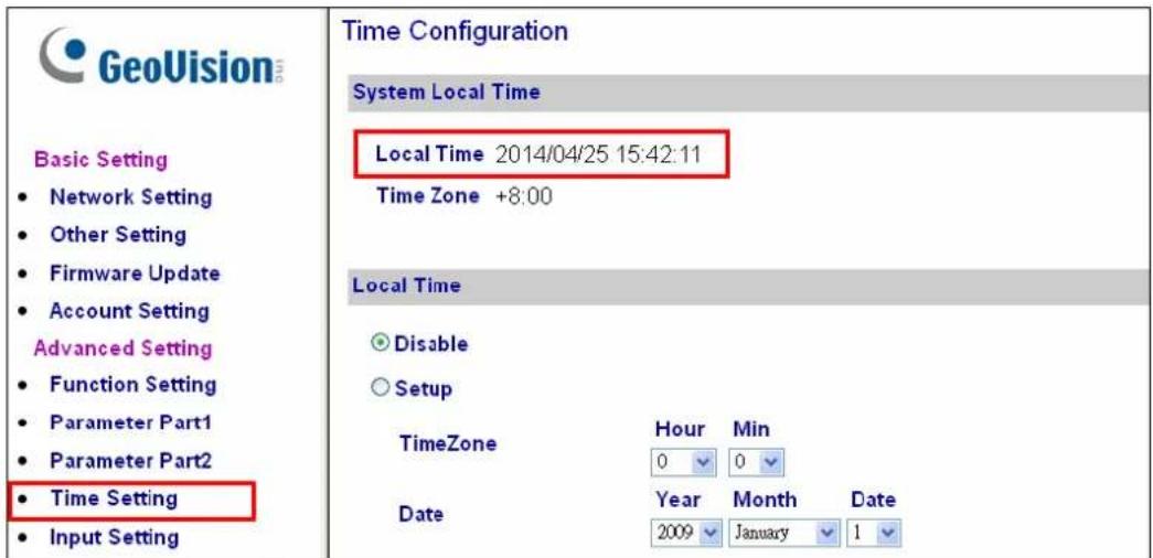
When you see the controller year shown as 1999 or 2000, disconnect the controller from power and reconnect it to power. If the year is still shown as 1999 or 2000, the controller battery needs to be replaced. When this occurs, connect the controller to a backup battery and maintain connection with GV-ASManager at all times. When connected to GV-ASManager, the controller's time will be synchronized with GV-ASManager's time.
Elevator Control
GV-AS / GV-EV Controllers provide two types of elevator control.
For GV-AS100 / 1010 / 110 / 1110 / 120 / 210 / 2110 / 410 / 4110 / 810 / 8110, the GV-AS Controller can control access to the elevator call buttons. Users who present the correct identification card to the elevator reader will be able to use the elevator and can go any floors. The output relays are connected to the call button of the elevator.
For GV-EV48, a controller especially designed for elevator control, access can be granted to specific floors. You can configure each identification card to specify the floors it can access. In this type of elevator control, each output relay is connected to the button of corresponding floor in the elevator control panel.
Optional Devices
Optional devices can expand the capabilities and versatilities of your GV-AS / GV-EV
Controllers. Consult your sales representative for more information.
| GV-Reader 1251 | GV-Reader 1251 is a card reader that uses a 125 kHz frequency. It has both Wiegand and RS-485 outputs that can be connected to any standard access control panel. |
| GV-Reader 1352 V2 | GV-Reader 1352 V2 is a card reader that uses a 13.56 MHz frequency. It has both Wiegand and RS-485 outputs that can be connected to any standard access control panel. |
| GV-RK1352 | GV-RK1352 is a card reader with keypad that uses a 13.56 MHz frequency. The reader has both Wiegand and RS-485 outputs that can be connected to any standard access control panel. |
| GV-R1352 | GV-R1352 is a card reader that uses a 13.56 MHz frequency. The reader has both Wiegand and RS-485 outputs that can be connected to any standard access control panel. |
| GV-GF Fingerprint Reader | The reader supports three operation modes: Fingerprint Only, Fingerprint + Card and Card Only. In Fingerprint Only mode, the fingerprints are enrolled through GV-ASManager. In Fingerprint + Card mode, the fingerprint templates are stored on the user card. In Card Only mode, the users only need to swipe the card to be granted access. Readers with optical and capacitance sensors are available. |
| GV-CR420 | GV-CR420 is a card reader with a built-in 4MP wide angle IP camera. The card reader recognizes identification cards and transmits live view through network connection. |
| GV-DFR1352 | The GV-DFR1352 is a card reader designed to be installed on the door frame for recognizing identification cards. Featured with the Wiegand and RS-485 outputs, the unit can be connected to any standard access control panel. |
| GV-ASBox | Only works with GV-AS100 / 110 / 120. The device can add Network function, 1 Wiegand interface, 8 additional inputs and outputs to GV-AS100, GV-AS110 and GV-AS120. |
| GV-ASNet | Only works with GV-AS100 / 110 / 120. This device can add Network function to GV-AS100, GV-AS110 and GV-AS120. |
| GV-Hub | Only works with GV-AS100 / 110 / 120. GV-Hub can convert the standard RS-232 signal of up to 4 controllers to RS-485, allowing the controllers to connect to computers. |
| GV-COM | Only works with GV-AS100 / 110 / 120. GV-COM can convert the standard RS-232 signal of one controller to RS-485, allowing the controller to connect to a computer. |
| GV-Net / IO Card | Only works with GV-AS100 / 110 / 120. GV-Net / IO Card can convert the standard RS-232 signal of one controller to RS-485, allowing the controller to connect to a computer. |
| GV-AS410 / 4110 / 810 / 8110 Kit | Only available for GV-AS410 / 4110 / 810 / 8110. Includes a GV-AS410 / 4110 / 810 / 8110, a power adapter board, a power supply and a casing for backup battery. The power supply provides power to the controller and up to 8 output devices (12V, 0.9A per device). |
| Cabinet | Only available for GV-AS410 / 4110 / 810 / 8110 and GV-EV48. With the cabinet, GV-AS / GV-EV Controllers can be mounted directly to a wall or recessed into the wall. Two types of cabinet dimensions are available (W x H x D): ·383.5 x 443.5 x 112.2 mm / 15.1 x 17.5 x 4.4 in ·300 x 420 x 86 mm / 11.8 x 16.5 x 3.4 in |
| GV-MountA900 | Only available for GV-AS110 / 1110. GV-MountA900 is a mounting plate that allows you to attach GV-AS110 / 1110 to a US single gang power box. ·Dimensions: 100 x 68 mm / 3.9 x 2.7 in ·Weight: 55 g / 0.12 lb |
| Push Button Switch | The push button switch can be integrated with access control system, allowing door exit by momentarily activating or deactivating the electric locking device. Both American standard and European standard push buttons are available. |
| GV-IB25 / 65 / 85 Infrared Button | The GV-IB25 / 65 / 85 Infrared Button detects infrared movement within 3 to 12 cm and allows you to open the door with a wave of hand. |
| Electric Lock | Three types of electric locks are available: electromagnetic lock, electric bolt and electric strike. |
| GV-AS ID Card & GV-AS ID Tag | GV-AS ID Cards and GV-AS ID Tags are ideal for business and residential environment, where access control is important for security reasons. 125 kHz and 13.56 MHz cards and tags are available. |
Installation Considerations
- There are distance limitations for Wiegand and RS-485 communications. Please note:
- Wiegand interface:
Recommended Wiegand cable: Wiegand cable (a twisted pair of 24 AWG wires)
- 100 meters (328.1 feet) for GV-AS2110 / 4110 / 8110
- 30 meters (98.43 feet) for other GV-AS Controllers
• RS-485 interface: 600 meters (1968.50 feet)
Recommended RS-485 cable: standard 485 cable (a twisted pair of 24 AWG wires)
-
GV-ASManager software is used to manage GV-AS / GV-EV Controllers. There is a limit for the number of controllers connected to GV-ASManager based on communication modes.
-
Through network connection, up to 1000 GV-AS / GV-EV Controllers can connect to GV-ASManager.
- Through RS-485 connection, up to 16 GV-AS100 / 110 / 120 Controllers can connect to the same COM port on a computer running GV-ASManager.
- When presenting cards to GeoVision readers and the built-in readers of GV-AS100 / 1010 / 110 / 1110 / 120, make sure only one card is presented at a time to avoid frequency interference.
Note: For GV-AS100 / 2110 / 4110 / 8110, it is highly recommended to replace the button cell battery included on the circuit board annually.
Firmware and Software Compatibility
The GV-AS / GV-EV Controllers firmware versions compatible with GV-ASManager V4.0 - V4.3 are listed below.
| GV-ASManager | |||||||
| Models | V4.0 | V4.1 | V4.2 | V4.2.1 | V4.2.2 | V4.2.3 | V4.3 |
| GV-AS100 | V1.06 | V1.08 | |||||
| GV-AS110 / 120 | V1.06 | V1.07 | |||||
| GV-AS1010 / 1110 | N/A | V1.0 | |||||
| GV-AS410 | V1.1 | V1.2 | V1.22 | V1.23 | |||
| GV-AS210 / 810 | V1.1 or earlier | V1.2 | V1.22 | V1.23 | V1.3 | ||
| GV-AS2110 / 4110 / 8110 | N/A | V1.23 | |||||
| GV-EV48 | N/A | V1.0 | V1.1 | V1.11 | V1.12 | V1.3 | |
| GV-ASBox / GV-ASNet(Optional devices) | V1.06 | V1.07 | |||||
V1.3
Definition
| Tampering Alarm | GV-AS100 / 1010 / 110 / 1110 / 120 have built-in sensors to detect whether the controller is being physically tampered with (i.e. opening of the controller or sustaining strong impact). For GV-AS210 / 2110 / 410 / 4110 / 810 / 8110, the tampering alarm sensor needs to be installed separately and the triggering conditions depend on the type of sensor installed.The GV-AS Controller also provides output relays for activating and deactivating electric lock, siren and emergency door release when tampering is detected by the sensors.For configuring input sensors and outputs, see Chapter 9 The Web Interface or Web Interface through Optional Devices in Chapter 10 for GV-AS100 / 110 / 120.For settings of alarm conditions see Step 2: Configuring the Doors in Chapter 4 of GV-ASManager User's Manual. |
- GV-AS100 / 1010 Controller
1.1 Introduction
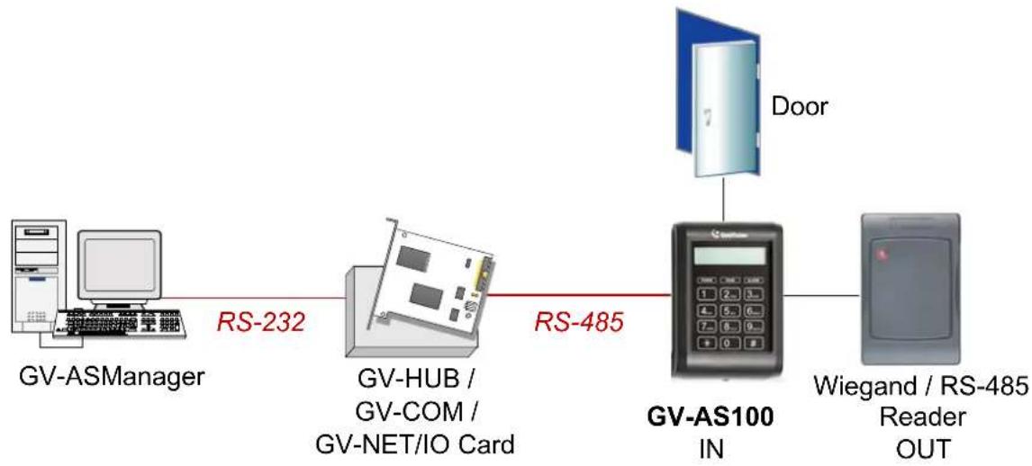
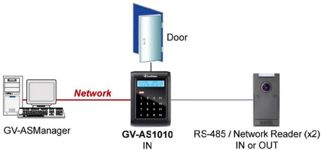
GV-AS100 / 1010 is a single door controller with a built-in a card reader and a LCD display.
You can connect one more card reader to GV-AS100, and up to two more card readers to GV-AS1010 for entry and exit applications. GV-AS100 / 1010 has the capability to store up to one thousand cards as a standalone model and up to 40,000 cards when connected to GV-ASManager. The programming is either done on the keypad or from the software GV-ASManager.
GV-AS100 / 1010 is suitable for controlling doors, parking gates and access to elevator call buttons.
flowchart
graph LR
    A["GV-ASManager"] -->|RS-232| B["GV-HUB / GV-COM / GV-NET/IO Card"]
    B -->|RS-485| C["GV-AS100 IN"]
    C --> D["Door"]
    C --> E["Wiegand / RS-485 Reader OUT"]
flowchart
graph LR
    A["GV-ASManager"] -->|Network| B["GV-AS1010 IN"]
    B --> C["RS-485 / Network Reader (x2) IN or OUT"]
    D["Door"] --> B
    B --> E["Display: 1 2 3 F1 4 5 6 F7 7 8 9 F10"]
Figure 1-1
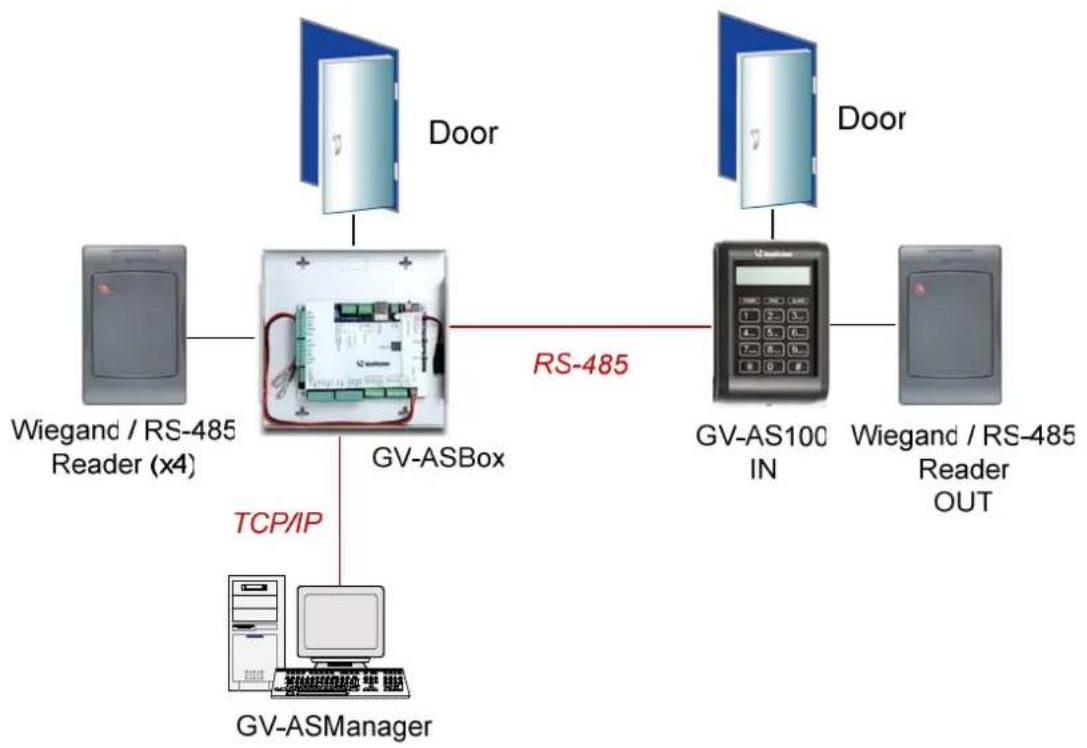
GV-AS100 can make network connection to GV-ASManager using the optional GV-ASBox or GV-ASNet. With GV-ASBox, two-door control is also possible as illustrated below.
flowchart
graph TD
    A["Door"] --> B["Wiegand / RS-485 Reader (x4)"]
    B --> C["GV-ASBox"]
    C --> D["RS-485"]
    D --> E["GV-AS100 IN"]
    E --> F["Wiegand / RS-485 Reader OUT"]
    C --> G["TCP/IP"]
    G --> H["GV-ASManager"]
Figure 1-2 Through GV-ASBox
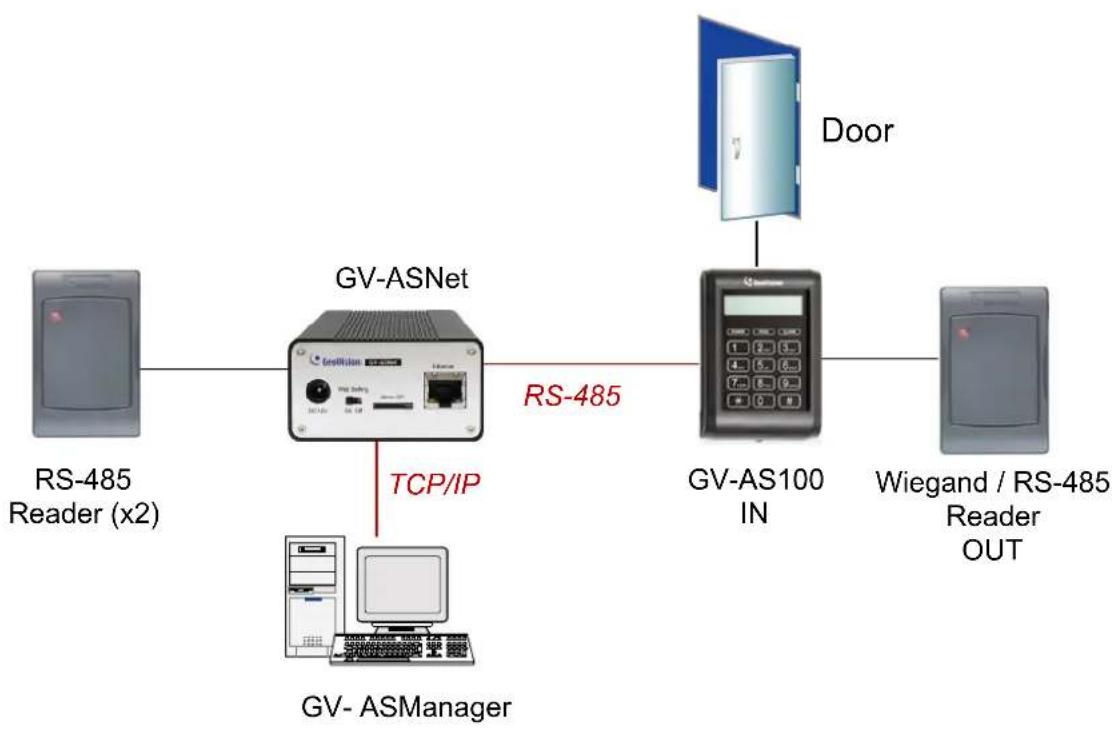
flowchart
graph LR
    A["RS-485 Reader (x2)"] --> B["GV-ASNet"]
    B -->|TCP/IP| C["GV-ASManager"]
    B --> D["GV-AS100 IN"]
    D --> E["Door"]
    E --> F["Wiegand / RS-485 Reader OUT"]
Figure 1-3 Through GV-ASNet
1.1.1 Main Features
GV-AS100
- 1 door (one-way and two-way control), expandable to 2 doors with optional GV-ASBox
• 1,000 / 40,000 cards (standalone / networked or RS-485 mode) - Easy programming from keypad
• Built-in 3 digital inputs and 2 relay outputs - 1 Wiegand output (26 \~ 64 bits) and 1 RS-485 interface for extra reader programming
• Built-in 13.56 MHz Reader
• Built-in tampering alarm sensor
• IP54-compliant housing
• Anti-Passback (APB) support
GV-AS1010
• 1 door (one-way and two-way control)
• 1,000 / 40,000 cards (standalone / networked mode)
- Easy programming from keypad
- Function keys on keypad to register attendance data for GV-TAWeb
• Built-in 3 digital inputs and 2 relay outputs
• 1 RS-485 interface for connecting to up to 2 readers
• 1 network interface for connection with GV-ASManager and TCP/IP reader
• Built-in 13.56 MHz Reader
• Built-in tampering alarm sensor
• IP54-compliant housing
• Anti-Passback (APB) support
1.1.2 Packing List
GV-AS100
GV-AS100
• Power Adaptor 12V DC / 1A
- Power Cord
- Screw x 3
- Screw Anchor x 2
- Master Card
• GV-AS ID F Card x 20
- Software CD
GV-AS1010
GV-AS1010
• Power Adaptor 12V DC / 1.25A
- Screw x 3
- Screw Anchor x 2
- Enroll Card
- Delete Card
• GV-AS ID F Card x 20
- Torx Wrench
- Software CD
1.1.3 GV-AS100 / 1010 Board Layout
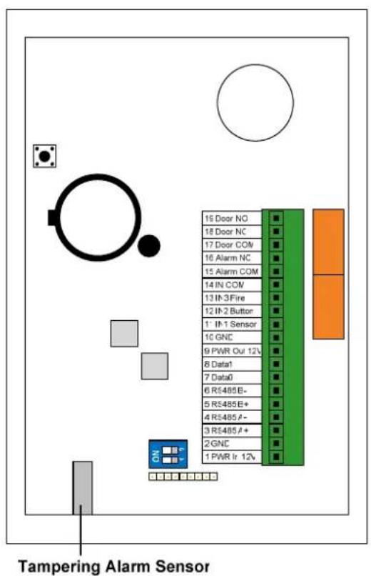
GV-AS100
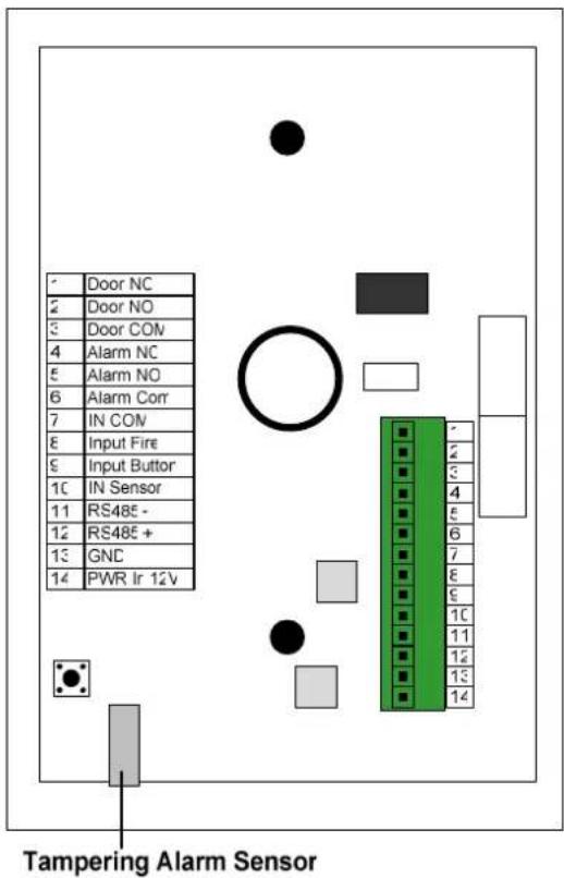
GV-AS1010
Figure 1-4
1.2 Installation
Open the GV-AS100 / 1010 to access the terminal block.
GV-AS100
| 19 Door NO | ■ |
| 18 Door NC | ■ |
| 17 Door COM | ■ |
| 16 Alarm NO | ■ |
| 15 Alarm COM | ■ |
| 14 IN COM | ■ |
| 13 IN3 Fire | ■ |
| 12 IN2 Button | ■ |
| 11 IN1 Sensor | ■ |
| 10 GND | ■ |
| 9 PWR Out 12V | ■ |
| 8 Data1 | ■ |
| 7 Data0 | ■ |
| 6 RS485 B- | ■ |
| 5 RS485 B+ | ■ |
| 4 RS485 A- | ■ |
| 3 RS485 A+ | ■ |
| 2 GND | ■ |
| 1 PWR In 12V | ■ |
| Pin | Function Pin Function | ||
| 1 | 12V Power 11 Sensor | IN1 | |
| 2 | GND 12 Button IN2 | ||
| 3 | RS-485 A+ for ASBox / ASNet or PC connection | 13 | Fire IN3 |
| 4 | RS-485 A-for ASBox / ASNet or PC connection | 14 | IN COM |
| 5 | RS-485 B+ for GV-Reader connection | 15 | Alarm COM |
| 6 | RS-485 B- for GV-Reader connection | 16 | Alarm NO |
| 7 Wiegand Data 0 17 Door COM | |||
| 8 Wiegand Data 1 18 Door NC | |||
| 9 12V Power Supply 19 Door NO | |||
| 10 GND | |||
Figure 1-5
GV-AS1010
| 1 | Door NC |
| 2 | Door NO |
| 3 | Door COM |
| 4 | Alarm NC |
| 5 | Alarm NC |
| 6 | Alarm Com |
| 7 | IN COM |
| 8 | Input Fire |
| 9 | Input Button |
| 10 | Input Sensor |
| 11 | RS485 - |
| 12 | RS485 + |
| 13 | GND |
| 14 | PWR In 12V |
| Pin | Function | Pin Function | ||
| 1 | Door NC | 8 | Input Fire | |
| 2 | Door NO 9 | Input Button | ||
| 3 | Door COM | 10 | Input Sensor | |
| 4 | Alarm NC | 11 | RS485 - | |
| 5 | Alarm NO | 12 | RS485 + | |
| 6 | Alarm Com | 13 | GND | |
| 7 | IN COM | 14 | PWR In 12V | |
Figure 1-6
1.2.1 Connecting Card Readers
1.2.1.A Wiegand Readers (GV-AS100 Only)
GV-AS100 provides one Wiegand input for connection of the Wiegand reader ranging from 26 to 64 bits. Through the GV-AS100 keypad, you can set the Wiegand reader as the entry or exit reader. To define the reader, see the AS100 Function option in 1.3.5 Setting Parameters.
Note: Wiegand connection is not supported for GV-AS1010.
The table below shows the pin assignments of the Wiegand input on GV-AS100. Please consult the documentation of your Wiegand reader for wiring.
| Pin | Function |
| 7 Wiegand Data 0 | |
| 8 Wiegand Data 1 | |
| 9 12V Power Supply | |
| 10 | GND |
1.2.1.B RS485 Readers
For long-distance connection and non-Wiegand card readers, you can establish RS-485 connection with any GV-Readers and GV-GF1911 / 1912. GV-AS100 can connect with 1 reader through RS-485 connection. GV-AS1010 can connect with up to 2 readers through a single RS-485 cable.
When connecting a second reader to GV-AS1010, you will need to set up a separate power source to power the second reader.
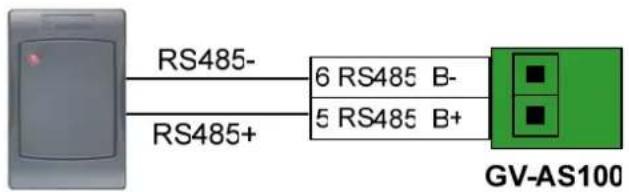
GV-Readers or GV-GF Fingerprint Readers
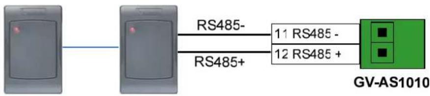
flowchart
graph LR
    A["Device 1"] -->|RS485-| B["11 RS485 -"]
    A -->|RS485+| C["12 RS485 +"]
    B --> D["GV-AS1010"]
    C --> D
Up to 2 GV-Readers and GV-GF Fingerprint Readers
Figure 1-7
1.2.1.C Network Readers (GV-AS1010 Only)
GV-AS1010 supports network connection with GV-CR420 and GV-GF1921 / 1922. Through the GV-AS1010 keypad, you can set the network reader as the entry or exit reader. To define the reader, see the Door/Gate Function option in 2.3.2 Programming the GV-AS110 / 1110.
Note:
- Network connection with readers is not supported for GV-AS110.
- GV-AS1010 does not support network connection with GV-GF1911 / 1912.
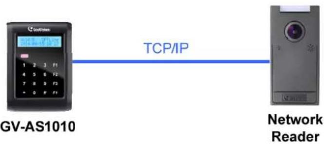
flowchart
graph LR
    A["GV-AS1010"] -->|TCP/IP| B["Network Reader"]
Figure 1-8
1.2.2 Connecting Input Devices
GV-AS100 / 1010 supports 3 types of inputs:
- Sensor inputs, e.g. door status sensor
- Button inputs, e.g. door opener
- Fire Sensor inputs, e.g. fire detector
All inputs are dry contact and can be configured as normally open (NO) or normally closed (NC) through the GV-AS100 / 1010 keypad. The default value is NO. To change the input status, see the Set Contact Type option in 1.3.5 Setting Parameters.
The table below shows the pin assignments of input connectors on GV-AS100 and GV-AS1010.
GV-AS100
| Pin | Function |
| 11 | Sensor IN1 |
| 12 | Button IN2 |
| 13 | Fire Sensor IN3 |
| 14 | IN COM |
GV-AS1010
| Pin | Function |
| 7 | IN COM |
| 8 | Input Fire |
| 9 | Input Button |
| 10 | Input Sensor |
1.2.3 Connecting Output Devices
GV-AS100 supports 2 types of outputs:
- Alarm outputs, e.g. siren or bell
- Door outputs, e.g. electronic lock
The table below shows the pin assignments of output connectors on GV-AS100 / 1010.
GV-AS100
| Pin | Function |
| 15 | Alarm COM |
| 16 | Alarm NO |
| 17 | Door COM |
| 18 | Door NC |
| 19 | Door NO |
GV-AS1010
| Pin Function | ||
| 1 | Door | NC |
| 2 | Door | NO |
| 3 | Door | COM |
| 4 | Alarm | NC |
| 5 | Alarm | NO |
| 6 | Alarm | Com |
Check if your output device meets the following absolute maximum ratings before connecting it to the Door outputs.
| Breakdown Voltage | 240V AC, 30V DC |
| Continuous Load Current | 5A (NO), 3A (NC) |
| Note: Absolute Maximum Ratings are those values beyond which damage to GV-AS100 circuit board may occur. Continuous operation of GV-AS100 at the absolute rating level may affect GV-AS100 reliability. | |
To connect an output device:
The example below illustrates the connection of a locking device to GV-AS100 / 1010.
Connect the (+) point on the locking device to the Door COM on GV-AS100 / 1010, connect the two (-) points of the locking device and the external power supply together, and connect the (+) point on the external power supply to the Door NO or Door NC on GV-AS100 / 1010 based on the state of the locking device.
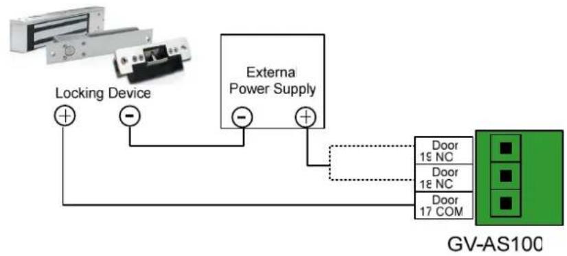
flowchart
graph TD
    A["Locking Device"] --> B["External Power Supply"]
    B --> C["GV-AS10C"]
    D["Door 15 NC"] --> C
    E["Door 18 NC"] --> C
    F["Door 17 COM"] --> C
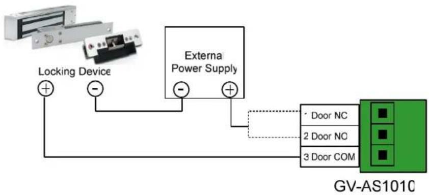
flowchart
graph TD
    A["Locking Device"] -->|+| B["External Power Supply"]
    A -->|-| B
    B --> C["GV-AS1010"]
    C --> D["Door NC"]
    C --> E["2 Door NO"]
    C --> F["3 Door COM"]
Figure 1-9
1.2.4 Connecting the PC
Connecting GV-AS110 / 1110 to a computer allows you to access its Web interface and connect it to GV-ASManager if the computer is installed with GV-ASManager. GV-ASManager software can monitor the access information and alarm messages from GV-AS100 / 1010. The communication link between the computer and GV-AS100 / 1010 is as below.
GV-AS100: RS-485 connection or network connection
- RS-485 connection: a RS-485 to RS-232 converter is required
• Network connection: an optional GV-ASBox or GV-ASNet is required
GV-AS1010: Network connection
IMPORTANT: To enable connection to PC on GV-AS100, Switch 1 must be turned on. See 1.2.4.C Switches.
1.2.4.A Connecting GV-AS100 to PC
RS-485 Connection between GV-AS100 and PC
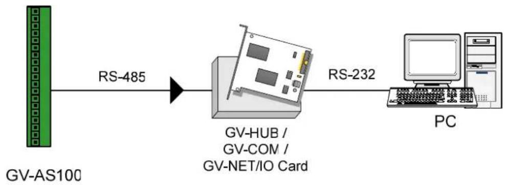
The figure below illustrates the RS-485 connection to the computer. For this connection, a RS-485 to RS-232 converter between GV-AS100 and the computer is required. You can use GV accessories, such as GV-Hub, GV-COM and GV-NET/IO Card, as the RS-485/RS-232 converter.
flowchart
graph LR
    A["GV-AS100"] -->|RS-485| B["GV-HUB / GV-COM / GV-NET/IO Card"]
    B -->|RS-232| C["PC"]
Figure 1-10
The table shows the pin assignments of related RS-485 connectors on GV-AS100.
| Pin | Function | |
| 3 | RS-485 | A+ |
| 4 | RS-485 | A- |
Note: When connecting multiple GV-AS100 through RS-485 connection, you can use the keypad on GV-AS100 to program every unit's ID. See 1.3.5 Setting Parameters.
Network Connection between GV-AS100 and PC
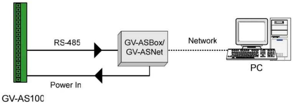
The figure below illustrates the network connection to the computer. For this connection, the optional product GV-ASBox or GV-ASNet is required.
flowchart
graph LR
    A["GV-AS100"] -->|RS-485| B["GV-ASBox/GV-ASNet"]
    A -->|Power In| B
    B -->|Network| C["PC"]
Figure 1-11
Connect two power wires and two RS-485 wires from GV-ASBox / GV-ASNet to GV-AS100. The table below shows the pin assignments of related connectors on GV-AS100.
| Pin | Function | Pin | Function | |
| 1 | Power In | 12V | 3 RS-485 A+ | |
| 2 | GND | 4 | RS-485 | A- |
Also see 9.1.4.A Connecting GV-AS100 / 110 / 120.
1.2.4.B Connecting GV-AS1010 to PC
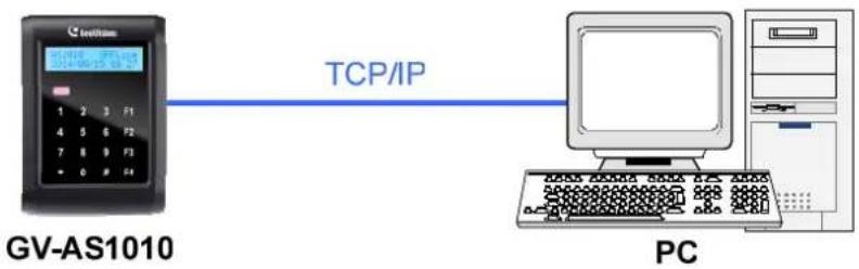
The figure below illustrates the network connection between GV-AS1010 and the computer.
flowchart
graph LR
    A["GV-AS1010"] -->|TCP/IP| B["PC"]
Figure 1-12
Note: GV-AS1010 is only compatible with GV-ASManager V4.2.3 or later.
1.2.4.C Switches (GV-AS100 Only)
Switch 1: When Switch 1 is ON, GV-AS100 can connect to GV-ASManager, GV-ASBox or GV-ASNet. When Switch 1 is OFF, the connection is unavailable. By default Switch 1 is set to ON.
Switch 2: When the RS-485 connection between GV-AS100 and computer is longer than 600 meters (1968.50 feet), the RS-485 signal may become weak. In this case, turn Switch 2 ON to have a 120-Ohm resistor.
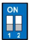
Figure 1-13
1.2.5 Connecting the Power
The supplied power adaptor can be connected to any power source supplying from 100 to 240V. Using the supplied power cord and adaptor, connect GV-AS100 / 1010 to the power.
Note: Power should only be applied to the unit when all connections are completed and tested.
1.2.6 Fitting the Battery
GV-AS100 / 1010 includes a battery, providing power to GV-AS100 / 1010 settings and real-time clock circuitry. When the power in the battery becomes low, the message “Low Battery” will appear on GV-AS100 / 1010 LCD. In this case, replace the battery. All settings on GV-AS100 / 1010 will disappear about 10 hours after the battery stops working, and GV-AS100 / 1010 will be restored to default settings.
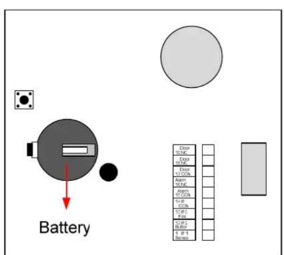
GV-AS100
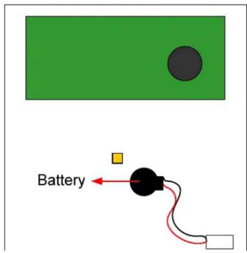
GV-AS1010
Figure 1-14
Note:
- Make sure the plastic insulation film under the battery is removed.
- It is recommended to replace the battery annually. GV-AS100 uses a 3V lithium battery that can be purchased on your own. For GV-AS1010, contact your sales representative to acquire replacement batteries designated for GV-AS1010.
1.2.7 Using the Function Keys (GV-AS1010 Only)
GV-AS1010 comes with four function keys for time and attendance records. On the Web interface of GV-AS1010, you can define function keys. Refer to the Function Key section in Chapter 8.
Before employees present their access card to GV-AS1010, they can press the function keys to indicate the card swipe is the start or end of Work Time, Away, Overtime or Break Time. You can look up the attendance data in GV-TAWeb. Refer to the GV-TAWeb for Workforce Schedule and Payroll chapter in GV-ASManager User's Manual for details.
On the Web interface of GV-AS1010, you can specify whether or not the door or elevator call button will unlock when an access card is presented after a function key is pressed. Refer to the Function Key Configuration section in Chapter 8 to see the related settings.
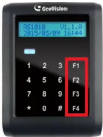
Figure 1-15
Note: When using GV-AS1010 firmware V1.0, presenting the access card after pressing a function key will not unlock the door or elevator call button. The user will need to present the access card again to gain access.
1.3 Programming Mode
After powering on GV-AS100, you must create a Master Card first. It is required to present the Master Card and enter its PIN code every time before programming GV-AS100.
For GV-AS1010, you must create two cards first, an Enroll Card and a Delete Card. The Enroll Card is used for adding new cards and the Delete Card is used for deleting cards. Either card will allow you to program the various configurations on GV-AS1010.
Note: Cards complying with ISO 14443A standard for smart card technology can be formatted as Master Card, Enroll Card or Delete Card. Only one Master Card can be created.
To create a Master Card for GV-AS100:
- Power on the unit. The LCD displays Enter Master Card.
- Present a card to be the Master Card. The LCD displays Master PIN Code: 1234.
- Keep the default PIN code as 1234, and press #. The LCD displays Succeed.
Alternatively, you can press any four digits on the keypad to change the default value. The double confirmation of the new PIN code is required. After this, the LCD should display the message of success.
After the Master Card is created, GV-AS100 will run a self test and display the message "Master Memory Test". After it is finished, you can see the message of GV-AS100 online or offline followed by a date and time. Then you can start programming GV-AS100.
To create a Enroll Card and a Delete Card for GV-AS1010:
- Power on the unit. The LED flashes blue.
- Present a card to be the Enroll Card.
- Present a card to be the Delete Card.
After 1 to 2 minutes, the LED should be a constant blue light to indicate READY.
The table below shows the codes to start various programming and display system information.
| Code Function | |
| *227 (*CAR) | Accesses the Card Manager function. |
| *276 (*ARM) | Accesses Security Mode. |
| *347 (*DIS) | Displays system information. |
| *738 (*SET) | Accesses parameter settings. |
| *737 (*RES) | Restores GV-AS100 / 1010 to factory defaults. |
| *837 (*TES) | Tests numeral keys to see if they can be displayed properly. |
Before programming GV-AS100 / 1010, you also need to know the following keys.
| Key Function | |
| * Used to cancel the selection, or go back to the previous page. | |
| # Used to save the data that was modified or programmed in the system and quit. | |
| 0 Used to go to the next page. | |
1.3.1 Quick Reference of Programming Table
GV-AS100
| Card Manger | ||||
| Add | New Card 1) N, 2) A, 3) B, 4) S | |||
| Del | Card Data | |||
| Reset Card's APB | ||||
| Display System | ||||
| Door's Auth Mode | ||||
| Door's Event | ||||
| ASBox Comm. State | ||||
| Memory's State | ||||
| ID & IP Address | ||||
| Display Version | ||||
| Set Parameter | ||||
| Set Local Time | ||||
| Set AS100 ID | ||||
| Set Auth. Mode | ||||
| Auth. | Schedule | |||
| Fixed Card Mode | ||||
| Fixed Card + PIN | ||||
| Fixed Card Common | ||||
| Local Unlock Mode | ||||
| Local Lock Mode | ||||
| AS100 Function | ||||
| GV-ASBox | ||||
| Control Type Door Entry Type Anti-Passback | ||||
| Door Exit Type | Anti-Passback | |||
| Parking Entry Type | Anti-Passback | |||
| Parking Exit Type | Anti-Passback | |||
| Elevator Control | ||||
| Master PIN Change | ||||
| Local Rest Time | ||||
| Set Held Open Time | ||||
| Set Alarm Event | ||||
| Held Open Alarm | ||||
| Force | Open Alarm | |||
| Fire Alarm | ||||
| Tamper Alarm | ||||
| Access | Denied | |||
| Set Fire Action | ||||
| Unlock | Door/Gate | |||
| Lock | Door/Gate | |||
| Unchanged | ||||
| Set Contact | Type | |||
| Door/Car | Sensor | |||
| Door/Gate | Button | |||
| Fire | Sensor | |||
GV-AS1010
| Card Manger | |||
| Reset Card's APB | |||
| Display System | |||
| Door's Auth Mode | |||
| Door's Event | |||
| Memory's State | |||
| ID & IP Address | |||
| Display Version | |||
| Set Parameter | |||
| Set Local Time | |||
| Set AS1010 ID | |||
| Set AS1010 IP | |||
| Set Auth. Mode | |||
| Auth. Schedule | |||
| Fixed Card Mode | |||
| Fixed Card + PIN | |||
| Fixed Card Common | |||
| Local Unlock Mode | |||
| Local Lock Mode | |||
| AS1010 Function | |||
| Door Entry Type | Anti-Passback | ||
| Door Exit Type | Anti-Passback | ||
| Parking Entry Type | Anti-Passback | ||
| Parking Exit Type | Anti-Passback | ||
| Elevator Control | |||
| Enroll Pin Change | |||
| Delete Pin Change | |||
| Local Rest Time | |||
| Set Held Open Time | |||
| Set Alarm Event | |||
| Held Open Alarm | |||
| Force Open Alarm | |||
| Fire Alarm | |||
| Tamper Alarm | |||
| Access Denied | |||
| Tailgating Alarm | |||
| Set Fire Action | |||
| Unlock Door/Gate | |||
| Lock Door/Gate | |||
| Unchanged | |||
| Set Contact Type | |||
| Door/Car Sensor | |||
| Door/Gate Button | |||
| Fire Sensor | |||
| Set Function Key | |||
| Set F1 | Work Time (Start), Work Time (End), Away (Start), Away (End), Overtime (Start), Overtime (End), Break Time(Start), Break Time (End) | ||
| Set F2 | |||
| Set F3 | |||
| Set F4 | |||
Note: Tailgating alarm function is currently not functional.
1.3.2 Adding and Deleting a Card
Note:
- GV-ASManager cannot manage the cards enrolled on GV-AS100 / 1010, since the card data will not be transmitted to GV-ASManager.
- The cards added through GV-ASManager cannot be deleted on GV-AS100 / 1010.
1.3.2.A Adding a Card
Up to 1,000 cards can be enrolled on GV-AS100 / 1010 directly without additional software. When working with GV-ASManager, GV-AS100 / 1010 can support up to 40,000 cards.
GV-AS100
- Press the code *227 (*CAR).
- Present the Master Card and enter its PIN code. The LCD displays Add New Card.
- Press #. The LCD displays Enter New Card.
- To add a card, you can either press the card number or present the card to the unit. The LCD displays the card number and these options: 1)N 2)A 3)B 4)S.
N stands for a normal card; A stands for a two-person A card; B stands for a two-person B card; S stands for a security card. - Select a card type, and enter and confirm a PIN code for the new card.
The LCD displays Store New Card, 1. Yes? 2. No?. - Press 1 to save and exit.
GV-AS1010
- Present the Enroll Card and enter its PIN code. The LCD displays Enter New Card.
- To add a card, you can either press the card number or present the card to the unit. The LCD displays the card number and these options: 1)N 2)A 3)B 4)S.
N stands for a normal card; A stands for a two-person A card; B stands for a two-person B card; S stands for a security card. - Select a card type, and enter and confirm a PIN code for the new card.
The LCD displays Store New Card, 1. Yes? 2. No?. - Press 1 to save and exit.
1.3.2.B Deleting a Card
GV-AS100
- Press the code *227 (*CAR).
- Present the Master Card and enter its PIN code. The LCD displays Add New Card.
- Press 0. The LCD displays Del Card Data.
- Press #. The LCD displays Enter Del Card.
- You can either press the card number or present the card to the unit.
The LCD displays: Delete, 1. Yes? 2. No?.
- Press 1 to save and exit.
GV-AS1010
- Present the Delete Card and enter its PIN code. The LCD displays Enter Del Card.
- You can either press the card number or present the card to the unit.
The LCD displays: Delete, 1. Yes? 2. No?
- Press 1 to save and exit.
1.3.3 Resetting the APB Function
You can reset the anti-passback (APB) function of a card to allow a user to re-access the entry or exit reader.
- Press the code *227 (*CAR).
- Present the Master Card or Enroll/Delete Card, and enter its PIN code. The LCD displays Add New Card.
- Press 0 several times. The LCD displays Reset Card's APB.
- Press #. The LCD displays Enter Card.
- You can either press the card number or present the card to the unit.
The LCD displays: Reset, 1. Yes? 2. No?.
- Press 1 to save and exit.
1.3.4 Accessing the Security Mode
The security mode is used to arm GV-AS100 / 1010. In the arm mode, no cards can be granted access and no one can program the unit. Only the security card that is associated with a PIN code can be used to disarm the unit.
1.3.4.A Enabling the Security Mode
Before you can access the security mode, you need to create a security card first.
- To create a security card, follow the steps 1 to 4 in 1.3.2.A Adding a Card, select 4)S as card type and create a PIN code for the security card.
- To access security mode, press the code *276 (*ARM).
The LCD displays Start Arm? Enter PIN Code. - Press the PIN code of the security card.
The LCD displays Start Arm? Enter Security Card. - Present the security card. The security mode is enabled.
1.3.4.B Disabling the Security Mode
To disable the security mode, press any key, enter the PIN code of the security card and present the security card.
1.3.5 Setting Parameters
You can define the parameters of some features on GV-AS100 / 1010.
IMPORTANT: Once connecting to GV-AS100 / 1010, GV-ASManager will load its parameters to GV-AS100 / 1010. That means some of the parameters you set up here may be overwritten by GV-ASManager later.
- Press the code *738 (*SET).
- Present the Master Card and enter its PIN code. The LCD displays Set Local Time.
- Press 0 to change the options. Press # to select the option for further programming.
| Option Function | |
| Set Local Time Sets the time, time zone and enables daylight saving. | |
| Set AS100 / 1010 ID | Sets the ID of GV-A100 / 1010 from 1 to 255. |
| Set AS1010 IP Sets the IP of GV-AS1010. (GV-AS1010 only) | |
| Set Auth. Mode Sets an authentication mode for the door/gate.■Auth. Schedule: Follows the authentication schedule set on GV-ASManager.■Fixed Card Mode: Grants access after the card is presented. Ignores the authentication schedule of GV-ASManager.■Fixed Card + PIN: Grants access after the user presents the card and then enters the card's PIN code. Ignores the authentication schedule of GV-ASManager.■Fixed Card/Common: Grants access after the user presents the card or enters the door's password. Enter the door's password after the LCD displaysCommon Password. Ignores the authentication schedule of GV-ASManager.■Local Unlock Mode: Remains open. The held-open state cannot be cleared through GV-ASManager.■Local Lock Mode: Remains locked. The locked state cannot be cleared through GV-ASManager. | |
| AS100 / 1010 Function | ■ GV-ASBox: Enables or disables the connection to GV-ASBox / GV-ASNet. (GV-AS100 only)■ Control Type:⊙ Door Entry Type: Sets GV-AS100 / 1010 as entry reader of a door.⊙ Door Exit Type: Sets GV-AS100 / 1010 as exit reader of a door.⊙ Parking Entry Type: Sets GV-AS100 / 1010 as entry reader of a parking gate.⊙ Parking Exit Type: Sets GV-AS100 / 1010 as exit reader of a parking gate.⊙ Elevator Type: GV-AS100 / 1010 reader is installed in the elevator for access control.■ Anti-Passback: Enables or disables the Anti-Passback function. |
| Master PIN Change | Changes the PIN code of the Master Card. (GV-AS100 only) |
| Enroll Pin Change | Changes the PIN code of the Enroll Card. (GV-AS1010 only) |
| Delete Pin Change | Changes the PIN code of the Delete Card. (GV-AS1010 only) |
| Local Rest Time Sets | the time (1 to 255 sec.) that a door/gate remains open after which the door will automatically be locked. |
| Set Held Open Time | Sets the time (5 to 9999 sec.) that a door/gate can be held open before an alarm is generated. |
| Set Alarm Event Enables or disables the alarm settings. | |
| Set Fire Action Locks | or unlocks the door/gate, or remains the current state when a fire condition occurs. |
| Set Contact Type Sets | the inputs to be normally open (NO) or normally closed (NC). |
| Set Function Key Define | the function keys to indicate the start time or end time of the attendance activities below (GV-AS1010 only): Work Time, Away, Overtime, Break Time. |
Note: The Parking Entry Type and Parking Exit Type only work when the sensor input of Car Detection is activated. When the card is present but the sensor inputs are not activated, the message "No Car In Zone" will appear in the GV-AS100 / 1010's LCD.
1.3.6 Displaying System Information
To display system information, press the code *347 (*DIS).
| Option Function | |
| Door's Auth. Mode Displays the authentication mode of the door. | |
| Door's Event Displays what kind of event happened at the door. | |
| ASBox Comm. State (GV-AS100 only) | Displays the connection status with GV-ASBox / GV-ASNet.■User Disenable: The connection to GV-ASBox / GV-ASNet is not enabled.■Comm. Fail: The connection to GV-ASBox / GV-ASNet failed.■Comm. Normal: The connection to GV-ASBox / GV-ASNet succeeded. |
| Memory's State Displays the memory usage of GV-AS100 / 1010.■Capacity: Displays the total number of events that can be recorded on GV-AS100 / 1010. The maximum number is 65536. GV-AS100 / 1010 will overwrite the oldest events when the limit is reached. When GV-AS100 / 1010 is connected to GV-ASManager, the event data will be uploaded to the server and the buffer of GV-AS100 / 1010 will be cleared.■Stored: Displays the number of events that has been recorded. | |
| ID & IP Address Displays the ID and IP address of GV-AS100 / 1010. | |
| Display Version Displays the firmware version of GV-AS100 / 1010. | |
1.3.7 Restoring Factory Defaults
The restore function is used to clear all configured options and cards from GV-AS100 / 1010 memory and bring back the unit to factory defaults.
IMPORTANT: Restoring default settings will delete all cards enrolled on GV-AS100 / 1010.
- Press the code *737 (*RES).
- Present the Master Card or Enroll / Delete Card and enter PIN Code.
The LCD displays Default Setting 1. Yes? 2. No?. - Press 1. The LCD displays Default Setting Memory Test...
- When the unit returns to factory defaults, the LCD displays Enter Master Card.
1.4 Web-Based Configurations
GV-AS100
Through GV-ASBox or GV-ASNet, GV-AS100 can communicate with GV-ASManager over the network. Using GV-ASBox or GV-ASNet, you can also access the Web interface of GV-AS100.
Refer to Chapter 9 Optional Devices to see how to connect a GV-ASBox or GV-ASNet and how to access the Web interface of GV-AS100.
GV-AS1010
GV-AS1010 can communicate with GV-ASManager over the network. The network interface also allows you to access the Web interface of GV-AS1010.
Refer to Chapter 7 Installing on a Network for detailed instructions on setting a fixed or dynamic IP address to access GV-AS1010.
Refer to Chapter 8 The Web Interface for details on the setup pages of the Web interface. Through the Web interface, you can configure general settings, input/output devices, associated doors/gates and connected readers.
1.5 GV-AS100 / 1010 Specifications
GV-AS100
| CPU 8-bit RISC microprocessor | ||
| Number of User Cards | 1,000 / 40,000 cards (standalone / networked or RS-485 mode) | |
| Frequency | 13.56 MHz for ISO14443A (Mifare DESFire, Mifare Plus and Mifare Classic) | |
| Event Buffer 65,536 events and log data | ||
| Power 100 ~ 240V AC, 50 ~ 60 Hz | ||
| Wiegand Interface | 1 Wiegand interface, 26 ~ 64 bit format | |
| 12V DC Power Supply, 200mA | ||
| RS-485 Interface | 1 RS-485 interface only for 1 GV-Reader or GV-GF Fingerprint Reader | |
| Communication Protocol RS-485 | ||
| Digital I/O | Input 3 inputs, dry contact, NO / NC | |
| Output 2 outputs | ||
| Supported ID Format Built-in reader reads UID only | ||
| Operating Temperature 0 ~ 65°C / 32 ~ 149°F | ||
| Operating Humidity 10% ~ 90% RH (non-condensing) | ||
| Dimensions (W X H X D) 96 x 137 x 27 mm / 3.78 x 5.39 x 1.06 in | ||
| Weight 250 g / 0.55 lb | ||
| Ingress Protection IP54 | ||
| Certification CE, FCC, RoHS | ||
GV-AS1010
| CPU | 32-bit ARM7TDMI | |
| Number of User Cards 1,000 / | 40,000 cards (standalone / networked mode) | |
| Frequency | 13.56 MHz for ISO14443A (Mifare DESFire, Mifare Plus and Mifare Classic) | |
| Event Buffer 65,536 events and log data | ||
| Power 100 ~ 240V AC, 50 ~ 60 Hz | ||
| RS-485 Interface | 1 RS-485 interface for GV-Readers and GV-GF Fingerprint Readers (max. 2 readers) | |
| TCP/IP Interface 1 TCP/IP interface for GV-CR420 and GV-GF1921 / 1922 | ||
| Communication Protocol TCP/IP | ||
| Digital I/O | Input 3 inputs, dry contact, NO / NC | |
| Output 2 relay outputs (30V DC, 5A; 110V AC ~ 250V AC, 5A ) | ||
| Supported ID Formats Built-in reader reads both GID and UID | ||
| Operating Temperature 0 ~ 65°C / 32 ~ 149°F | ||
| Operating Humidity 10% ~ 90% RH (non-condensing) | ||
| Dimensions (W X H X D) 96 x 137 x 27 mm / 3.78 x 5.39 x 1.06 in | ||
| Weight 250 g / 0.55 lb | ||
| Ingress Protection IP54 | ||
| Certification | CE, FCC, RoHS | |
All specifications are subject to change without notice.
- GV-AS110 / 1110 Controller
2.1 Introduction
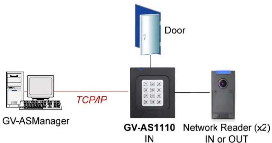
GV-AS110 / 1110 is a single door controller with a built-in reader. You can connect one more card reader to GV-AS110 and up to two more card readers to GV-AS1110 for entry and exit applications. GV-AS110 comes with built-in RS-485 and Wiegand interface, while GV-AS1110 comes with TCP/IP network port.
GV-AS110 / 1110 has the capability to store up to one thousand cards under standalone mode and up to 40,000 cards when connected to GV-ASManager. Programming of GV-AS110 / 1110 can be done either on the keypad or from the software GV-ASManager.
An economic solution for access control, GV-AS110 / 1110 is suitable for controlling doors, parking gates and access to elevator call buttons.
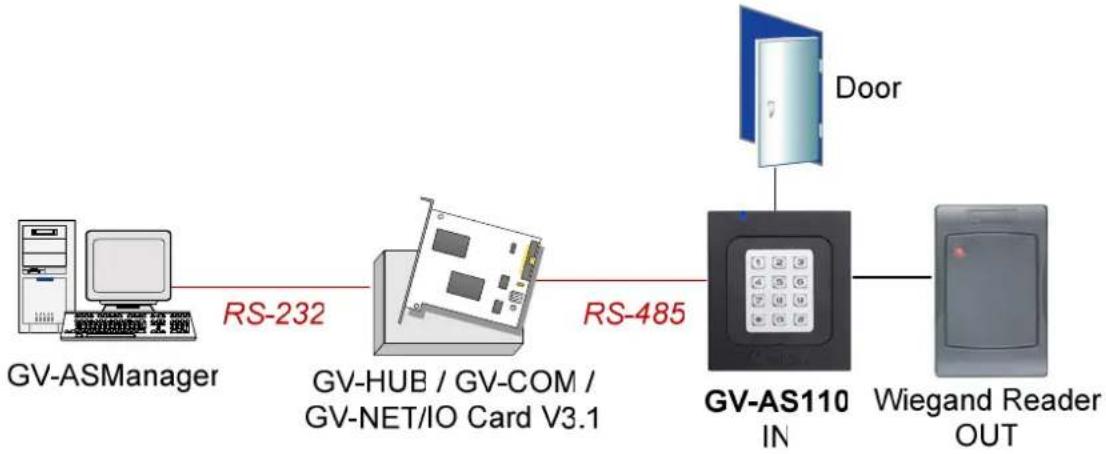
flowchart
graph LR
    A["GV-ASManager"] -->|RS-232| B["GV-HUB / GV-COM / GV-NET/IO Card V3.1"]
    B -->|RS-485| C["GV-AS110 IN"]
    C --> D["Wiegand Reader OUT"]
    C --> E["Door"]
flowchart
graph LR
    A["GV-ASManager"] -->|TCP/IP| B["GV-AS1110 IN"]
    B --> C["Network Reader (x2) IN or OUT"]
    D["Door"] --> B
Figure 2-1
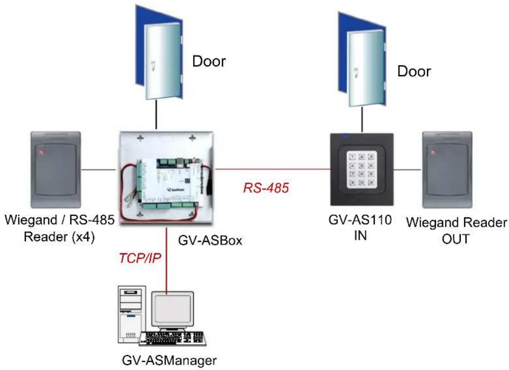
GV-AS110 can make network connection to GV-ASManager using the optional GV-ASBox or GV-ASNet. With GV-ASBox, two-door control is also possible as illustrated below.
flowchart
graph TD
    A["Wiegand / RS-485 Reader (x4)"] --> B["GV-ASBox"]
    B -->|TCP/IP| C["GV-ASManager"]
    D["Door"] --> B
    E["Door"] --> F["GV-AS110 IN"]
    F --> G["Wiegand Reader OUT"]
    style B fill:#f9f,stroke:#333
    style F fill:#ccf,stroke:#333
Figure 2-2 Through GV-ASBox
flowchart
graph LR
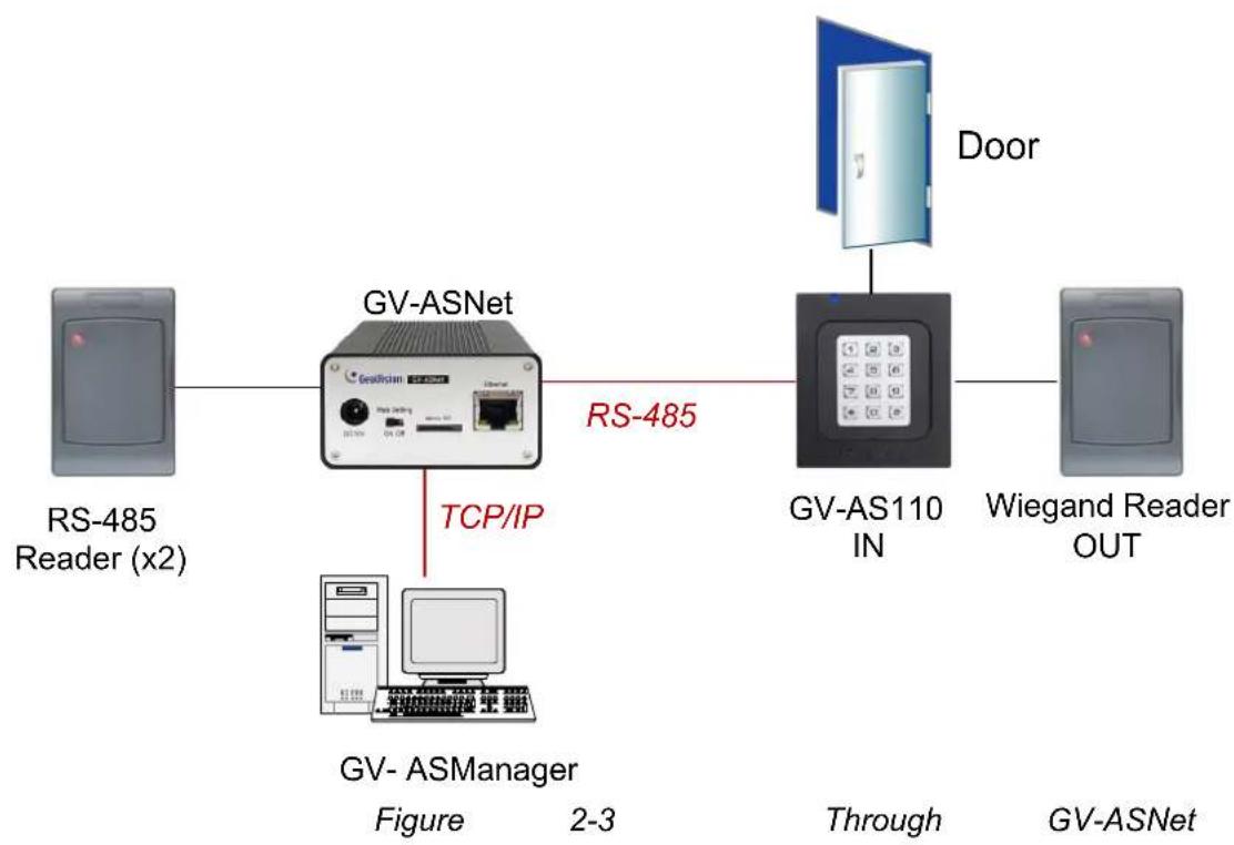
    A["RS-485 Reader (x2)"] --> B["GV-ASNet"]
    B -->|TCP/IP| C["GV-ASManager"]
    C --> D["GV-AS110 IN"]
    D --> E["Door"]
    E --> F["Wiegand Reader OUT"]
    style B fill:#f9f,stroke:#333
    style D fill:#ccf,stroke:#333
    style F fill:#cfc,stroke:#333
2.1.1 Main Features
GV-AS110
- 1 door (one-way and two-way control), expandable to 2 doors with optional GV-ASBox
• 1,000 / 40,000 cards (standalone / networked or RS-485 mode) - Easy programming from keypad
• Built-in 3 digital inputs and 2 relay outputs - 1 Wiegand output (26 \~ 64 bits) for extra reader programming
• Built-in 13.56 MHz Reader
• Built-in tampering alarm sensor
• IP54-compliant housing
• Anti-Passback (APB) support
GV-AS1110
• 1 door (one-way and two-way control)
• 1,000 / 40,000 cards (standalone / networked mode)
- Easy programming from keypad
• Built-in 2 digital inputs and 1 relay outputs
• 1 network interface for connection with GV-ASManager and TCP/IP reader
• Built-in 13.56 MHz Reader
• Built-in tampering alarm sensor
- Weather-proof and IP66-compliant housing (for outdoor use)
• Anti-Passback (APB) support
2.1.2 Packing List
GV-AS110
GV-AS110
• Power Adaptor 12V DC / 1.25A
- Power Cord
- Screw x 2
- Screw Anchor x 2
- Front Cover Plate x 2
- Enroll Card
- Delete Card
• GV-AS ID F Card x 20
- Software CD
GV-AS1110
GV-AS1110
• Power Adaptor 12V DC / 1.25A
- Screw x 2
- Screw Anchor x 2
- Front Cover Plate x 2
- Enroll Card
- Delete Card
• GV-AS ID F Card x 20
- Torx Wrench
- Software CD
2.2 Installation
The wire assignment of the GV-AS110 cable data are illustrated below.
Front View
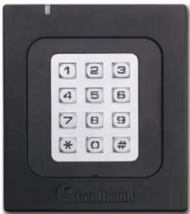
Figure 2-4
Rear View
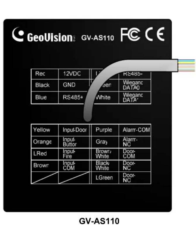
Figure 2-5
| Wire color Definition | |
| Red | 12V DC |
| Black | GND |
| Green Wiegand Data 0 | |
| White Wiegand Date 1 | |
| Blue | RS485+ |
| Light Blue RS485- | |
| Yellow Door Sensor IN1 | |
| Orange | Button IN2 |
| LRed Fire Sensor IN3 | |
| Brown IN COM (GND) | |
| Purple | Alarm COM |
| Gray | Alarm NO |
| Brown White Door COM | |
| Black White Door NC | |
| Light Green Door NO | |
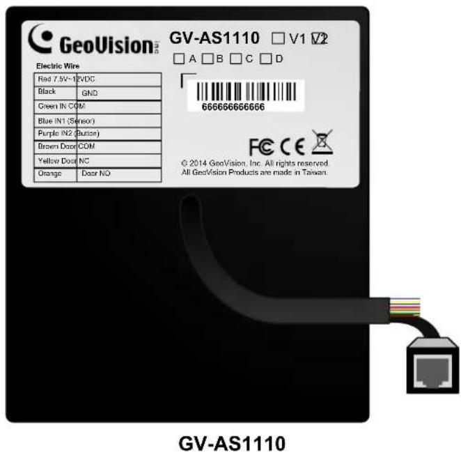
| Wire color Definition | ||
| Red | 7.5V~12V | DC |
| Black | GND | |
| Green | IN | COM |
| Blue | IN1 | (Sensor) |
| Purple | IN2 | (Button) |
| Brown | Door | Com |
| Yellow | Door | NC |
| Orange | Door | NO |
Figure 2-6
2.2.1 Connecting Card Readers
2.2.1.A Wiegand Readers (GV-AS110 Only)
GV-AS110 provides one Wiegand input for connection to the Wiegand reader ranging from 26 to 64 bits. Through the GV-AS110 keypad, you can set the Wiegand reader as the entry or exit reader. To define the reader, see the Door/Gate Function option in 2.3.2
Programming the GV-AS110 / 1110.
Note: Wiegand connection is not supported for GV-AS1110.
The table below shows the wire assignments of the Wiegand input on GV-AS110. Please consult the documentation of your Wiegand reader for wiring. You will need to set up a separate power source to power the Wiegand reader.
| Wire color Definition |
| Green Wiegand Data 0 |
| White Wiegand Date 1 |
2.2.1.B Network Readers (GV-AS1110 Only)
GV-AS1110 supports network port for network connection with GV-CR420 and GV-GF1921 / 1922. Through the GV-AS1110 keypad, you can set the network reader as the entry or exit reader. To define the reader, see the Door/Gate Function option in 2.3.2 Programming the GV-AS110 / 1110.
Note:
- Network connection with reader is not supported for GV-AS110.
- GV-AS1110 does not support network connection with GV-GF1911 / 1912.
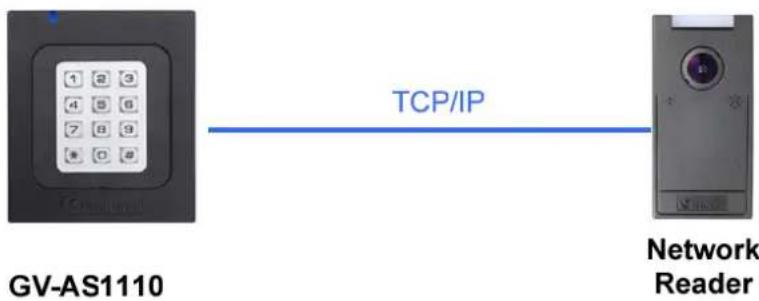
Figure 2-7
2.2.2 Connecting Input Devices
GV-AS110 supports 3 types of inputs, while GV-AS1110 supports 2 types of inputs.
- GV-AS110 / 1110: Sensor inputs, e.g. door status sensor
- GV-AS110 / 1110: Button inputs, e.g. door opener
- GV-AS110 only: Fire Sensor inputs, e.g. fire detector
All inputs are dry contact and can be configured as normally open (NO) or normally closed (NC) through the keypad. The default value is NO. To change the input status, see the Select Input Contact Type option in 2.3.2 Programming the GV-AS110 / 1110.
The tables below show the wire assignments of input connectors on GV-AS110 and GV-AS1110.
GV-AS110
| Wire color Definition | |
| Yellow Door Sensor IN1 | |
| Orange Button IN2 | |
| LRed Fire Sensor IN3 | |
| Brown IN COM (GND) |
GV-AS1110
| Wire color Definition | |
| Green IN COM (GND) | |
| Blue Door Sensor IN1 | |
| Purple | Button IN2 |
2.2.3 Connecting Output Devices
GV-AS110 supports 2 types of outputs, while GV-AS1110 supports 1 type of output:
- GV-AS110 only: Alarm outputs, e.g. siren or bell
- GV-AS110 / 1110: Door outputs, e.g. electronic lock
The table below shows the wire assignments of output connectors on GV-AS110 and GV-AS1110.
GV-AS110
| Wire color Definition | ||
| Purple | Alarm | COM |
| Gray | Alarm | NO |
| Brown & White Door COM | ||
| Black & White Door NC | ||
| Light green Door NO | ||
GV-AS1110
| Wire color Definition |
| Brown Door A Com |
| Yellow Door A NC |
| Orange Door A NO |
Check if your output device meets the following absolute maximum ratings before connecting it to the Door outputs.
| Breakdown Voltage | 250V AC, 220V DC |
| Continuous Load Current | 1A (30V DC), 0.3A (125V AC) |
| Note: Absolute Maximum Ratings are those values beyond which damage to GV-AS110 / 1110 circuit board may occur. Continuous operation of GV-AS110 at the absolute rating level may affect GV-AS110 / 1110's reliability. | |
To connect an output device:
The example below illustrates the connection of a locking device to GV-AS110 / 1110.
Connect the (+) point on the locking device to the Door COM wire on GV-AS110 / 1110, connect the two (-) points of the locking device and the external power supply together, and connect the (+) point on the external power supply to the Door NO or Door NC wire on GV-AS110 / 1110 based on the state of the locking device.
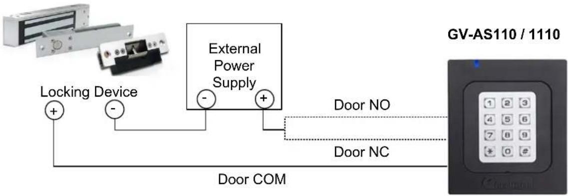
flowchart
graph LR
    A["Locking Device"] -->|+| B["External Power Supply"]
    C["Door COM"] -->|-| B
    B -->|+| D["Door NO"]
    B -->|-| E["Door NC"]
    D --> F["GV-AS110 / 1110"]
Figure 2-8
2.2.4 Connecting to the PC
Connecting GV-AS110 / 1110 to a computer allows you to access its Web interface and connect it to GV-ASManager if the computer is installed with GV-ASManager. The computer running GV-ASManager software can be used to monitor the access information and alarm messages from the controller. The communication link between the computer and GV-AS110 / 1110 is as below:
GV-AS110: RS-485 connection or network connection
• RS-485 connection: a RS-485 to RS-232 converter is required
• Network connection: an optional GV-ASBox or GV-ASNet is required
GV-AS1110: Network connection
2.2.4.A Connecting GV-AS110 to PC
RS-485 Connection between GV-AS110 and PC
The figure below illustrates the RS-485 connection between GV-AS110 and the computer. For this connection, a RS-485 to RS-232 converter between GV-AS110 and the computer is required. You can use GV accessories, such as GV-Hub, GV-COM and GV-NET/IO Card, as the RS-485/RS-232 converter.
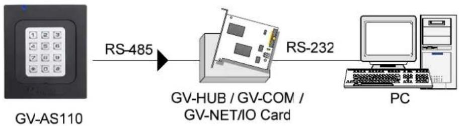
flowchart
graph LR
    A["GV-AS110"] -->|RS-485| B["GV-HUB / GV-COM / GV-NET/IO Card"]
    B -->|RS-232| C["PC"]
Figure 2-9
The table shows the wire assignments of RS-485 connection on GV-AS110.
| Wire color Definition | |
| Blue | RS485+ |
| Light Blue RS485- | |
Note: When connecting multiple GV-AS110 through RS-485 connection, you can use the keypad on GV-AS110 to program every unit's ID. See 2.3.2 Programming the GV-AS110 / 1110.
Network Connection between GV-AS110 and PC
The figure below illustrates the network connection between GV-AS110 and the computer. For this connection, a GV-ASBox or GV-ASNet is required.
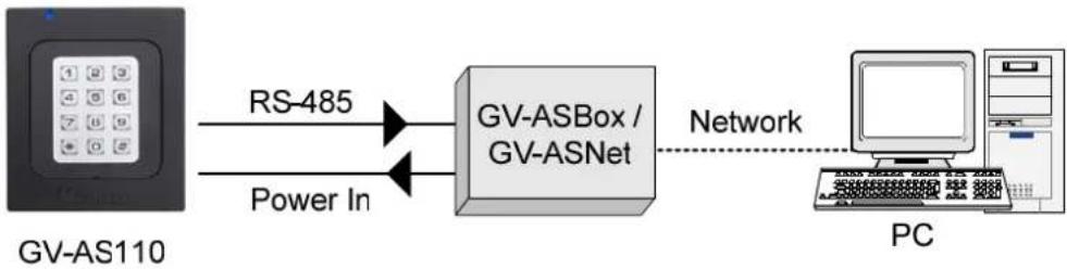
flowchart
graph LR
    A["GV-AS110"] -->|RS-485| B["GV-ASBox / GV-ASNet"]
    A -->|Power In| B
    B -->|Network| C["PC"]
Figure 2-10
Connect two power wires and two RS-485 wires from GV-AS110 to GV-ASBox / GV-ASNet. The table below shows the wire assignments of RS-485 connection on GV-AS110.
| Wire color Definition | |
| Red | 12V |
| Black | GND |
| Blue | RS485 + |
| Light Blue RS485 - | |
See 9.1.4.A Connecting GV-AS100 / 110 / 120 or 9.2.4.A Connecting GV-AS100 / 110 / 120 to see how to connect to GV-ASBox or GV-ASNet.
2.2.4.B Connecting GV-AS1110 to PC
The figure below illustrates the network connection between GV-AS1110 and the computer.
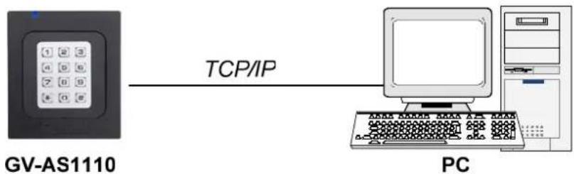
flowchart
graph LR
    A["GV-AS1110"] -->|TCP/IP| B["PC"]
Figure 2-11
Note: GV-AS1110 is only compatible with GV-ASManager V4.2.3 or later.
2.2.5 Connecting the Power
The supplied AC adaptor can be connected to any power source supplying from 100 to 240V. Connect 12V and GND wires to the supplied power adapter and then connect the power adapter to a power source. The table below shows the pin assignments of the power connectors on GV-AS110 and GV-AS1110.
| Wire color GV-AS110 Definition GV-AS1110 Definition | ||
| Red 12V DC 7.5V ~12V DC | ||
| Black | GND | GND |
Note: Power should only be applied to the unit when all connections are completed and tested.
2.3 Programming Mode
After powering on GV-AS110 / 1110, you must create two cards first, an Enroll Card and a Delete Card. The Enroll Card is used for adding new cards and the Delete Card is used for deleting cards. Either card will allow you to program the various configurations on GV-AS110 / 1110.
Note: Cards complying with ISO 14443A standard for smart card technology can be formatted as an Enroll Card or Delete Card.
To create the Enroll Card and the Delete Card:
- Power on the unit. The LED flashes blue.
- Present a card to be the Enroll Card.
- Present a card to be the Delete Card.
After 1 to 2 minutes, the LED should be a constant blue light to indicate READY.
2.3.1 Adding and Deleting Cards
Using the two cards, you can add new cards to GV-AS110 / 1110 and delete existing cards on GV-AS110 / 1110.
Note:
- GV-ASManager cannot manage the cards enrolled on GV-AS110 / 1110, since the card data will not be transmitted to GV-ASManager.
- The cards added through GV-ASManager cannot be deleted on GV-AS110 / 1110.
2.3.1.A Adding a Card
Up to 1,000 cards can be enrolled on GV-AS110 / 1110 directly without needing additional software. When working with GV-ASManager software, GV-AS110 / 1110 can support up to 40,000 cards.
- Present the Enroll Card.
- Enter a 4-digit PIN code for the new card, reenter the same 4-digit PIN code and then enter the command code for a desired type of card listed below. The LED will blink green and red for about 10 seconds. You must finish entering the PIN code twice and the card command code within the 10 seconds.
| Code | Types of Cards Description | |
| 0 | Normal Card | The door unlocks after a card is presented. Normal Cards will not be granted access when Two Person Entrance/Exit or Security Mode is enabled. |
| 1 | Two-person A Card | In the Two Person Entrance/Exit mode, the door unlocks only when two-person B card is also presented together. |
| 2 | Two-person B Card | In the Two Person Entrance/Exit mode, the door unlocks only when two-person A card is also presented together. |
| 3 | Security Card | The Security Card is used for launching the Security Mode, in which no cards can be granted access and no one can program the unit. Only the Security Card will be able to disable the Security Mode. |
-
Present the card you want to add to the GV-AS110 / 1110.
-
The GV-AS110 / 1110 will produce a long beep if the card has been added successfully and three short beeps if the adding procedure has failed.
If you do not want to customize a password, you can simply present the Enroll Card and then present the card you would like to add. The default password will be 1234 and the card will automatically be set to a Normal Card.
2.3.1.B Deleting a Card
- Present the Delete Card.
- Present the card you want to delete.
- The GV-AS110 / 1110 will produce a long beep if the card has been deleted successfully and three short beeps if the deleting procedure has failed.
2.3.2 Programming the GV-AS110 / 1110
The command codes used to program various functions on GV-AS110 / 1110 are listed below. All command codes will start with an asterisk * to clear all previous commands and end with a number sign # to send the command. After typing the command code, present the Enroll Card or the Delete Card.
IMPORTANT: Once connecting to GV-AS110 / 1110, GV-ASManager will load its parameters to GV-AS110 / 1110. That means some of settings you program here may be overwritten by GV-ASManager later.
| Function Command Code | Description | |
| Set Password | *779_ _ _ _ _ _ #4-8 digits | You can set a password to open the door using this password. The Authentication Mode must be set to Fixed Card/Common mode. Refer to the Set Authentication Mode function below.For example, to set the door's password as 12345, press *77912345# on the keypad. |
| Lock Reset Time | *578_ _ _ #1-255 seconds | Sets a time that the door/gate will remain open after which the door will automatically be locked.For example, to set the lock reset time to be 120 seconds, press *578120# |
| Held Open Time | *468_ _ _ _ #5-9999 seconds | Sets the time that a door/gate can be held open before an alarm is generated. If the number of seconds is less than 4 digits, add zeros in front of the number to make it 4 digits.For example, to set the held open time to be 180 seconds, enter *4680180# |
| Set Fire Action (GV-AS110 only) | *732_ #Unchanged→0Unlock Door→1Lock Door→2 | This function locks or unlocks the door/gate, or maintains the current status when a fire emergency occurs.For example, to unlock door during a fire emergency, press *7321# |
| Local Anti-Passback | *527_ #0→Disable1→Enable | Local Anti-passback prevents card sharing by not allowing a card to go through an entry twice before first exiting.For example, to enable Local Anti-passback, press *5271# |
| Set Alarm Event | *723____#Held Open → 0Forced Open → 1Tamper → 2Fire Alarm → 3Access Denied → 4Alarm Time → 1-10 sec | For the first blank digit, enter a number from options 0 to 4. For the second blank digit, type 1 to enable the option and 0 to disable the option. For the third and fourth blank digits, type the number of seconds the alarm will sound.For example, to enable the fire alarm for 3 seconds, press *7233103# |
| Door/Gate Function | *343_#Door Entry Type→0Parking Entry Type→1Door Exit Type→2Parking Exit Type→3Elevator Type→4 | ■ Door Entry Type: Sets GV-AS110 / 1110 as entry reader of a door. The Wiegand reader connected will be set as exit reader.■ Parking Entry Type: Sets GV-AS110 / 1110 as entry reader of a parking gate.■ Door Exit Type: Sets GV-AS110 / 1110 as exit reader of a door. The Wiegand reader connected will be set as entry reader.■ Parking Exit Type: Sets GV-AS110 / 1110 as exit reader of a parking gate.■ Elevator Type: GV-AS110 / 1110 reader is installed in the elevator for access control. For example, to set the GV-AS110 / 1110 as an exit reader of a door, press *3432#. |
| Set Authentication Mode | *526_#Schedule Mode→0Fixed Card Mode→1Local Lock Mode→2Local Unlock Mode→3Fixed Card + PIN→4Fixed Card/Common→5 | ■ Schedule Mode: Follows the authentication schedule set on GV-ASManager.■ Fixed Card Mode: Grants access after the card is presented. Ignores the authentication schedule of GV-ASManager.■ Local Lock Mode: Remains locked. The locked state cannot be cleared through GV-ASManager.■ Local Unlock Mode: Remains open. The held-open state cannot be cleared through GV-ASManager.■ Fixed Card + PIN: Grants access after the user presents the card and then enters the card's PIN code. Ignores the authentication schedule of GV-ASManager.■ Fixed Card/Common: Grants access after card is presented or after the door's password is entered. Ignores the authentication schedule of GV-ASManager.For example, to enable the Fixed Card + PIN mode, press *5264#. |
| Open door with card number and PIN code | * _ _ _ _ _ ( _ _ _ ) #Enter the 8-digit card number and enter its 4-digit PIN code. | To open the door without presenting a card, enter the 8-digit card number on the back of the individual card and its 4-digit PIN code. |
| Set ID | *743 _ _ #Enter an ID number between 0 and 255. | Set an ID number for GV-AS110 / 1110 to a number between 0 and 255.For example, to set the ID number to be 3, press *743003# |
| Security Mode | *276 _ _ _ #4 digits PIN code of the security card. | In the Security Mode, no cards can be granted access and no one can program the unit. Only the Security Card can disable the Security Mode.To enable the Security Mode, press *276, enter the PIN code of the Security Card and press #.Present the Security Card.To disable the Security Mode, simply press the PIN code of the Security Card and present the Security Card. |
| Two Person Entrance | *873 #Disable→0Enable→1 | When Two Person Entrance mode is enabled, both Two Person A Card and Two Person B Card must be presented to unlock the entrance.To enable Two Person Entrance, press *8731# |
| Two Person Exit | *879 #Disable→0Enable→1 | When Two Person Exit mode is enabled, both Two Person A Card and Two Person B Card must be presented to unlock the exit.To enable Two Person Exit, press *8791# |
| Select Input Contact Type | *426 _ _ #NO→1NC→0 | Specify the input contact type of thedoor sensor in the first blank digit,buttonin the second blank digit andfire sensorin the third blank digit. The default value is normally opened (NO). Note that the third digit (fire sensor) is not functional for GV-AS1110, so you can press either 1 or 0.For example, to set the input contact type for door sensor to be normally open (NO), button to be normally closed (NC), and fire sensor to be normally open (NO), press *426101#. |
| Load Default * | 362# | To restore GV-AS110 to factory default, press *362#. All configured settings will be cleared and all cards will be deleted from GV-AS110 / 1110. |
Note: The Parking Entry Type and Parking Exit Type only work when the sensor input of Car Detection is activated.
2.4 LED Status and Beeper
Normally, the LED on GV-AS110 / 1110 is blue during standby mode. The LED status and beeper under different conditions are listed below.
GV-AS110
| Condition LED Beeper | ||
| Card + PIN Code Mode Flashes blue Silent | ||
| Card Mode Constant blue Silent | ||
| Release Mode Flashes green Silent | ||
| Force Unlock Mode Flashes green Silent | ||
| Fire Unlock Mode Flashes green Silent | ||
| Force Lock Mode Flashes red Silent | ||
| Fire Lock Mode Flashes red Silent | ||
| Security Mode enabled Yellow One long beep | ||
| Security Mode disabled | Returns to the LED status of the previous mode | One long beep |
| Tamper / Forced Open Alarm | Flashes green and red | Constant beep until alarm cancelled |
| Fire Alarm | Red | Constant beep until alarm cancelled |
| Held Open Alarm | Unchanged | Constant beep until alarm cancelled |
| Access Denied Alarm | Flashes red momentarily | Short beep for the number of seconds specified |
| Access Denied | Flashes red momentarily | Two short beeps |
| Access Granted | Flashes green momentarily | One short beep |
| Enroll Card | Flashes green momentarily | Two long beeps |
| Delete Card | Flashes red momentarily | Two long beeps |
| Enrolled/Deleted card successfully | Displays green LED momentarily | One long beep |
| Enroll/Delete card failed | Displays red LED momentarily | Three short beeps |
| Firmware update | Flashes red, green and blue | Silent |
| Firmware update failed | Flashes purple | Constant beep |
| Factory default Flashes b | blue Silent | |
GV-AS1110
| Condition LED | Beeper | |
| Access Granted | Flashes green momentarily One long beep | |
| Access Denied | Flashes yellow momentarily Three short beeps | |
| Enroll Card | Flashes green / purple momentarily One long beeps | |
| Delete Card | Flashes yellow / purple momentarily One long beeps | |
| All alarms | Flashes yellow momentarily Beeps until alarm | cancelled |
| Ready Blue (Connected to GV-ASManager)Purple (Disconnected from GV-ASManager) | N/A | |
| Security Mode enabled | Yellow | N/A |
2.5 Web-Based Configurations
GV-AS110
Through GV-ASBox or GV-ASNet, GV-AS110 can communicate with GV-ASManager over the network. Using GV-ASBox or GV-ASNet, you can also access the Web interface of GV-AS110.
Refer to Chapter 9 Optional Devices to see how to connect a GV-ASBox or GV-ASNet and how to access the Web interface of GV-AS110.
GV-AS1110
GV-AS1110 can communicate with GV-ASManager over the network. The network interface also allows you to access the Web interface of GV-AS1010.
Refer to Chapter 7 Installing on a Network for detailed instructions on setting a fixed or dynamic IP address to access GV-AS1110.
Refer to Chapter 8 The Web Interface for details on the setup pages of the Web interface. Through the Web interface, you can configure general settings, input/output devices, associated doors/gates and connected readers.
2.6 GV-AS110 / 1110 Specifications
GV-AS110
| CPU 32-bit RISC microprocessor | ||
| Number of User Cards | 1,000 / 40,000 cards (standalone / networked or RS-485 mode) | |
| Frequency | 13.56 MHz for ISO14443A (Mifare DESFire, Mifare Plus and Mifare Classic) | |
| Event Buffer 65,536 events and log data | ||
| Power 100 ~ 240V AC, 50 ~ 60 Hz | ||
| Wiegand Interface | 1 Wiegand interface, 26 ~ 64 bit format | |
| 12V DC Power Supply, 200mA | ||
| Communication Protocol RS-485 | ||
| Digital I/O | Input 3 inputs, dry contact, NO / NC | |
| Output 2 outputs | ||
| Supported ID Format Built-in reader reads UID only | ||
| Operating Temperature -35 ~ 65°C / -31 ~ 149°F | ||
| Operating Humidity 10% ~ 90% RH (non-condensing) | ||
| Dimensions (W X H X D) 95 x 108 x 23 mm / 3.74 x 4.25 x 0.91 in | ||
| Weight 200 g / 0.44 lb | ||
| Ingress Protection IP54 | ||
| Certification CE, FCC, RoHS | ||
GV-AS1110
| CPU | 32-bit ARM7TDMI | |
| Number of User Cards 1,000 / | 40,000 cards (standalone / networked mode) | |
| Frequency | 13.56 MHz for ISO14443A (Mifare DESFire, Mifare Plus and Mifare Classic) | |
| Event Buffer 65,536 events and log data | ||
| Power 100 ~ 240V AC, 50 ~ 60 Hz | ||
| TCP/IP Interface 1 TCP/IP interface for GV-CR420 and GV-GF1921 / 1922 | ||
| Communication Protocol TCP/IP | ||
| Digital I/O | Input 2 inputs, dry contact, NO / NC | |
| Output 1 relay output (30V DC, 1A; 110V AC~250V AC, 0.3A) | ||
| Supported ID Formats Built-in reader reads both GID and UID | ||
| Operating Temperature -35 ~ 65°C / -31 ~ 149°F | ||
| Operating Humidity 10% ~ 90% RH (non-condensing) | ||
| Dimensions (W X H X D) 95 x | 108 x 23 mm / 3.74 x 4.25 x 0.91 in | |
| Weight 270 g / 0.59 lb | ||
| Ingress Protection IP66 | ||
| Certification | CE, FCC, RoHS | |
All specifications are subject to change without notice.
3. GV-AS120 Controller
3.1 Introduction
Working as a standalone solution, GV-AS120 is a card reader and also a single door controller. It is possible to add one more card reader to GV-AS120 for entry and exit applications. GV-AS120 has the capability to store up to one thousand cards. Programming of GV-AS120 is done from the software GV-ASManager through the RS-485 connection.
An economic solution for access control, GV-AS120 is suitable for controlling doors, parking gates and access to elevator call buttons.
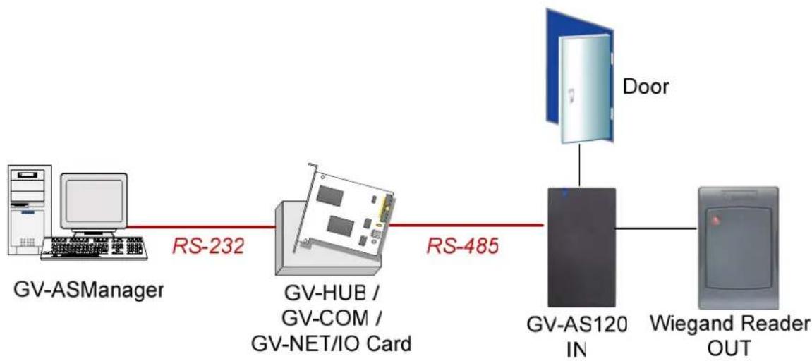
flowchart
graph LR
    A["GV-ASManager"] -->|RS-232| B["GV-HUB / GV-COM / GV-NET/IO Card"]
    B -->|RS-485| C["GV-AS120 IN"]
    C --> D["Door"]
    C --> E["Wiegand Reader OUT"]
Figure 3-1
GV-AS120 can make network connection to GV-ASManager using the optional GV-ASBox or GV-ASNet. With GV-ASBox, two-door control is also possible as illustrated below.
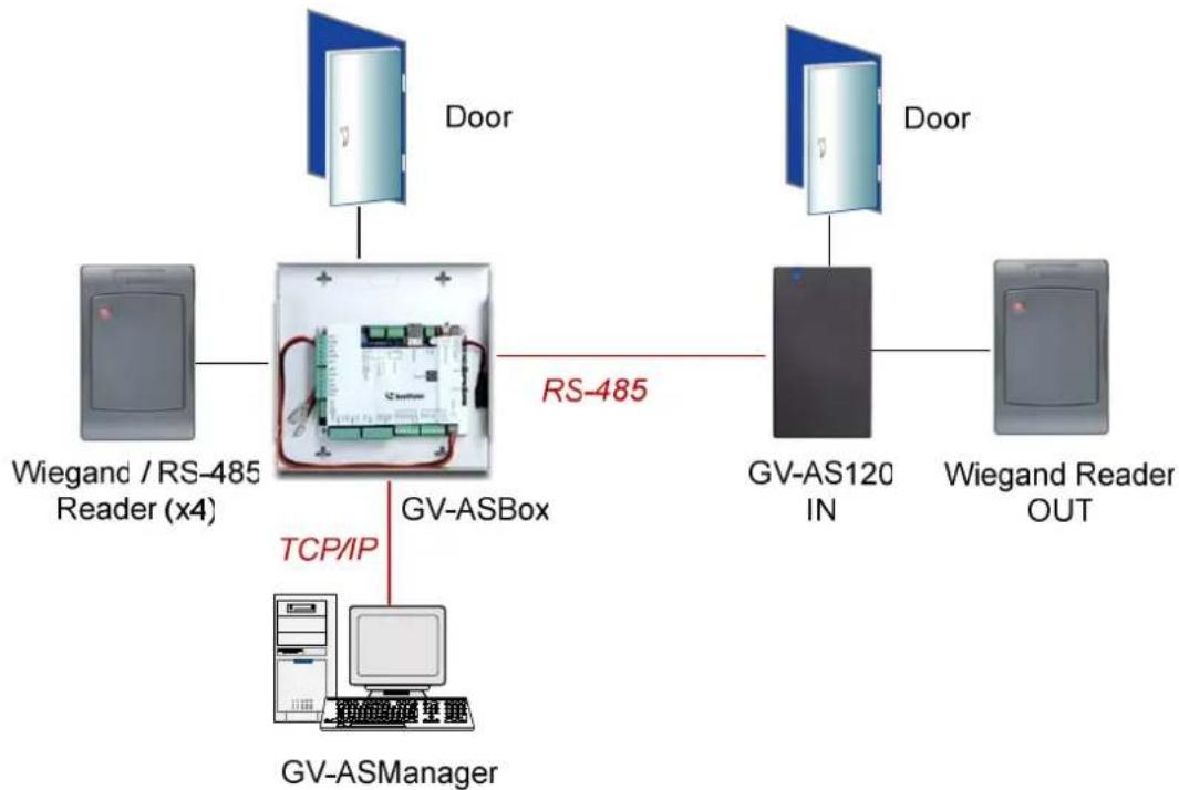
flowchart
graph TD
    A["Wiegand / RS-485 Reader (x4)"] --> B["GV-ASBox"]
    B -->|RS-485| C["GV-AS120 IN"]
    C --> D["Wiegand Reader OUT"]
    B -->|TCP/IP| E["GV-ASManager"]
    B --> F["Door"]
    C --> G["Door"]
Figure 3-2 Through GV-ASBox
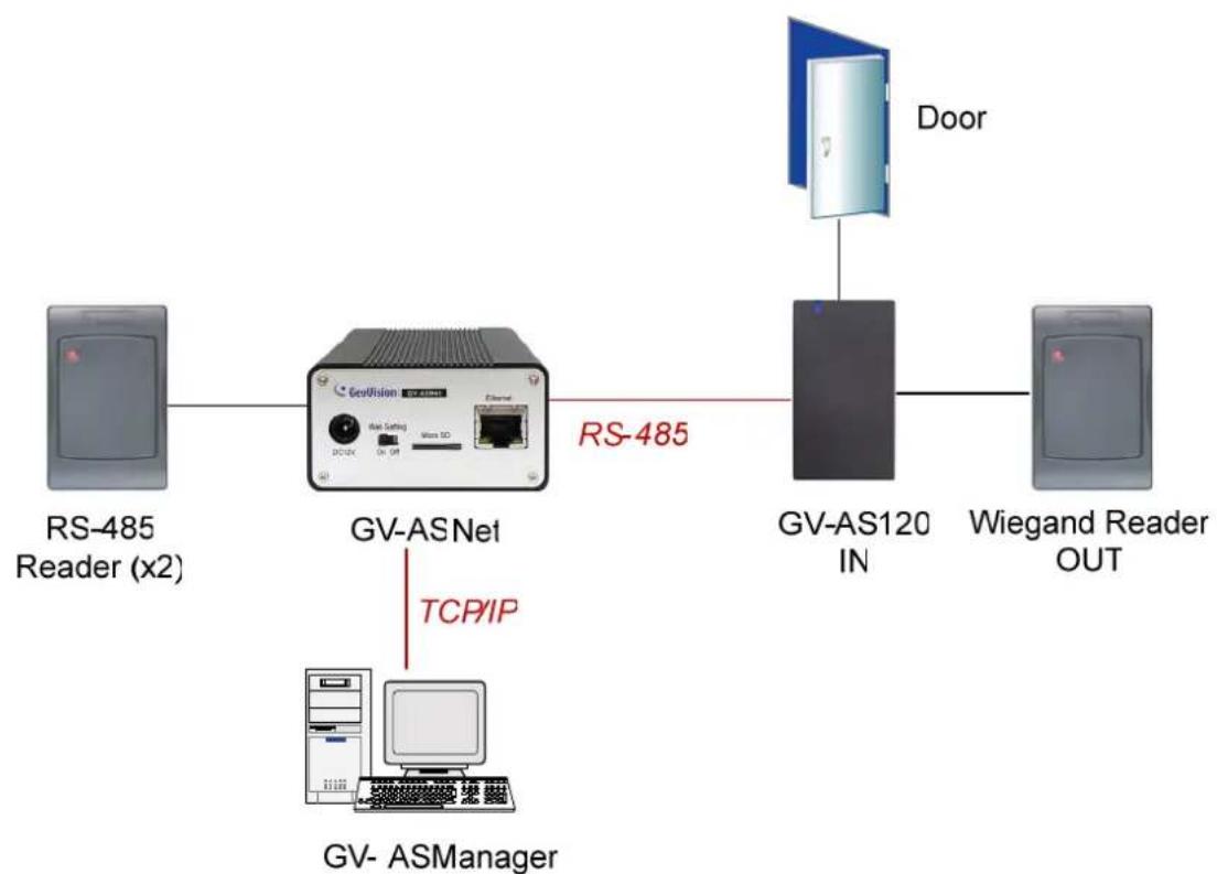
flowchart
graph LR
    A["RS-485 Reader (x2)"] --> B["GV-ASNet"]
    B -->|TCP/IP| C["GV-ASManager"]
    B --> D["GV-AS120 IN"]
    D --> E["Door"]
    E --> F["Wiegand Reader OUT"]
Figure 3-3 Through GV-ASNet
3.1.1 Main Features
- 1 door (one-way and two-way control), expandable to 2 doors with optional GV-ASBox
• 1,000 / 40,000 cards (standalone / networked or RS-485 mode)
• Built-in 2 digital inputs and 1 relay output - 1 Wiegand output (26 \~ 64 bits) for extra reader programming
• Built-in 13.56MHz Reader
• Built-in tampering alarm sensor - Weather-proof and IP66-compliant housing (for outdoor use)
3.1.2 Packing List
GV-AS120
- Power Cord
- Screw x 3
- Screw Anchor x 2
- Security Torx
- Enroll Card
- Delete Card
• GV-AS ID F Card x 20
- Software CD
• Power Adaptor 12V DC / 1.25A
3.2 Installation
The wire assignment of the GV-AS120 cable data are illustrated below.
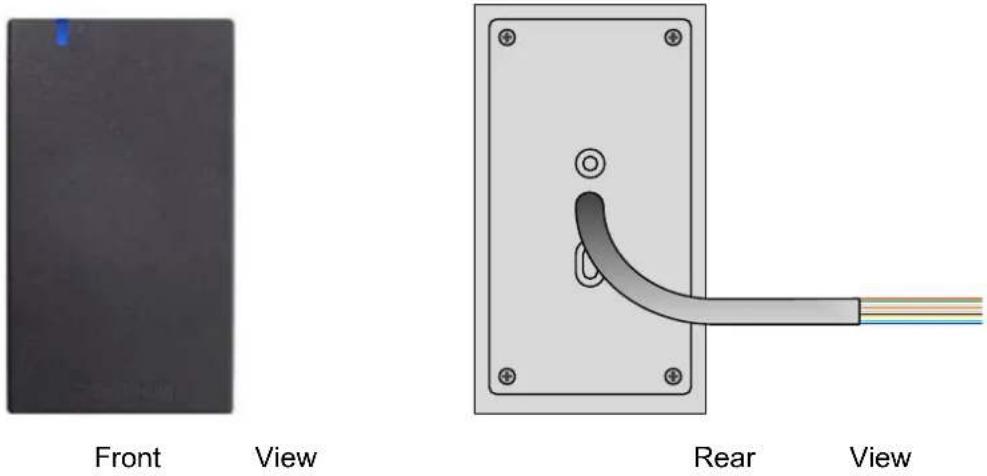
Figure 3-4
| Wire color Definition | |
| Red | 12V |
| Black | GND |
| Green Wiegand | Data 0 |
| White Wiegand | Date 1 |
| Blue | RS485+ |
| Light Blue RS485- | |
| Brown IN COM (GND) | |
| Yellow Door Sensor IN1 | |
| LRed | Button IN2 |
| Purple | Door COM |
| Orange | Door NC |
| Gray | Door NO |
3.2.1 Connecting a Wiegand Reader
GV-AS120 provides one Wiegand input for connection to the Wiegand reader ranging from 26 to 64 bits. Through the Web interface of GV-AS120, you can set the Wiegand reader as the entry or exit reader. To define the reader, see 9.3.2.A Function Setting.
The table below shows the wire assignments of the Wiegand input on GV-AS120. Please consult the documentation of your Wiegand reader for wiring. You will need to set up a separate power source to power the Wiegand reader.
| Wire color Definition | |
| Green Wiegand Data 0 | |
| White Wiegand Date 1 |
3.2.2 Connecting Input Devices
GV-AS120 supports 2 types of inputs:
- Sensor inputs, e.g. door status
- Button inputs, e.g. door opener
All inputs are dry contact and can be configured as normally open (NO) or normally closed (NC) through the GV-AS120 Web interface. The default value is NO. To change the input status, see 9.3.2.F In/Out Function.
The table below shows the wire assignments of input connectors on GV-AS120.
| Wire color Definition | ||
| Yellow Door | Sensor IN1 | |
| LRed | Button | IN2 |
| Brown IN COM (GND) | ||
3.2.3 Connecting Output Devices
GV-AS120 supports 1 type of output: Door outputs, e.g. electronic lock
The table below shows the wire assignments of output connectors on GV-AS120.
| Wire color Definition | ||
| Purple | Door | COM |
| Orange | Door | NC |
| Gray | Door | NO |
Check if your output device meets the following absolute maximum ratings before connecting it to the Door outputs.
| Breakdown Voltage | 250V AC, 220V DC |
| Continuous Load Current | 1A (30V DC), 0.3A (125V AC) |
| Note: Absolute Maximum Ratings are those values beyond which damage to GV-AS120 circuit board may occur. Continuous operation of GV-AS120 at the absolute rating level may affect GV-AS120's reliability. | |
To connect an output device:
The example below illustrates the connection of a locking device to GV-AS120. Connect the (+) point on the locking device to the Door COM wire on GV-AS120, connect the two (-) points of the locking device and the external power supply together, and connect the (+) point on the external power supply to the Door NO or Door NC wire on GV-AS120 based on the state of the locking device.
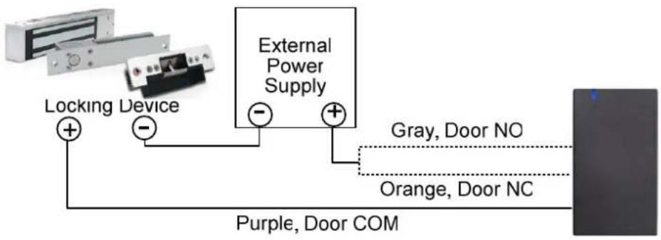
Figure 3-5
3.2.4 Connecting to the PC
The computer running GV-ASManager software can be used to monitor the access information and alarm messages from GV-AS120. The communication link between the computer and GV-AS120 can be either through RS-485 or network. For RS-485 connection, a RS-485 to RS-232 converter is required, such as a GV-Hub, GV-COM or GV-NET/ IO Card V3.1. For network connection, an optional GV-ASBox or GV-ASNet is required.
3.2.4.A RS-485 Connection
The figure below illustrates the RS-485 connection to the computer. For this connection, a RS-485 to RS-232 converter between GV-AS120 and the computer is required. You can use GV accessories, such as GV-Hub, GV-COM and GV-NET/IO Card, as the RS-485/RS-232 converter.
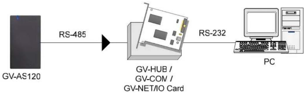
flowchart
graph LR
    A["GV-AS120"] -->|RS-485| B["GV-HUB / GV-CON / GV-NET/IO Card"]
    B -->|RS-232| C["PC"]
Figure 3-6
The table shows the wire assignments of RS-485 connection on GV-AS120.
| Wire color Definition | ||
| Blue | RS485 | A+ |
| Light Blue RS485 A- | ||
To define ID number, control type and authentication mode
Using the GV-AS120 Setting AP in the GV-ASManager folder, you can define the ID number of multiple GV-AS120 connected through RS-485 interface, as well as set the control type and authentication mode.
- Go to C:\Access Control\ASManager\ and double-click GV-AS120 SetupAP V100.exe. This dialog box appears.
Figure 3-7
- Select the COM port that is connected to GV-AS120 and click Open COM. The red square should change to blue to indicate the COM port is correct.
Note: To verify the COM port that is connected to GV-AS120, go to Windows Device Manager. In the Ports (COM & LPT) field, you should see the entry for Prolific USB-to-Serial Comm Port. The COM port shown in parenthesis indicates the COM number currently in use.
-
Select an ID number for the GV-AS120.
-
Use the drop-down list to define the Control Type and Authentication Mode. Refer to Door / Gate Function and Set Authentication Mode in 2.3.2 Programming the GV-AS110 for more details on each type of Control Type and Authentication Mode.
-
Click Setup GO. The settings are sent to GV-AS120.
3.2.4.B Network Connection
The figure below illustrates the network connection to the computer. For this connection, a GV-ASBox or GV-ASNet is required.
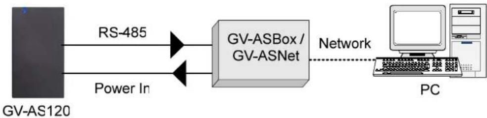
flowchart
graph LR
    A["GV-AS120"] -->|RS-485| B["GV-ASBox / GV-ASNet"]
    A -->|Power In| B
    B -->|Network| C["PC"]
Figure 3-8
Connect two power wires and two RS-485 wires from GV-AS120 to GV-ASBox / GV-ASNet. The table below shows the wire assignments of RS-485 connection on GV-AS120.
| Wire color Definition | |
| Red | 12V |
| Black | GND |
| Blue | RS485 A+ |
| Light Blue RS4 | 85 A- |
See 9.1.4.A Connecting GV-AS100 / 110 / 120 or 9.2.4A Connecting GV-AS100 / 110 / 120 to see how to connect to GV-ASBox or GV-ASNet.
3.2.5 Connecting the Power
The supplied AC adaptor can be connected to any power source supplying from 100 to 240V. Connect 12V and GND wires to the supplied power adapter and then connect the power adapter to a power source. The table below shows the pin assignments of the power connectors on GV-AS120.
| Wire color Definition | |
| Red | 12V |
| Black | GND |
Note: Power should only be applied to the unit when all connections are completed and tested.
3.3 Programming Mode
After powering on GV-AS120, you must create two cards first, an Enroll Card and a Delete Card. The Enroll Card is used for adding new cards and the Delete Card is used for deleting cards. Either card will allow you to program the various configurations on GV-AS120.
Note: The card complying with ISO 14443A standard for smart card technology can be formatted as an Enroll Card or Delete Card.
To create the Enroll Card and the Delete Card:
- Power on the unit. The LED flashes blue.
- Present a card to be the Enroll Card.
- Present a card to be the Delete Card.
- The GV-AS120 will automatically load default, and the LED will flash blue and yellow. After 1 to 2 minutes, the LED should be a constant blue light to indicate READY.
3.3.1 Adding and Deleting Cards
Using the two cards, you can add new cards to GV-AS120 and delete existing cards on GV-AS120.
Note:
- GV-ASManager cannot manage the cards enrolled on GV-AS120, since the card data will not be transmitted to GV-ASManager.
- The cards added through GV-ASManager cannot be deleted on GV-AS120.
3.3.1.A Adding a Card
Up to 1,000 cards can be enrolled on GV-AS120 directly without needing additional software. When working with GV-ASManager software, GV-AS120 can support up to 40,000 cards.
- Present the Enroll Card.
- Present the card you want to add to the GV-AS120.
- The GV-AS120 will produce a long beep if the card has been added successfully and three short beeps if the adding procedure has failed.
The default password will be 1234 and the card will automatically be set to a Normal Card. You can change the password and set the card to different card types such as Patrol Card or Two-person A/B Card using GV-ASManager. Refer to the Adding Cards section in GV-ASManager User's Manual for more details.
Note: GV-AS120 does not support cards set up as Security Cards.
3.3.1.B Deleting a Card
- Present the Delete Card.
- Present the card you want to delete.
- The GV-AS120 will produce a long beep if the card has been deleted successfully and three short beeps if the deleting procedure has failed.
3.4 LED Status and Beeper
Normally, the LED on GV-AS120 is blue during standby mode and the LED flashes green when a card is granted access or when the operation was successful. A red LED indicates access denied or the operation was unsuccessful. The LED status and beeper under different conditions are listed below.
| Condition LED Beeper | ||
| Card Mode Constant blue | Silent | |
| Release Mode Flashes green Silent | ||
| Force Unlock Mode Flashes green Silent | ||
| Force Lock Mode Flashes red Silent | ||
| Tamper / Forced Open Alarm | Flashes green and red Constant beep until alarm cancelled | |
| Held Open Alarm Unchanged | Constant beep until alarm cancelled | |
| Access Denied Alarm Flashes red momentarily Short beep for the number of seconds specified | ||
| Access Denied Flashes red momentarily Two short beeps | ||
| Access Granted | Flashes green momentarily | One short beep |
| Enroll Card | Flashes green momentarily | Two long beeps |
| Delete Card | Flashes red momentarily Two long beeps | |
| Enrolled/Deleted card successfully | Displays green LED momentarily | One long beep |
| Enroll/Delete card failed | Displays red LED momentarily | Three short beeps |
| Firmware update | Flashes red, green and blue | Silent |
| Firmware update failed | Flashes purple | Constant beep |
| Factory default | Flashes blue | Silent |
3.5 Web-Based Configurations
Through GV-ASBox or GV-ASNet, GV-AS120 can communicate with GV-ASManager over the network. Using GV-ASBox or GV-ASNet, you can also access the Web interface of GV-AS120.
Refer to Chapter 9 Optional Devices to see how to connect a GV-ASBox or GV-ASNet and how to access the Web interface of GV-AS120.
3.6 GV-AS120 Specifications
| CPU 32-bit RISC microprocessor | ||
| Number of User Cards | 1,000 / 40,000 cards (standalone / networked or RS-485 mode) | |
| Frequency | 13.56 MHz for ISO14443A (Mifare DESFire, Mifare Plus and Mifare Classic) | |
| Event Buffer 65,536 events and log data | ||
| Power 100 ~ 240V AC, 50 ~ 60 Hz | ||
| Wiegand Interface | 1 Wiegand interface, 26 ~ 64 bit format | |
| 12V DC Power Supply, 200mA | ||
| Communication Protocol RS-485 | ||
| Digital I/O | Input 2 inputs, dry contact, NO / NC | |
| Output 1 output | ||
| Supported ID Format Built-in reader reads UID only | ||
| Operating Temperature -35 ~ 65°C / -31 ~ 149°F | ||
| Operating Humidity 10% ~ 90% RH (non-condensing) | ||
| Dimensions (W X H X D) 65.8 x 115.6 x 20.5 mm / 2.6 x 4.6 x 0.8 in | ||
| Weight 138 g / 0.3 lb | ||
| Ingress Protection IP66 | ||
| Certification CE, FCC, RoHS | ||
All specifications are subject to change without notice.
- GV-AS210 / 2110 Controller
4.1 Introduction
4.1.1 Main Features
• One-way control: 4 doors
- Two-way control: 2 doors by Wiegand only, 4 doors by Wiegand, RS-485 and network
• Support 4 Wiegand card readers of 26 to 64 bits
- Support 8 GV-Readers / GV-GF Fingerprint Readers through RS485 connection
• Built-in 8 digital inputs and 8 relay outputs
- Suitable for door, doors, parking gates and access to elevator call buttons
• Support for tampering alarm
4.1.2 Packing List
• GV-AS210 / 2110
• Power Adaptor 12V DC / 3A
- Power Cord
- Battery Cable
- Micro SD Card 2 GB
- Software CD
4.1.3 GV-AS210 / 2110 Board Layout
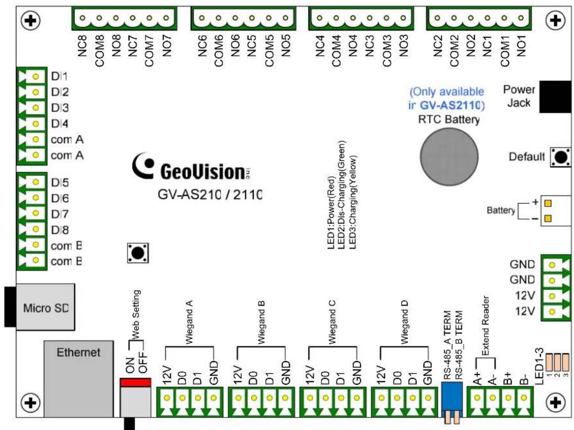
Figure 4-1
4.2 Installation
4.2.1 Connecting Card Readers
GV-AS210 / 2110 supports two types of card reader interfaces:
- Wiegand: Compatible with any Wiegand card readers of 26 to 64 bits.
• RS-485: Only compatible with all GV-Readers and GV-GF Fingerprint Readers.
4.2.1.A Wiegand Readers
GV-AS210 / 2110 provides 4 Wiegand inputs (Wiegand A to Wiegand D). Connect up to 4 Wiegand readers ranging from 26 to 64 bits to the Wiegand interfaces. Please consult the documentation of your Wiegand reader for wiring.
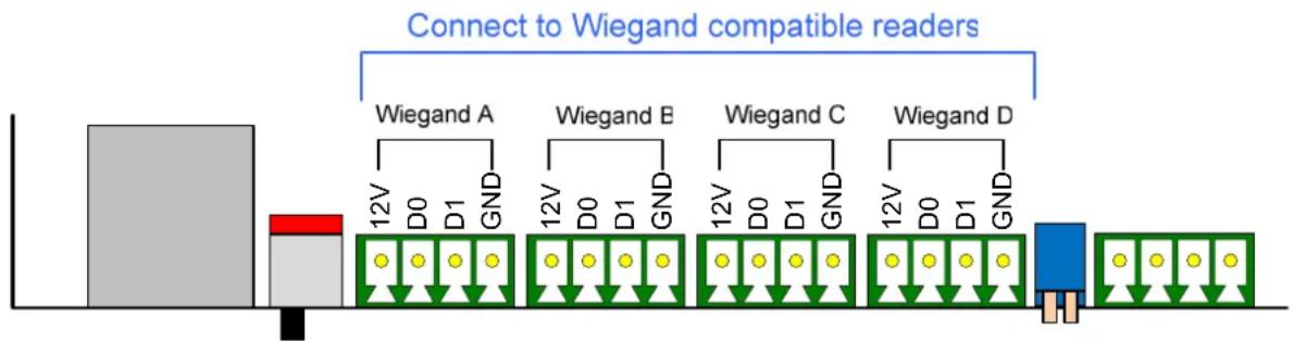
flowchart
graph LR
    A["Start"] --> B["Wiegand A"]
    B --> C["12V D0 GND"]
    C --> D["Wiegand E"]
    D --> E["12V D0 GND"]
    E --> F["Wiegand C"]
    F --> G["12V D0 GND"]
    G --> H["Wiegand D"]
    H --> I["End"]
Figure 4-2
4.2.1.B RS-485 Readers
For long-distance connection and non-Wiegand card readers, you can establish RS-485 connection with any GV-Readers and GV-GF Fingerprint Readers. Up to 8 readers can be connected together with a single RS-485 cable to the RS-485 interface on GV-AS210 / 2110.
When multiple readers are connected together, an extra power supply to each unit is required. Use 12V power output and GND on the power terminal or the Wiegand connectors to power on each unit.
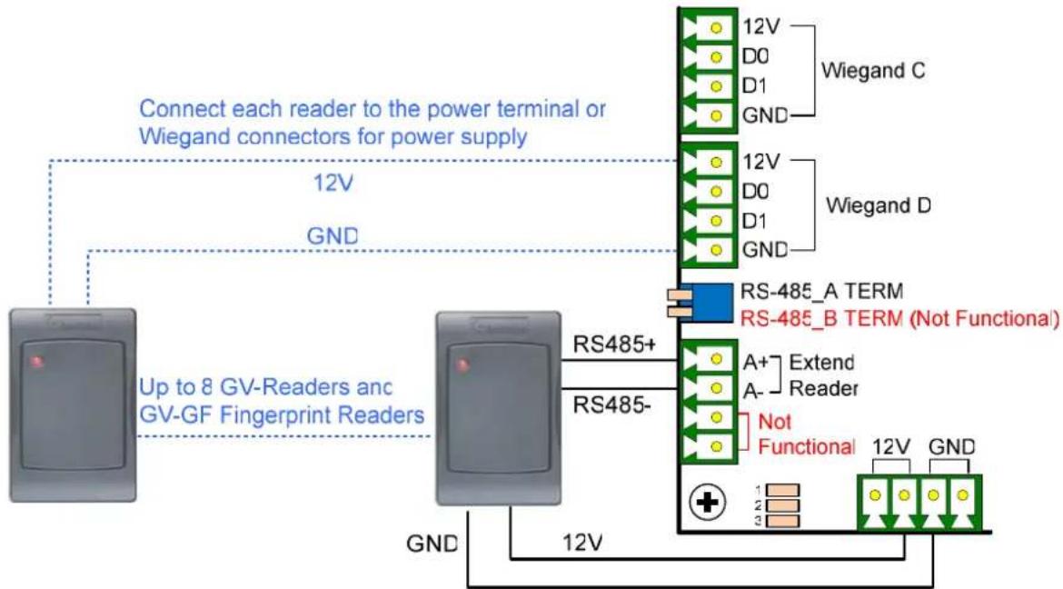
flowchart
graph TD
    A["Power Terminal"] -->|Connect each reader to the power terminal or Wiegand connectors for power supply| B["Wiegand C"]
    A -->|Connect each reader to the power terminal or Wiegand connectors for power supply| C["Wiegand D"]
    A -->|Connect each reader to the power terminal or Wiegand connectors for power supply| D["RS485_A TERM"]
    A -->|Connect each reader to the power terminal or Wiegand connectors for power supply| E["RS485_B TERM (Not Functional)"]
    A -->|Connect each reader to the power terminal or Wiegand connectors for power supply| F["RS485-"]
    A -->|Connect each reader to the power terminal or Wiegand connectors for power supply| G["RS485+"]
    A -->|Connect each reader to the power terminal or Wiegand connectors for power supply| H["RS485-"]
    A -->|Connect each reader to the power terminal or Wiegand connectors for power supply| I["Not Functional"]
    A -->|Connect each reader to the power terminal or Wiegand connectors for power supply| J["12V"]
    A -->|Connect each reader to the power terminal or Wiegand connectors for power supply| K["12V"]
    A -->|Connect each reader to the power terminal or Wiegand connectors for power supply| L["12V"]
    A -->|Connect each reader to the power terminal or Wiegand connectors for power supply| M["12V"]
    A -->|Connect each reader to the power terminal or Wiegand connectors for power supply| N["12V"]
    A -->|Connect each reader to the power terminal or Wiegand connectors for power supply| O["12V"]
    A -->|Connect each reader to the power terminal or Wiegand connectors for power supply| P["12V"]
    A -->|Connect each reader to the power terminal or Wiegand connectors for power supply| Q["12V"]
    A -->|Connect each reader to the power terminal or Wiegand connectors for power supply| R["12V"]
    A -->|Connect each reader to the power terminal or Wiegand connectors for power supply| S["12V"]
    A -->|Connect each reader to the power terminal or Wiegand connectors for power supply| T["12V"]
    A -->|Connect each reader to the power terminal or Wiegand connectors for power supply| U["12V"]
    A -->|Connect each reader to the power terminal or Wiegand connectors for power supply| V["12V"]
    A -->|Connect each reader to the power terminal or Wiegand connectors for power supply| W["12V"]
    A -->|Connect each reader to the power terminal or Wiegand connectors for power supply| X["12V"]
    A -->|Connect each reader to the power terminal or Wiegand connectors for power supply| Y["12V"]
    A -->|Connect each reader to the power terminal or Wiegand connectors for power supply| Z["12V"]
    A -->|Connect each reader to the power terminal or Wiegand connectors for power supply| AA["12V"]
    A -->|Connect each reader to the power terminal or Wiegand connectors for power supply| AB["12V"]
    A -->|Connect each reader to the power terminal or Wiegand connectors for power supply| AC["12V"]
    A -->|Connect each reader to the power terminal or Wiegand connectors for power supply| AD["12V"]
    A -->|Connect each reader to the power terminal or Wiegand connectors for power supply| AE["12V"]
    A -->|Connect each reader to the power terminal or Wiegand connectors for power supply| AF["12V"]
    A -->|Connect each reader to the power terminal or Wiegand connectors for power supply| AG["12V"]
    A -->|Connect each reader to the power terminal or Wiegand connectors for power supply| AH["12V"]
    A -->|Connect each reader to the power terminal or Wiegand connectors for power supply| AI["12V"]
    A -->|Connect each reader to the power terminal or Wiegand connectors for power supply| AJ["12V"]
    A -->|Connect each reader to the power terminal or Wiegand connectors for power supply| AK["12V"]
    A -->|Connect each reader to the power terminal or Wiegand connectors for power supply| AL["12V"]
    A -->|Connect each reader to the power terminal or Wiegand connectors for power supply| AM["12V"]
    A -->|Connect each reader to the power terminal or Wiegand connectors for power supply| AN["12V"]
    A -->|Connect each reader to the power terminal or Wiegand connectors for power supply| AO["12V"]
    A -->|Connect each reader to the power terminal or Wiegand connectors for power supply| AP["12V"]
    A -->|Connect each reader to the power terminal or Wiegand connectors for power supply| AQ["12V"]
    A -->|Connect each reader to the power terminal or Wiegand connectors for power supply| AR["12V"]
    A -->|Connect each reader to the power terminal or Wiegand connectors for power supply| AS["12V"]
    A -->|Connect each reader to the power terminal or Wiegand connectors for power supply| AT["12V"]
    A -->|Connect each reader to the power terminal or Wiegand connectors for power supply| AU["12V"]
    A -->|Connect each reader to the power terminal or Wiegand connectors for power supply| AV["12V"]
    A -->|Connect each reader to the power terminal or Wiegand connectors for power supply| AW["12V"]
    A -->|Connect each reader to the power terminal or Wiegand connectors for power supply| AX["12V"]
    A -->|Connect each reader to the power terminal or Wiegand connectors for power supply| AY["12V"]
    A -->|Connect each reader to the power terminal or Wiegand connectors for power supply| AZ["12V"]
Figure 4-3
Note:
- Each set of 12V power output and GND can provide power for up to 2 readers. The 2 sets on the power terminal can support up to 4 readers. If you wish to connect more readers and the Wiegand interfaces are already occupied, you can connect the readers to external power source.
- When the RS-485 connection between GV-AS210 / 2110 and the reader is over 600 meters, turn ON the RS485 A Terminal switch to avoid unstable signals.
4.2.2 Connecting Input Devices
Up to 8 input devices can be connected to GV-AS210 / 2110. Connect the input wires to DI1\~8 and connect GND wires to com.A or com.B. Multiple GND wires can be connected to the same com.A/B interface.
All inputs are dry contact that can be configured as normally open (NO) or normally closed (NC) on the Web interface. To change the input status, refer to 8.2.6 Input Configuration.
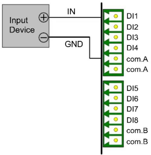
flowchart
graph TD
    A["Input Device"] -->|IN| B["Output Lines"]
    A -->|-| C["GND"]
    C --> D["Output Lines"]
    style A fill:#f9f,stroke:#333
    style B fill:#ccf,stroke:#333
    style C fill:#cfc,stroke:#333
    style D fill:#fcc,stroke:#333
Figure 4-4
4.2.3 Connecting Output Devices
Up to 8 output devices can be connected to GV-AS210 / 2110. Check if your output device meets the following absolute maximum ratings before connecting it to outputs 1 \~ 8.
| Breakdown Voltage | 110V AC ~ 250V AC, 30V DC |
| Continuous Load Current | 3A (AC), 3A (DC) |
| Note: Absolute Maximum Ratings are those values beyond which damage to GV-AS210 / 2110 circuit board may occur. Continuous operation of GV-AS210 / 2110 at the absolute rating level may affect GV-AS210 / 2110 reliability. | |
To connect an output device:
Connect the (+) point on the output device to COM on GV-AS210 / 2110, connect the two (-) points of the output device and the external power supply together, and connect the (+) point on the external power supply to the NO or NC of GV-AS210 / 2110 based on the state of the output device.
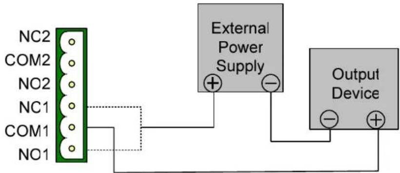
Figure 4-5
Note: If instead of connecting an external power supply, you want to connect the output devices to the power outputs on the GV-AS210 / 2110, note that the maximum current of the voltage output is 12V, 0.9A.
4.2.4 Connecting Backup Battery
You can connect any battery of 12V 12Ah to GV-AS210 / 2110 to provide backup power when the main power supply fails. When the main power supply is removed and the battery voltage level is above 10.2V, the battery will support normal operation of the controller.
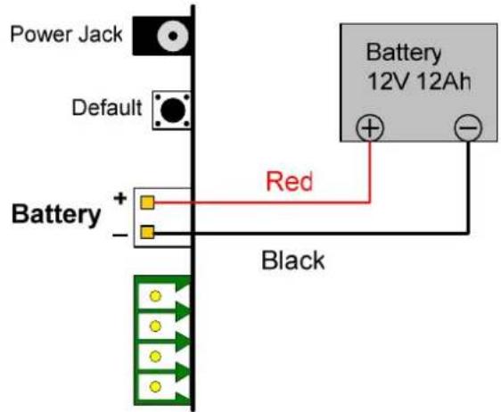
Figure 4-6
4.2.5 Connecting the Power
You can connect GV-AS210 / 2110 to power directly using the supplied 12V DC adaptor. After power is connected, the power LED on GV-AS210 / 2110 should glow.
Note: Power should be applied to the unit when all connections are completed and tested.
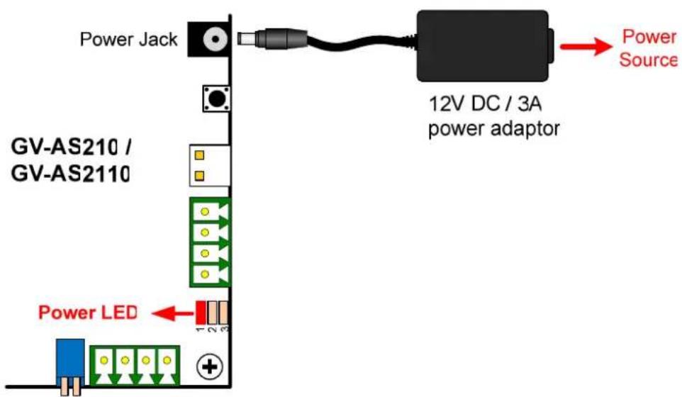
Figure 4-7
4.2.6 Connecting the PC
Connecting GV-AS210 / 2110 to a computer allows you to access its Web interface and connect it to GV-ASManager if the computer is installed with GV-ASManager. The computer running GV-ASManager software can be used to monitor the access information and alarm messages from GV-AS210 / 2110. If connection with GV-ASManager is interrupted, GV-AS210 / 2110 stores this information on the supplied micro SD card. The data stored will be sent to GV-ASManager when connection resumes.
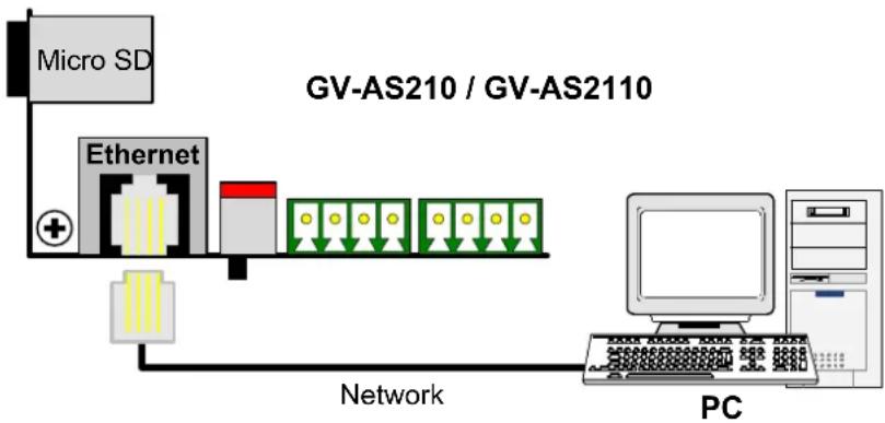
flowchart
graph LR
    A["Micro SD"] --> B["Ethernet"]
    B --> C["Network"]
    C --> D["PC"]
    style A fill:#f9f,stroke:#333
    style B fill:#ccf,stroke:#333
    style C fill:#cfc,stroke:#333
    style D fill:#fcc,stroke:#333
Figure 4-8
Note: GV-AS210 is only compatible with GV-ASManager V4.0 or later, and GV-AS2110 is only compatible with GV-ASManager V4.2.3 or later.
4.2.7 Fitting the Battery (GV-AS2110 Only)
GV-AS2110 includes a replaceable cell button battery. When the power in the battery becomes low, a "Low Battery" message and icon will appear in GV-ASManager. When this happens, replace the battery. All settings on GV-AS2110 will disappear about 10 hours after the battery stops working, and GV-AS2110 will be restored to default settings.
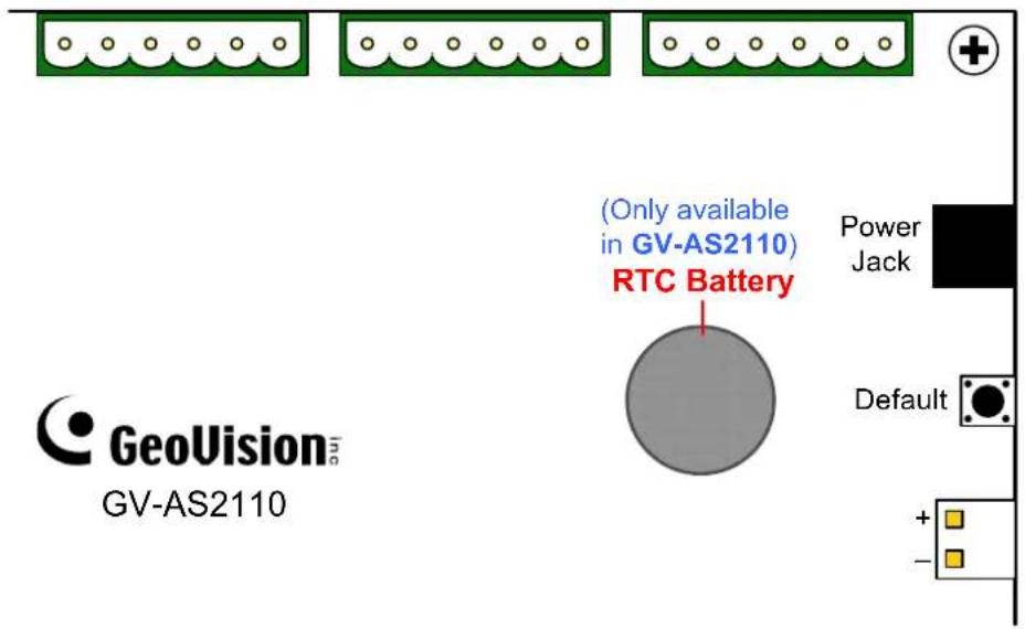
Figure 4-9
Note:
- Make sure the plastic insulation film under the battery is removed.
- It is recommended to replace the battery annually.
4.3 Other Settings
4.3.1 Web Setting Switch
When the Web Setting switch is set to the ON position, you can modify Advanced Settings and Extended Reader of GV-AS210 / 2110 through its Web interfaces. When the switch is set to the OFF position, Advanced Settings are not accessible. For details on Advanced Settings, see 8.2 Advanced Settings.
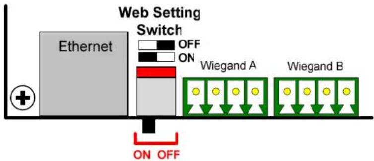
flowchart
graph LR
    A["Ethernet"] -->|ON| B["Wiegand A"]
    A -->|OFF| C["Wiegand B"]
    style A fill:#ccc,stroke:#333
    style B fill:#999,stroke:#333
    style C fill:#ccc,stroke:#333
Figure 4-10
4.3.2 Resetting the GV-AS210 / 2110
To reset GV-AS210 / 2110, press the Reset button in the lower left of GV-AS210 / 2110 circuit board for three seconds.
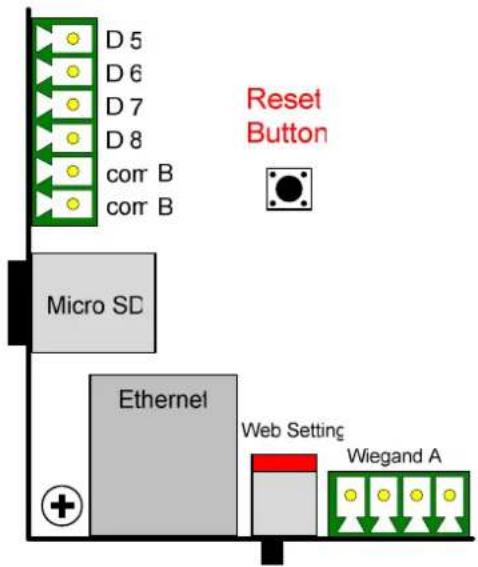
Figure 4-11
4.3.3 Restoring Factory Defaults
To restore GV-AS210 / 2110 to factory default settings, press the Default button for 10 seconds.
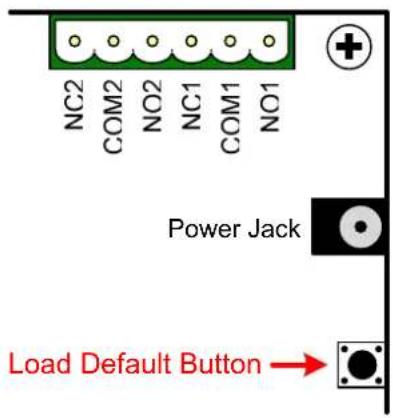
Figure 4-12
4.4 The Web Interface
You can install GV-AS210 / 2110 on a network and configure GV-AS210 / 2110 through its Web interface.
Refer to Chapter 7 Installing on a Network for detailed instructions on setting a fixed or dynamic IP address to access GV-AS210 / 2110.
Refer to Chapter 8 The Web Interface for details on the setup pages of the Web interface. Through the Web interface, you can configure general settings, input/output devices, associated doors/gates and connected readers.
4.5 GV-AS210 / AS2110 Specifications
| GV-AS210 GV-AS2110 | ||
| CPU 32-bit ARM7TDMI | ||
| Number of User Cards 40,000 cards | ||
| Event Buffer 1,000,000 events and log data | ||
| Power 100~250V AC, 50~60 Hz | ||
| RS-485 Interface | 1 RS-485 interface only for GV-Readers and GV-GF Fingerprint Readers (max. 8 readers) | |
| Wiegand Interface | 4 Wiegand interfaces, 26 ~ 64 bit format | |
| 12V DC power supply, 200mA | ||
| TCP/IP Interface 1 TCP/IP interface for GeoVision network readers | ||
| Communication Protocol TCP/IP | ||
| Battery Built-in battery Replaceable button cell | ||
| Input 8 inputs, dry contact, NO/NC | ||
| Output 8 relay outputs (30V DC, 3A; 110V AC ~ 250V AC, 3A) | ||
| Operating Temperature 0 ~ 65°C / 32 ~ 149°F | ||
| Operating Humidity 10% ~ 90% RH (non-condensing) | ||
| Dimensions (W X H X D) 210 x 204 x 46.6 mm / 8.27 x 8.03 x 1.83 in (case included) | ||
| Weight | 810 g / 1.79 lb (case included) | |
| Certification | CE, FCC, RoHS | |
All specifications are subject to change without notice.
- GV-AS410 / 4110 / 810 / 8110 Controller
5.1 Introduction
5.1.1 Main Features
GV-AS410 / 4110
• One-way control: 4 doors
- Two-way control: 4 doors
• Support 8 Wiegand card readers of 26 to 64 bits
- Support 8 GV-Readers / GV-GF Fingerprint Readers through RS485 connection / Network
• Built-in 16 digital inputs and 24 relay outputs
- Suitable for doors, parking gates and access to elevator call buttons
• Support for tampering alarm
GV-AS810 / 8110
• One-way control: 8 doors
- Two-way control: 4 doors by Wiegand only, 8 doors by Wiegand / RS-485 / Network
• Support 8 Wiegand card readers of 26 to 64 bits
- Support 16 GV-Readers / GV-GF Fingerprint Readers through RS485 connection / Network
• Built-in 16 digital inputs and 24 relay outputs
- Suitable for doors, parking gates and access to elevator call buttons
• Support for tampering alarm
5.1.2 Packing List
• GV-AS410 / 4110 / 810 / 8110
• GV-AS410 / 4110: Power Adaptor 12V DC / 3.5A
GV-AS810 / 8110: Power Adaptor 12V DC / 5A
- Power Cord
- Battery Cable
- Micro SD Card 2 GB
- Software CD
5.1.3 GV-AS410 / 4110/ 810 / 8110 Board Layout
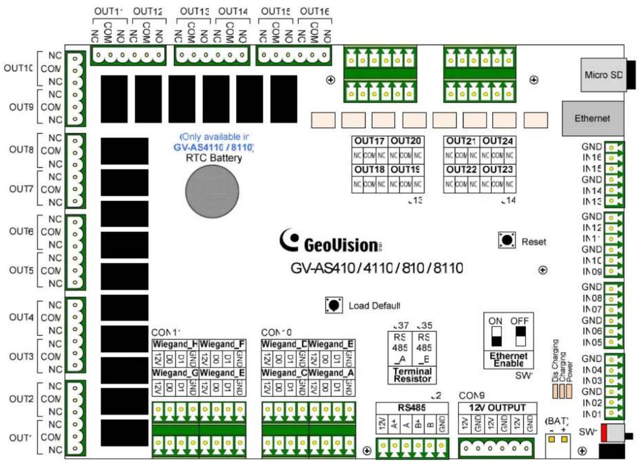
Figure 5-1
5.2 Installation
5.2.1 Connecting Card Readers
GV-AS410 / 4110 / 810 / 8110 supports two types of card reader interfaces:
- Wiegand: Compatible with any Wiegand card readers of 26 to 64 bits.
• RS-485: Only compatible with all GV-Readers and GV-GF Fingerprint Readers.
5.2.1.A Wiegand Readers
GV-AS410 / 4110 / 810 / 8110 provides 8 Wiegand inputs (Wiegand A to Wiegand H). Connect up to 8 Wiegand readers ranging from 26 to 64 bits to the Wiegand interfaces. Please consult the documentation of your Wiegand reader for wiring.
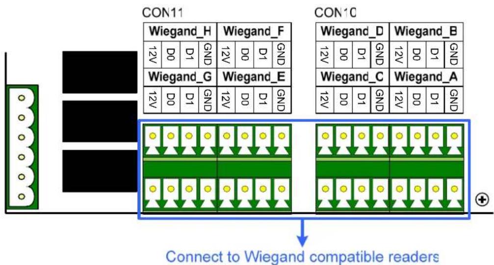
flowchart
graph TD
    subgraph CON11
        A["Wiegand_H"] --> B["12V D0 D1 GND"]
        C["Wiegand_G"] --> D["12V D0 D1 GND"]
        E["Wiegand_E"] --> F["12V D0 D1 GND"]
    end
    subgraph CON10
        G["Wiegand_D"] --> H["12V D0 D1 GND"]
        I["Wiegand_B"] --> J["12V D0 D1 GND"]
        K["Wiegand_C"] --> L["12V D0 D1 GND"]
        M["Wiegand_A"] --> N["12V D0 D1 GND"]
    end
    A --> O["Connect to Wiegand compatible readers"]
    C --> O
    E --> O
    G --> O
    I --> O
    K --> O
    M --> O
    O --> P["+"]
Figure 5-2
Note: Although 8 Wiegand inputs are available, GV-AS410 / 4110 only supports control of up to 4 doors.
5.2.1.B RS-485 Readers
For long-distance connection and non-Wiegand card readers, you can connect RS-485 connection with any GV-Readers and GV-GF Fingerprint Readers. Using a single RS-485 cable, up to 8 readers can be connected together with to the RS-485 A+ / A- interface. For GV-AS810 / 8110, another 8 readers can be connected to the RS-485 B+ / B- interface, for a total of 16 RS-485 readers.
When multiple readers are connected together, an extra power supply to each unit is required. Use 12V power output and GND on the power terminal or the Wiegand connectors to power on each unit.
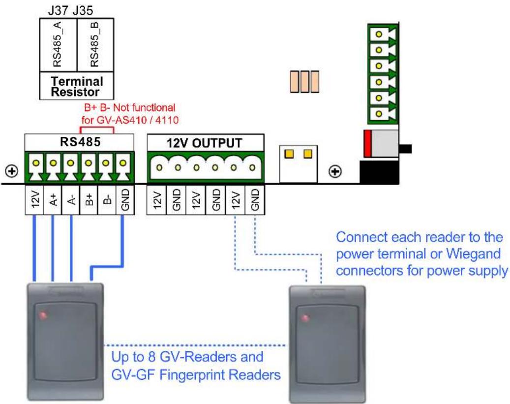
Figure 5-3
Note:
- Each set of 12V power output and GND can provide power for up to 2 readers. The 3 sets on the power terminal can support up to 6 readers. If you wish to connect more readers and the Wiegand interfaces are already occupied, you can connect the readers to external power source.
- By default, a jumper cap is installed on the RS485_A Terminal Resister (J37) to ensure stability when the RS-485 connection between GV-AS410 / 4110 / 810 / 8110 and the reader is over 600 meters.
- Although up to 8 RS-485 readers can be connected, GV-AS410 / 4110 only supports control of up to 4 doors.
5.2.2 Connecting Input Devices
Up to 16 input devices can be connected to GV-AS410 / 4110 / 810 / 8110. Connect the input wires to IN1\~16 and connect GND wires to GND. Multiple GND wires can be connected to the same GND pin.
All inputs are dry contact that can be configured as normally open (NO) or normally closed (NC) on the Web interface. To change the input status, refer to 8.2.6 Input Configuration.
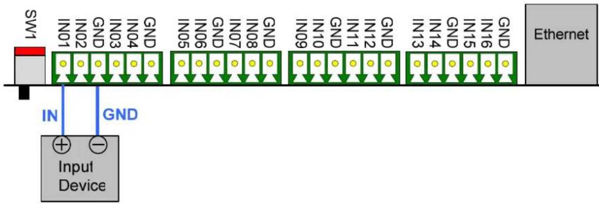
flowchart
graph LR
    SW1["SW1"] -->|IN| Device["Input Device"]
    Device -->|GND| GND1["GND"]
    GND1 -->|IN01| SW1
    GND1 -->|IN02| SW1
    GND1 -->|GND| SW1
    SW1 -->|IN03| SW1
    SW1 -->|IN04| SW1
    SW1 -->|GND| SW1
    SW1 -->|IN05| SW1
    SW1 -->|IN06| SW1
    SW1 -->|GND| SW1
    SW1 -->|IN07| SW1
    SW1 -->|IN08| SW1
    SW1 -->|GND| SW1
    SW1 -->|IN09| SW1
    SW1 -->|IN10| SW1
    SW1 -->|GND| SW1
    SW1 -->|IN11| SW1
    SW1 -->|IN12| SW1
    SW1 -->|GND| SW1
    SW1 -->|IN13| SW1
    SW1 -->|IN14| SW1
    SW1 -->|GND| SW1
    SW1 -->|IN15| SW1
    SW1 -->|IN16| SW1
    SW1 -->|GND| SW1
    SW1 -->|Ethernet| Ethernet
Figure 5-4
5.2.3 Connecting Output Devices
Up to 24 output devices can be connected to GV-AS410 / 4110 / 810 / 8110. Check if your output device meets the following absolute maximum ratings before connecting it to output terminal block.
| Outputs | Outputs 1-16 | Outputs 17-24 |
| Breakdown Voltage | 110V AC – 250V AC, 30V DC | 30V DC |
| Continuous Load Current | 3A (AC), 3A (DC) 1A | |
| Note: Absolute Maximum Ratings are those values beyond which damage to GV-AS410 / 4110 / 810 / 8110 circuit board may occur. Continuous operation at the absolute rating level may affect GV-AS410 / 4110 / 810 / 8110's stability. | ||
To connect an output device:
Connect the (+) point on the output device to COM on GV-AS410 / 4110 / 810 / 8110, connect the two (-) points of the output device and the external power supply together, and connect the (+) point on the external power supply to the NO or NC of GV-AS410 / 4110 / 810 / 8110 based on the state of the output device.
![OUT4 [NO COM NC OUT3 [NO COM NC] OUT2 [NO COM NC OUT1 [NO COM NC] External Power Supply Output Device](/content/2026/05/1004733/images/437b9ebf624e8d1182ea34b2dacaa690fe79b02a6d1558af710a8e5860a5c68b.jpg)
Figure 5-5
Note: If instead of connecting an external power supply, you want to connect the output devices to the power outputs on the GV-AS410 / 4110 / 810 / 8110, note that the maximum current of the voltage output is 12V, 0.9A.
5.2.4 Connecting Backup Battery
You can connect any battery of 12V 12Ah to GV-AS410 / 4110 / 810 / 8110 to provide backup power when the main power supply fails. When the main power supply is removed and the battery voltage level is above 10.2V, the Discharging LED will light and the battery will support normal operation of the GV-AS410 / 4110 / 810 / 8110.
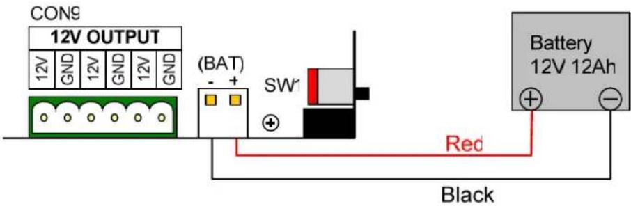
Figure 5-6
5.2.5 Connecting the Power
You can connect GV-AS410 / 4110 / 810 / 8110 to power directly using the supplied 12V DC adaptor. After power is connected, the power LED on GV-AS410 / 810 should glow.
Note: Power should only be applied to the unit when all connections are completed and tested.
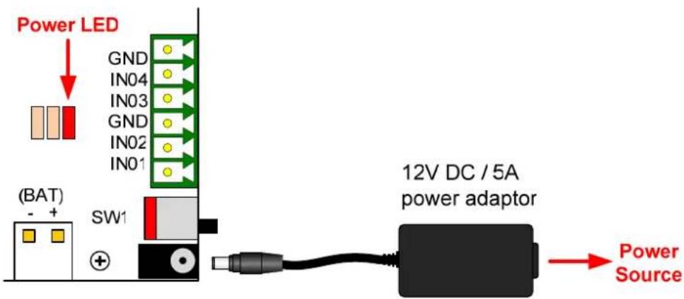
Figure 5-7
5.2.6 Connecting the PC
Connecting GV-AS410 / 4110 / 810 / 8110 to a computer allows you to access its Web interface and connect it to GV-ASManager if the computer is installed with GV-ASManager. The computer running GV-ASManager software can be used to monitor the access information and alarm messages from GV-AS410 / 4110 / 810 / 8110. If connection with GV-ASManager is interrupted, GV-AS410 / 4110 / 810 / 8110 stores this information on the supplied micro SD card. The data stored will be sent to GV-ASManager when connection resumes.
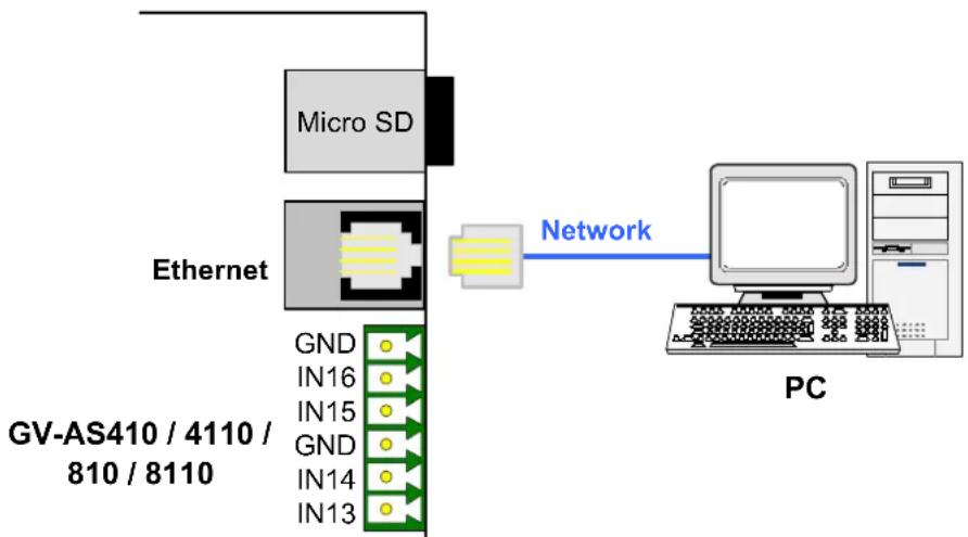
flowchart
graph TD
    A["Micro SD"] --> B["Ethernet"]
    C["GND"] --> D["IN16"]
    E["IN15"] --> F["IN15"]
    G["GND"] --> H["IN14"]
    I["IN13"] --> J["IN13"]
    K["Network"] --> L["PC"]
Figure 5-8
Note: GV-AS410 / 810 is only compatible with GV-ASManager V4.0 or later, and GV-AS4110 / 8110 is only compatible with GV-ASManager V4.2.3 or later.
5.3 Other Settings
5.3.1 Web Setting Switch
When the Web Setting switch is set to the ON position, you can modify Advanced Settings and Extended Reader settings of GV-AS410 / 4110 / 810 / 8110 through its Web interfaces. When the switch is set to the OFF position, Advanced Settings and Extended Reader settings are not accessible. For details on Advanced Settings and Extended Reader settings, see 8.2 Advanced Settings and 8.3.1 Extended Reader.
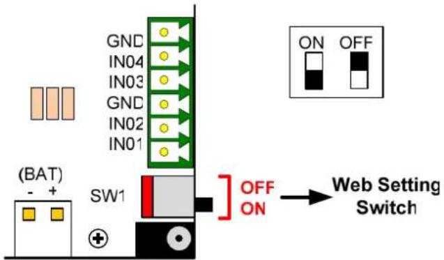
Figure 5-9
5.3.2 Resetting the GV-AS410 / 4110 / 810 / 8110
To reset GV-AS410 / 4110 / 810 / 8110, press the Reset button on the right side of GV-AS410 / 4110 / 810 / 8110 circuit board for three seconds.
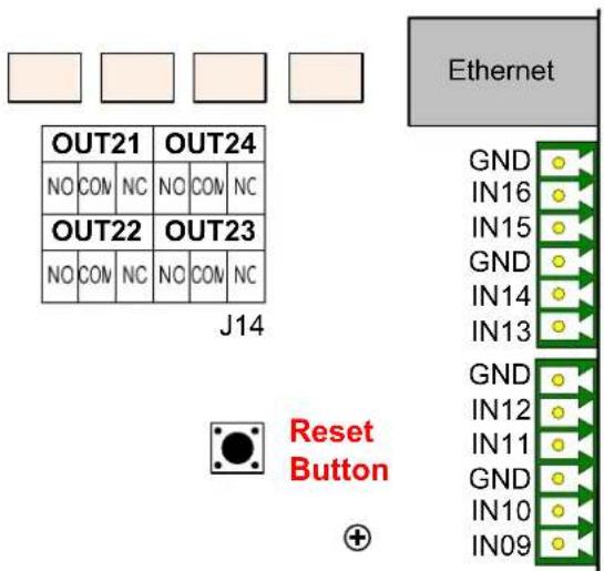
Figure 5-10
5.3.3 Restoring Factory Defaults
To restore GV-AS410 / 4110 / 810 / 8110 to factory default settings, press the Default button for 10 seconds.
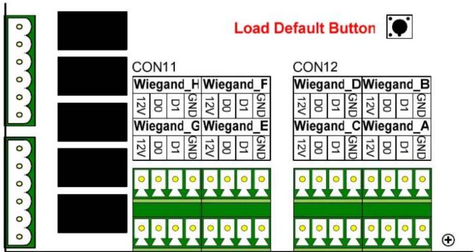
Figure 5-11
5.4 GV-AS410 / 4110 / 810 / 8110 Kit (Optional)
GV-AS410 / 4110 / 810 / 8110 Kit is a cabinet containing a GV-AS410, GV-AS4110, GV-AS810 or GV-AS8110, a power adapter board, a power supply and a casing for backup battery. The power supply provides power to GV-AS410 / 4110 / 810 / 8110 and up to 8 output devices (12V, 0.9A per device). GV-AS410 / 4110 / 810 / 8110 Kit is an optional device.
5.4.1 Packing List
- GV-AS410 Kit / GV-AS4110 Kit / GV-AS810 Kit / GV-AS8110 Kit (US standard or EU standard)
- Iron box key
- Iron box screw x 6
• Self-adhesive cable tie mounts x 6
• Power cord for battery
5.4.2 Overview
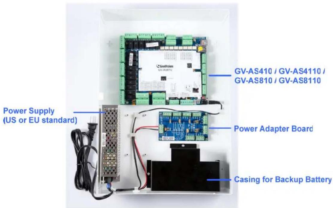
Figure 5-12
5.4.3 Connecting the GV-AS410 / 4110 / 810 / 8110 Kit
Up to 8 output devices can be powered by the power adapter board. Connect each output device to one terminal block on the board.
- Connect the COM pin on GV-AS410 / 4110 / 810 / 8110's output terminal block to the corresponding pin on the power adapter board. Connect the NC / NO pins according to the state of the output device.
![OUT2 [NO COM NC OUT1 [NO COM NC] GV-AS410 / 4110 / 810 / 8110 Power Adapter Board ED- ED+ COM NC/NO ED- ED+ COM NC/NO ED- ED+ COM NC/NO ED- ED+ COM NC/NO](/content/2026/05/1004733/images/e224e6d7f2b91eee6b56c9c0ab1da4c5859e520dd56a9909cee2755d61428825.jpg)
Figure 5-13
- Connect the ED + I - pins to the (+) and (-) points on the output device (ex: electric lock).
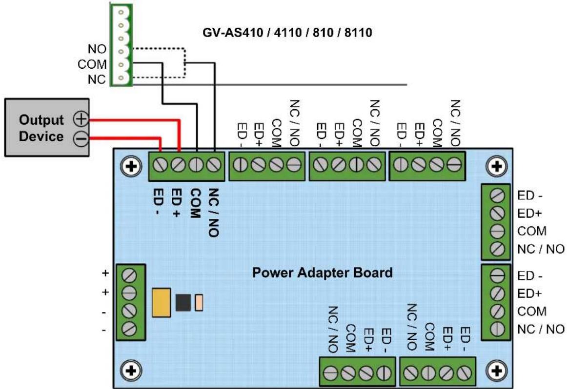
Figure 5-14
- When all connections are completed, connect the power supply to a 110-120V power source.
Note:
- The power supply of GV-AS410 / 4110 / 810 / 8110 Kit comes in US standard and EU standard. Make sure the device is connected with a voltage within its voltage range.
- You can place a backup battery in the supplied battery casing, and connect the backup battery to the GV-AS410 / 4110 / 810 / 8110 board. Refer to 5.2.4 Connecting Backup Battery for details.
6.4.4 GV-AS410 / 4110 / 810 / 8110 Kit Specifications
Power Adapter Board
| Output | DC Voltage Range | 12V |
| Rated Current | 0.9A | |
| Rated Power | 10.8 W | |
| Number of connectors | Input | 2 |
| Output | 8 | |
| Wire Size (AWG) | 12 - 22 | |
Power Supply
| Output | DC Voltage Range | 12V |
| Rated Current | 12.5A | |
| Current Range | 0~10A | |
| Rated Power | 150 W | |
| Input | US Standard | 110 – 120V, 50 Hz / 60 Hz |
| EU Standard | 200 – 240V, 50 Hz / 60 Hz |
GV-AS410 / 4110 / 810 / 8110 Kit
| Dimensions (L x W x H) | 420 x 300 x 110 mm / 16.5 x 11.8 x 4.33 in |
| Weight | 4.4 kg / 9.68 lb |
5.5 The Web Interface
You can install GV-AS410 / 4110 / 810 / 8110 on a network and configure GV-AS410 / 4110 / 810 / 8110 through its Web interface.
Refer to Chapter 7 Installing on a Network for detailed instructions on setting up a fixed or dynamic IP address to access GV-AS410 / 4110 / 810 / 8110.
Refer to Chapter 8 The Web Interface for details on the setup pages of the Web interface. Through the Web interface, you can configure general settings, input/output devices, associated doors/gates and connected readers.
5.6 GV-AS410 / 4110 / 810 / 8110 Specifications
| Software | ||
| Control Mode | GV-AS410 / 4110 GV-AS810 / 8110 | |
| One-Way Control 4 doors 8 doors | ||
| Two-Way Control | 4 doors by Wigand, RS-485 and Network | 4 doors by Wiegand8 doors by RS-485 or Network |
| Hardware | ||
| CPU 32-bit ARM7TDMI | ||
| Number of User Cards 40,000 cards | ||
| Event Buffer 1,000,000 events and log data | ||
| Power 100~250V AC, 50~60 Hz | ||
| RS-485 Interface | 1 RS-485 interface 2 RS-485 | interfaces |
| Up to 8 GV-Readers and GV-GF Fingerprint Readers | Up to 16 GV-Readers and GV-GF Fingerprint Readers | |
| Wiegand Interface | 8 Wiegand interfaces, 26 ~ 64 bit format | |
| 12V DC power supply, 200mA | ||
| TCP/IP Interface 1 TCP/IP interface for GeoVision network readers | ||
| Communication Protocol TCP/IP | ||
| Battery | GV-AS410 / 810: Built-in batteryGV-AS4110 / 8110: Replaceable button cell | |
| Input 16 inputs, dry contact, NO/NC | ||
| Output | 24 relay outputs (30V DC, 3A; 110 ~ 250V AC, 3A) | |
| Operating Temperature 0 ~ 65°C / 32 ~ 149°F | ||
| Operating Humidity 10% ~ 90% RH (non-condensing) | ||
| Dimensions (W X H X D) 210 x 187 x 40 mm / 8.27 x 7.36 x 1.57 in | ||
| Weight | 900 g / 2 lb | |
| Certification | CE, FCC, RoHS | |
All specifications are subject to change without notice.
- GV-EV48 Controller
6.1 Introduction
GV-EV48 is an elevator controller designed to control access of 1 elevator with a maximum of 48 floors. Up to 2 GV-Readers / GV-GF Fingerprint Readers can be connected to GV-EV48 using RS-485 connection and network connection. GV-EV48 can recognize identification cards and grant access to the authorized floors only.
6.1.1 Main Features
- Grant access to specific elevator floors using access cards, card's PIN code or fingerprints
• GV-EV48 – 24 Floors: Built-in 24 relay outputs to support up to 24 elevator floors
• GV-EV48 – 48 Floors: Built-in 48 relay outputs to support up to 48 elevator floors - Support up to 2 GV-Readers / GV-GF Fingerprint Readers through network connection and RS-485 connection
6.1.2 Packing List
• GV-EV48 – 24 Floors / 48 Floors
• Power Adaptor 12V DC / 3A
- Power Cord
- Battery Cable
- Micro SD Card 2 GB
- Software CD
6.1.3 GV-EV48 Board Layout
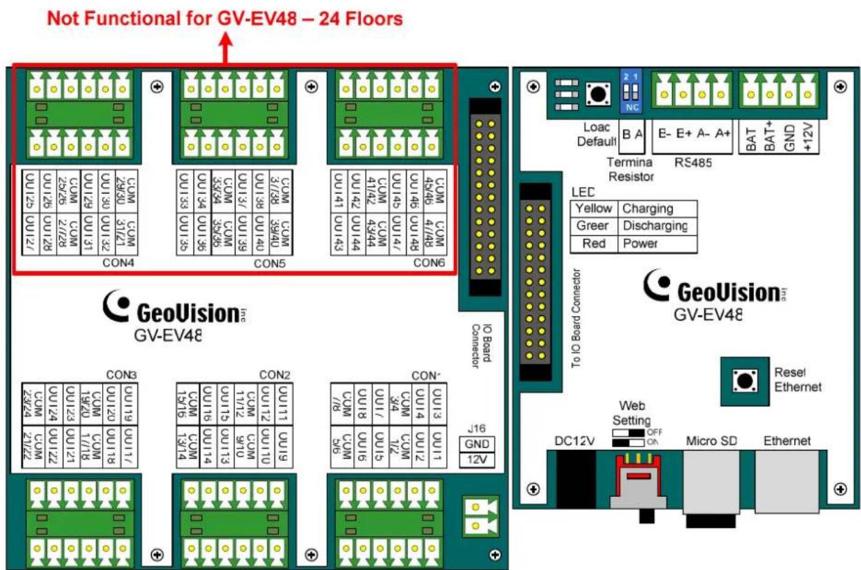
Figure 6-1
6.2 Installation
6.2.1 Connecting RS-485 Card Readers
With a single RS-485 cable, you can connect up to 2 GV-Readers and / or GV-GF Fingerprint Readers to the RS-485 interface on GV-EV48.
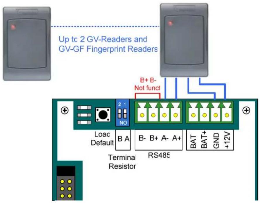
Figure 6-2
To connect to GV-CR420 or GV-GF1921 / 1922 through network connection, refer to 8.3.1 Extended Reader for details.
Note: When the RS-485 connection between GV-EV48 and the reader is over 600 meters, turn ON the RS485 A Terminal switch to avoid unstable signals. RS485_B Terminal Resister is not functional.
6.2.2 Connecting Output Relay
Up to 24 output relays can be connected to the GV-EV48-24 Floors to control up to 24 elevator floors. Up to 48 output relays can be connected to the GV-EV48-48 Floors to control up to 48 elevator floors. Each output relay is set to control access to a corresponding floor in the elevator.
To connect output relay:
Connect the output relay on the GV-EV48 to the corresponding floor on the elevator control panel. Next, connect the COM on the GV-EV48 to the COM on the elevator control panel.
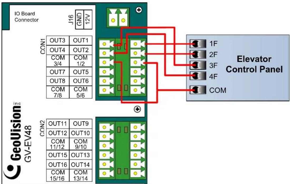
Figure 6-3
6.2.3 Connecting Backup Battery
Using the supplied battery cable, you can connect any battery of 12V 12Ah to GV-EV48 to provide backup power when the main power supply fails. When the main power supply is removed and the battery voltage level is above 10.2V, the Discharging LED will light and the battery will support normal operation of the GV-EV48.
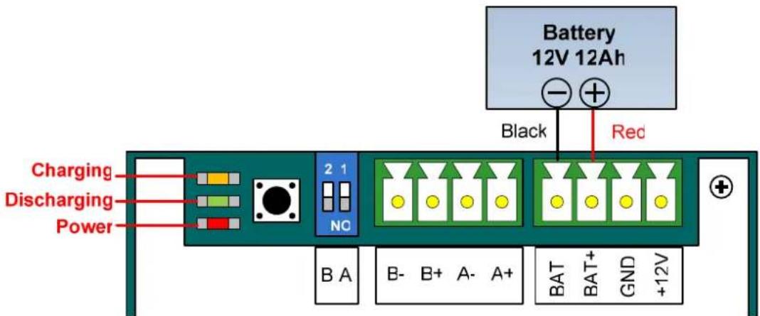
Figure 6-4
6.2.4 Connecting the Power
You can connect GV-EV48 to power directly using the supplied 12V DC adaptor. After power is connected, the power LED on GV-EV48 should glow.
Note: Power should only be applied to the unit when all connections are completed and tested.
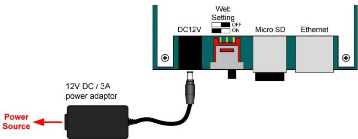
Figure 6-5
6.2.5 Connecting the PC
Connecting GV-EV48 to a computer allows you to access its Web interface and connects it to GV-ASManager if the computer is installed with GV-ASManager. The computer running GV-ASManager software can be used to monitor access information from GV-EV48. If connection with GV-ASManager is interrupted, GV-EV48 stores this information on the supplied micro SD card. The data stored will be sent to GV-ASManager when connection resumes.
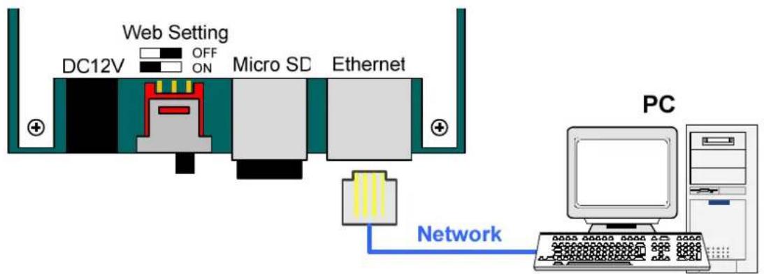
Figure 6-6
Note: GV-EV48 is only compatible with GV-ASManager V4.1 or later.
6.3 Other Settings
6.3.1 Web Setting Switch
When the Web Setting switch is set to the ON position, you can modify Advanced Settings and Extended Reader settings of GV-EV48 through its Web interfaces. When the switch is set to the OFF position, Advanced Settings and Extended Reader settings are not accessible. For details on Advanced Settings and Extended Reader settings, see 8.2 Advanced Settings and 8.3.1 Extended Reader.
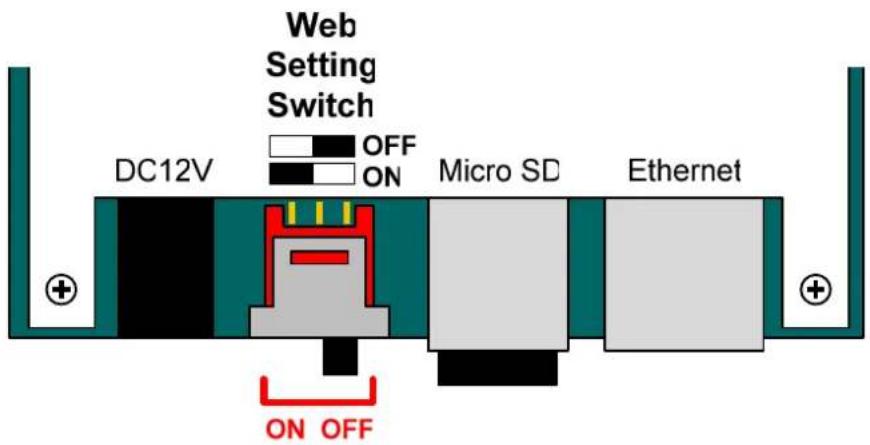
Figure 6-7
6.3.2 Resetting the GV-EV48
To reset GV-EV48, press the Reset button on the right side of GV-EV48 circuit board for three seconds.
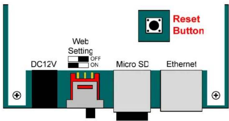
Figure 6-8
6.3.3 Restoring Factory Defaults
To restore GV-EV48 to factory default settings, press the Default button for 10 seconds.
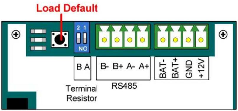
Figure 6-9
6.4 The Web Interface
You can install GV-EV48 on a network and configure GV-EV48 through its Web interface.
Refer to Chapter 7 Installing on a Network for detailed instructions on setting up a fixed or dynamic IP address to access GV-EV48.
Refer to Chapter 8 The Web Interface for details on the setup pages of the Web interface. Through the Web interface, you can configure general settings, specify which floors are restricted and establish connection with associated readers.
6.5 GV-EV48 Specifications
| CPU 32-bit ARM7TDMI | ||
| Number of User Cards 40,000 cards | ||
| Event Buffer 1,000,000 events and log data | ||
| Power 100~250V AC, 50~60 Hz | ||
| RS-485 Interface | 1 RS-485 interface only for GV-Readers and GV-GF Fingerprint Readers (max. 2 readers) | |
| TCP/IP Interface 1 TCP/IP interface for GeoVision network readers | ||
| Communication Protocol TCP/IP | ||
| Battery | Built-in battery | |
| Output | GV-EV48-24 Floors 24 | relay outputs (30V DC, 1A; 125V AC, 0.3A) |
| GV-EV48-48 Floors | 48 relay outputs (30V DC, 1A; 125V AC, 0.3A) | |
| Operating Temperature 0 ~ 65°C / 32 ~ 149°F | ||
| Operating Humidity 10% ~ 90% RH (non-condensing) | ||
| Dimensions (W X H X D) 210 x 170 x 55 mm / 8.27 x 6.69 x 2.17 in | ||
| Weight 610 g / 1.34 lb | ||
| Certification CE, FCC, RoHS | ||
All specifications are subject to change without notice.
7. Installing on a Network
You can install GV-AS1010 / 1110 / 210 / 2110 / 410 / 4110 / 810 / 8110 and GV-EV48 on a network and set up general settings, doors/gates/elevators, readers, and input/output devices through its Web interface. Through the network connection, you can also connect GV-AS / GV-EV Controller to GV-ASManager for more comprehensive management.
Note:
-
To access the Web interface of GV-AS100 / 110 / 120 and allow communication with GV-ASManager over the network, a GV-ASBox or GV-ASNet is required. Refer to Chapter 9 Optional Devices for more details.
-
The Web interface varies for different GV-AS Controller models.
The GV-AS / GV-EV Controller must first be assigned an IP address to make it accessible on the network.
-
Connect the network cable to the Ethernet port on GV-AS / GV-EV Controller.
-
Use a computer on the same LAN with the controller to assign an IP address.
- The default address is https://192.168.0.100
- The default Username and Password for login are admin
Note the computer used to set the IP address must be on the same network or subnet sequence assigned to the controller.
- GV-AS / GV-EV Controller is able to support two network environments: Fixed IP for a static IP address and DHCP for a dynamic IP address assigned by an ISP or DHCP server. Based on your network environment, refer to the next two sections for setup.
7.1 Fixed IP Connection
If your network environment supports a static IP address, the wiring is illustrated as below:
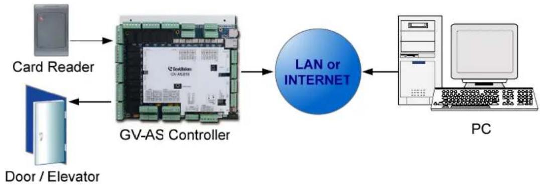
flowchart
graph LR
    A["Card Reader"] --> B["GV-AS Controller"]
    C["Door / Elevator"] --> B
    B --> D["LAN or INTERNET"]
    D --> E["PC"]
Figure 7-1
To assign the GV-AS / GV-EV Controller to a fixed IP:
- Open an Internet browser, and type the default IP address https://192.168.0.100. This dialog box appears.
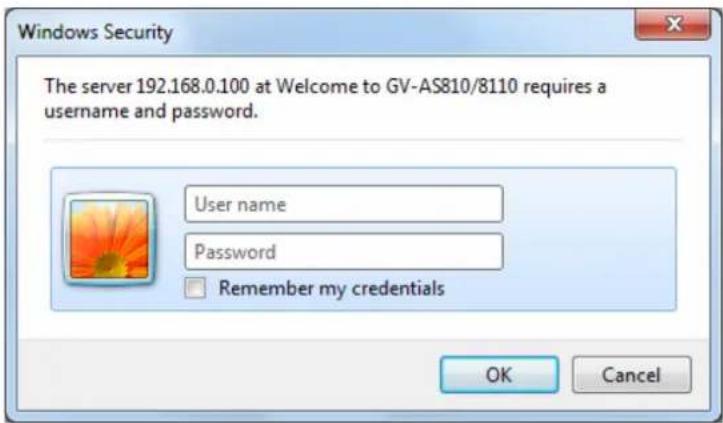
Figure 7-2
- Type the default value admin for both User name and Password, and click OK. This page appears.
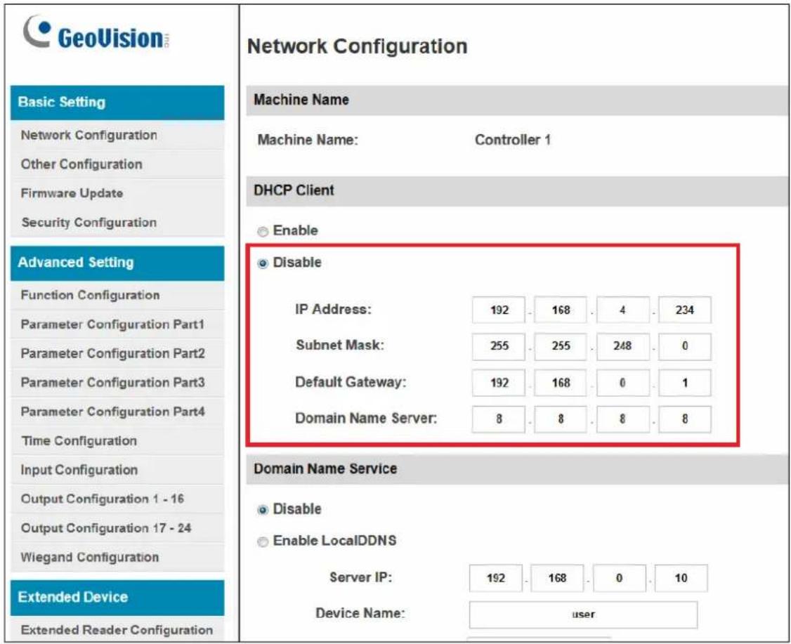
Figure 7-3
- In the DHCP Client section, click Disable. Type the static IP address information, including IP Address, Subnet Mask, Default Gateway and Domain Name Server.
- Click Submit. When the setting is complete, the Status field will indicate Register Success. Then GV-AS / GV-EV Controller can be accessed with this fixed IP address.
7.2 DHCP Connection
If your network environment is using the dynamic IP address from a DHCP server, use one of the following DDNS servers to map a dynamic IP address to a static domain name or device name:
- For LAN connection, GV LocalDDNS Server is provided.
- For Internet connection, two DDNS servers are supported: GeoVision DDNS Server and Dynamic Network Services Inc. (DynDNS).
7.2.1 Connection over LAN
GeoVision's GV LocalDDNS Server can map the changing IP address of your controller to a device name, allowing you to access the controller using the device name.
The Local DDNS Server can be installed in either GV-ASManager or a separate computer. The wiring of the LocalDDNS application is illustrated as below.
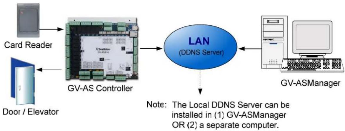
flowchart
graph LR
    A["Card Reader"] --> B["GV-AS Controller"]
    C["Door / Elevator"] --> B
    B --> D["LAN (DDNS Server)"]
    D --> E["Note: The Local DDNS Server can be installed in (1) GV-ASManager OR (2) a separate computer."]
    E --> F["GV-ASManager"]
Figure 7-4
Installing LocalDDNS Server
To install the LocalDDNS Server in a computer, download GV-Local DDNS Service from http://www.geovision.com.tw/english/5_8_AS.asp under the Supplemental Utilities section. Follow the on-screen instructions to install the application. After Installation, the program will be minimized to the system tray.
Configuring Controller on LAN
After running the LocalDDNS Server, configure the controller on LAN:
- Open an Internet browser, and type the default IP address https://192.168.0.100. The login dialog box appears.
- In the User Name and Password fields, type default value admin and admin respectively. Click OK. The Network Configuration page appears.
- Click Enable under DHCP Client, and select Enable Local DDNS.
- In the Server IP fields, type the IP address of the LocalDDNS Server.
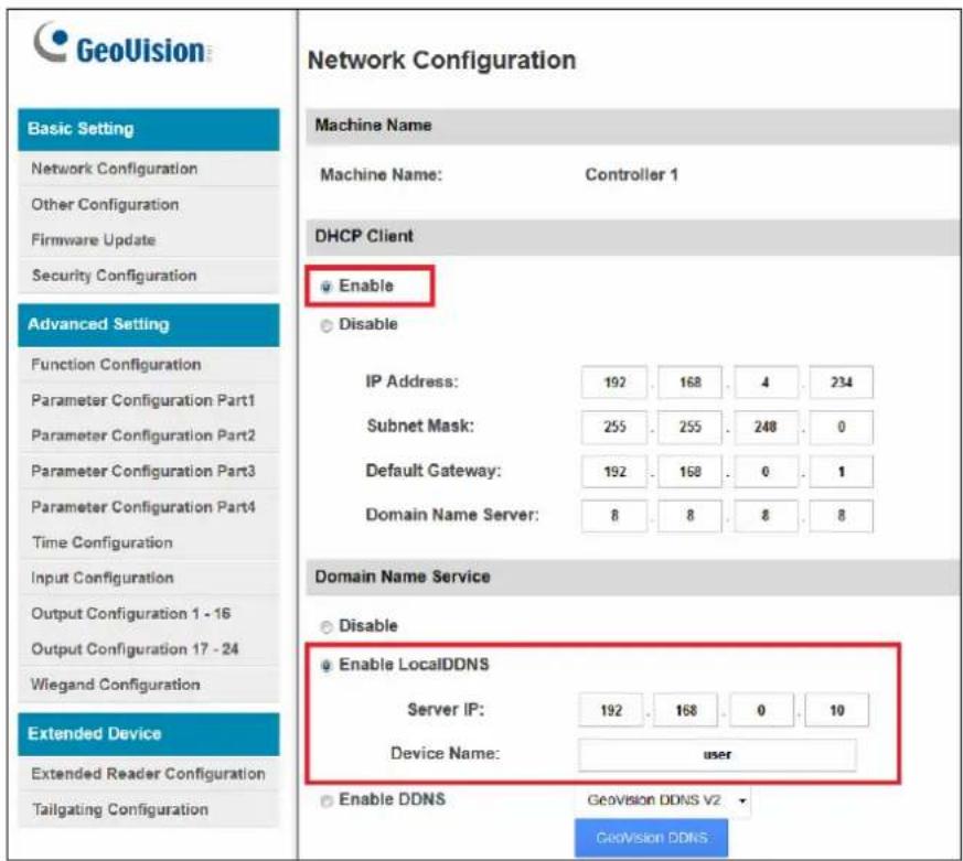
Figure 7-5
- In the Device Name field, keep the default setting or change it to match that of the GV-ASManager.
- Click Submit to send the information to the LocalDDNS Server. When the setting is complete, the Status field will indicate: Register Success. Then the controller can be accessed with the device name.
Note:
- The default value of Device Name is user. If more than one controller is connected to the GV-ASManager, assign each controller a different device name.
- To access the Device Name on GV-ASManager, open the Controller Setup dialog box, and select LocalDDNS in the Network drop-down list.
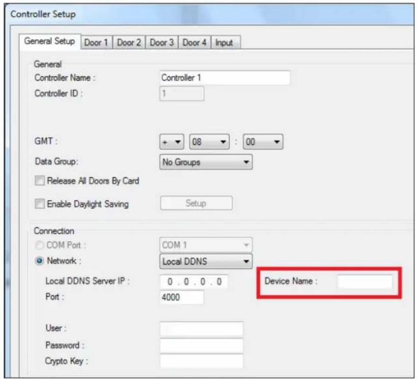
Figure 7-6
7.2.2 Connection over Internet
DDNS (Dynamic Domain Name System) provides another way of accessing GV-AS / GV-EV Controller when using a dynamic IP. DDNS assigns a domain name to the controller, so the GV-ASManager can always access the controller by using the domain name.
To enable the DDNS function, you should first apply for a domain name from the website of the DDNS service provider. There are 2 providers listed in the controller: GeoVision DDNS (V2) and DynDNS.org. To register at the GeoVision DDNS Server, see the following instructions. For details on DynDNS, please consult them at www.dyndns.org.
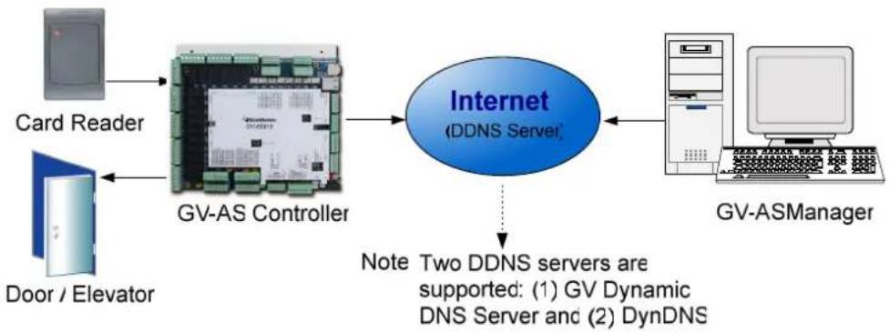
flowchart
graph LR
    A["Card Reader"] --> B["GV-AS Controller"]
    C["Door / Elevator"] --> B
    B --> D["Internet (DDNS Server)"]
    D --> E["Note: Two DDNS servers are supported: (1) GV Dynamic DNS Server and (2) DynDNS"]
    E --> F["GV-ASManager"]
Figure 7-7
Registering a DDNS Domain Name
Note that the interface may vary slightly for GeoVision DDNS Server V1 and V2. To obtain a domain name from the GeoVision DDNS Server:
- Click the GeoVision DDNS button on the Network Configuration page (Figure 7-5). Or open an Internet browser, and type the Web address http://ns.dipmap.com/register.aspx This page appears.
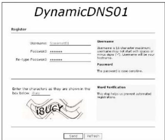
Figure 7-8
-
In the Username field, type a name. Username can be up to 16 characters with the choices of "a \~ z", "0 \~9", and "-". Note that space or "-" cannot be used as the first character.
-
In the Password filed, type a password. Passwords are case-sensitive and must be at least 6 characters. Type the password again in the Re-type Password field for confirmation.
-
In the Word Verification section, type the characters or numbers shown in the box. For example, type i8UCY in the required field. Word Verification is not case-sensitive.
-
Click the Send button. When the registration is complete, this page will appear. The Hostname is the domain name, consisting of the registered username and "dipmap.com", e.g. somerset01.dipmap.com.
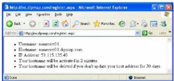
Figure 7-9
Note: The registered username will be invalid when it is not used for one month.
Configuring the GV-AS / GV-EV Controller on Internet
After acquiring a domain name from the DDNS Server, you need to configure the registered domain name on the controller to access the controller by the domain name on Internet.
- Open an Internet browser, and type the default IP address https://192.168.0.100. The login dialog box (Figure 7-2) appears.
- In the User Name and Password fields, type default value admin and admin respectively. Click OK. The Network Configuration page (Figure 7-10) appears.
- Click Enable, and select Send to DDNS.
- Type Host Name, User Name and Password that are registered on the DDNS Server. If you select GeoVision DDNS, the system will automatically bring up the Host Name.
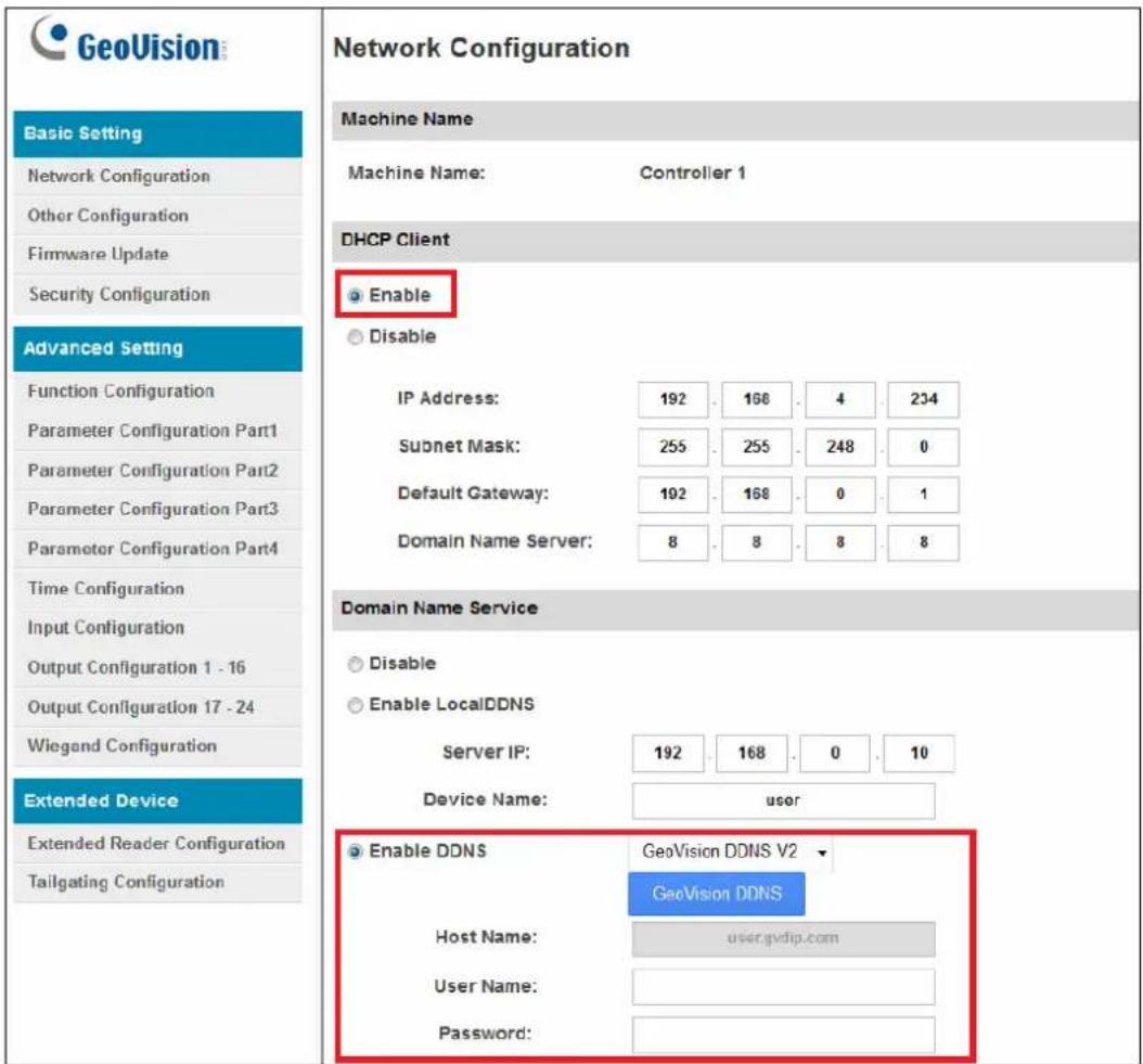
Figure 7-10
-
Click Submit. When the setting is complete, the Status field will indicate: Register Success. Then GV-AS / GV-EV Controller can be accessed with the domain name.
-
The Web Interface
After installing the GV-AS / GV-EV Controller on the network, you can configure the controller settings on the Web interface. The left menu of the Web interface is divided into three sections: Basic Setting, Advanced Setting and Extended Device. The options available vary among different controller models.
| Basic Setting |
| Network Configuration |
| Other Configuration |
| Firmware Update |
| Security Configuration |
| Advanced Setting |
| Function Configuration |
| Parameter Configuration Part1 |
| Parameter Configuration Part2 |
| Parameter Configuration Part3 |
| Parameter Configuration Part4 |
| Time Configuration |
| Input Configuration |
| Output Configuration 1 - 16 |
| Output Configuration 17 - 24 |
| Wiegand Configuration |
| Extended Device |
| Extended Reader Configuration |
| Tailgating Configuration |
Figure 8-1
8.1 Basic Settings
The Basic Settings section covers general system settings, firmware update and user account settings. For details on Network Setting, refer to Chapter 7 Installing on a Network.
8.1.1 System Setup
In the left menu, click Other Configuration. This page appears.
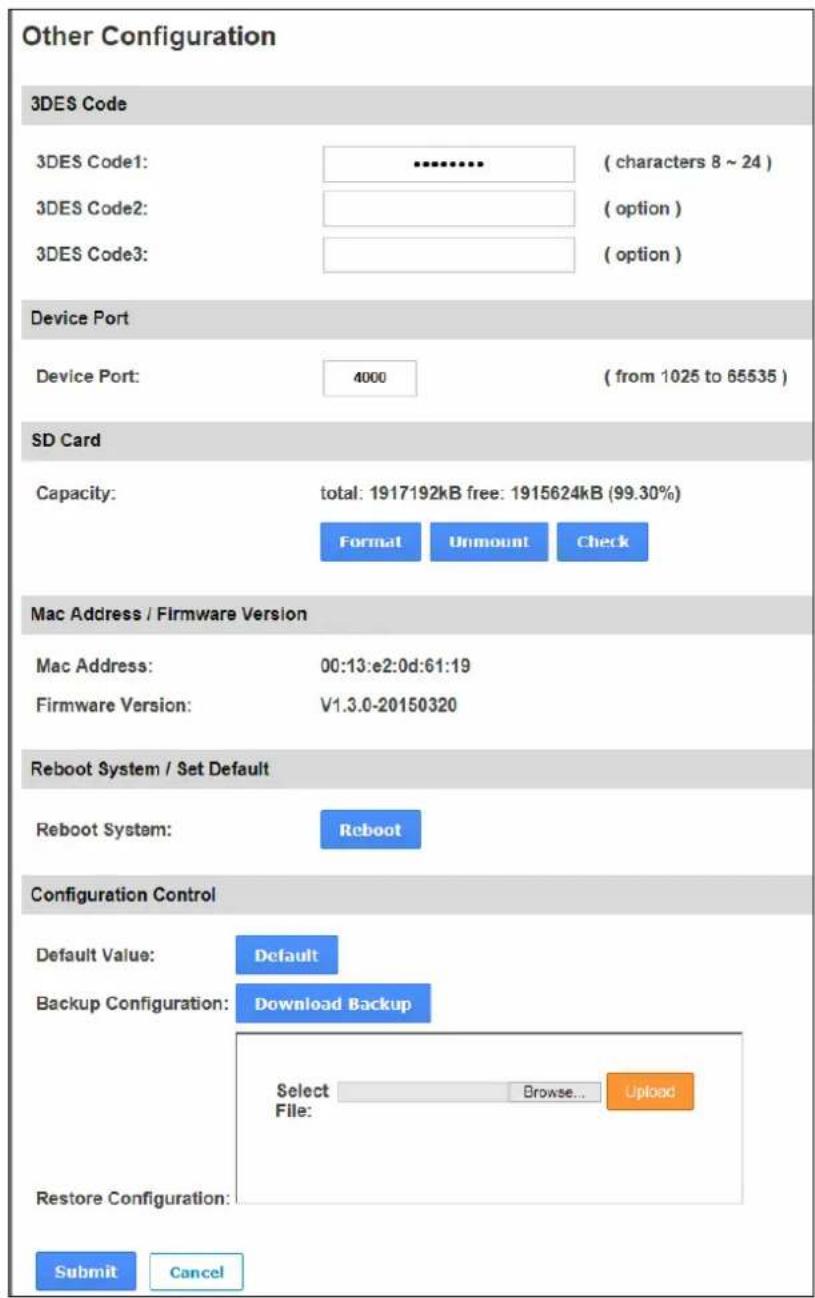
Figure 8-2
■ 3DES Code 1-3: Stands for Triple DES (Data Encryption Standard). Type up to three different keys for data encryption. The default 3DES Code1 is 12345678.
■ Device Port: Keeps the default value 4000. Or modify it to match that of GV-ASManager.
■ SD Card: Indicates capacity of the SD card inserted and allows you to format the SD card. To safely remove the inserted SD card, click Unmount. To check and repair the SD card, click Check. These functions are only available for GV-AS210 / 2110 / 410 / 4110 / 810 / 8110.
■ Mac Address: Indicates the MAC address of the network medium.
■ Firmware Version: Indicates the current firmware version of the controller.
■ Reboot System: Performs a warm boot of the controller. This operation will keep the current configuration.
■ Default Value: Resets all configuration parameters to their factory settings. This may take 5 seconds to complete.
■ Backup Configuration: To backup controller settings, click the Download Backup button. A .bin file will be exported. You can then import the file to other controllers to avoid setting each controller individually. Note that network settings such as IP address and hardware ID will NOT be included in the backed up file.
■ Restore Configuration: To import controller settings, click Browse to select the .bin file previously exported, and click the Upload button.
Note: The Backup Configuration and Restore Configuration functions are only available for the following controllers:
GV-AS210 / 2110 / 410 / 4110 / 810 / 8110 V1.23 or later
GV-AS1010 / 1110
● GV-EV48 V1.12 or later.
8.1.2 Upgrading Firmware
Follow the steps below to update the firmware of the controller.
- In the left menu, click Firmware Update. This page appears.
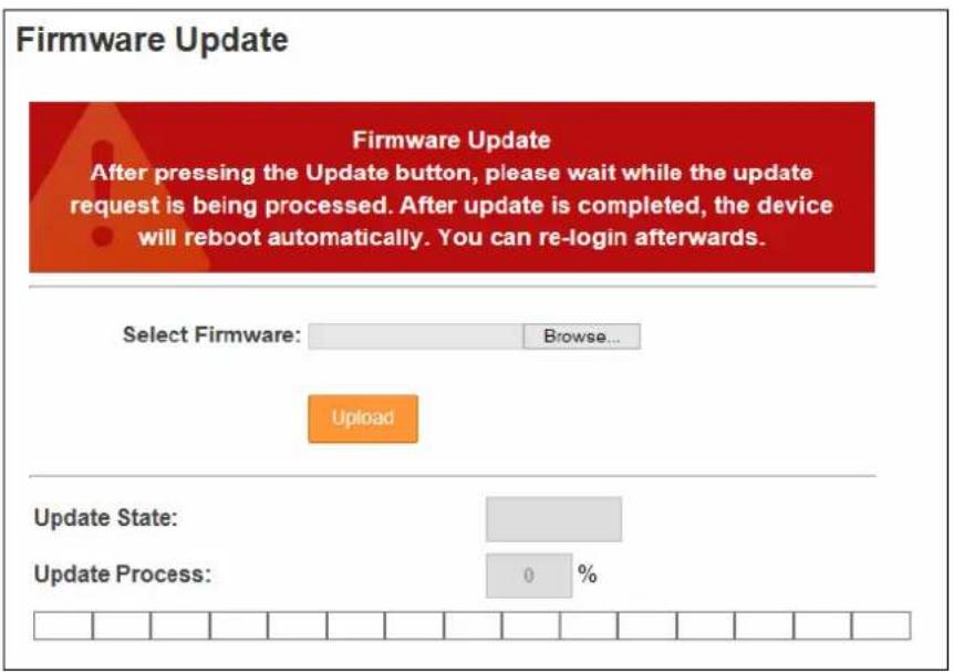
Figure 8-3
- Click the Browse... button to open the firmware file (*.bin)
- Click the Upload button. This update procedure may take 60 seconds to complete.
- When the Update is complete, a dialog box appears and asks you to reboot the system.
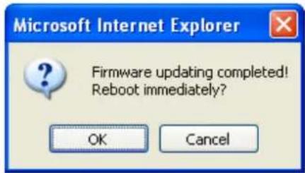
Figure 8-4
- Click OK. The controller starts the Reboot operation.
Note:
- Make sure the controller remains powered on during the firmware upgrade.
- It is required to reboot controller after firmware update. Without rebooting, the firmware update is not complete.
8.1.3 Changing Login ID and Password
To change the login ID and password:
- In the left menu, click Security Configuration.
- Modify the login name and password. The password is case sensitive and is limited to alphabets and numbers.
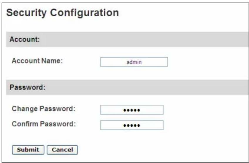
Figure 8-5
8.2 Advanced Settings
To configure the Advanced Setting on the Web interface, set the Web Setting switch on the GV-AS / GV-EV Controller to ON. See the Web Setting Switch section of each controller chapter.
Under Advanced Settings, you can configure door/Wiegand settings, turn on Alarms, set the device time and edit the input/output functions.
Changes in some of the Advanced Settings pages will affect the options available on other pages. Below is a diagram drawing the relationships between each Advanced Settings page.
The Relationship Diagram between each Advanced Setting Page
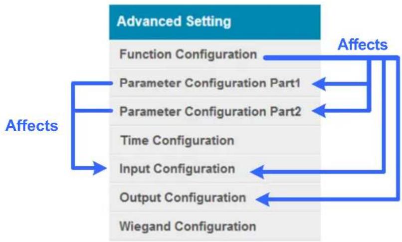
flowchart
graph TD
    A["Advanced Setting"] --> B["Function Configuration"]
    A --> C["Parameter Configuration Part1"]
    A --> D["Parameter Configuration Part2"]
    A --> E["Time Configuration"]
    A --> F["Input Configuration"]
    A --> G["Output Configuration"]
    A --> H["Wiegand Configuration"]
    I["Affects"] --> A
    style A fill:#4CAF50,stroke:#333
    style I fill:#2196F3,stroke:#333
Figure 8-6
Note:
- For GV-AS1010 and GV-AS1110, a Card Configuration page and a Card Information page are available.
- For GV-AS1010, a Function Key Configuration page is available.
For GV-EV48, the options available in Advanced Settings page are fixed. Only the following setting pages are available:
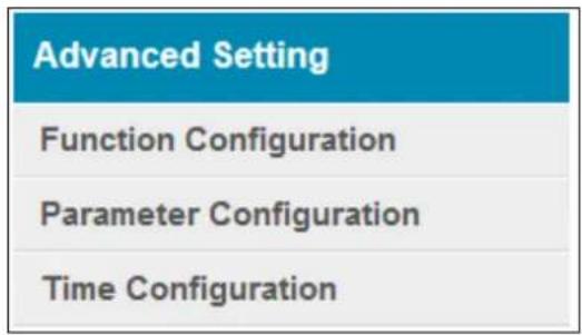
Figure 8-7
8.2.1 Function Configuration
In the left menu, click Function Configuration. The number of door/gate settings or elevator settings available varies among different models.
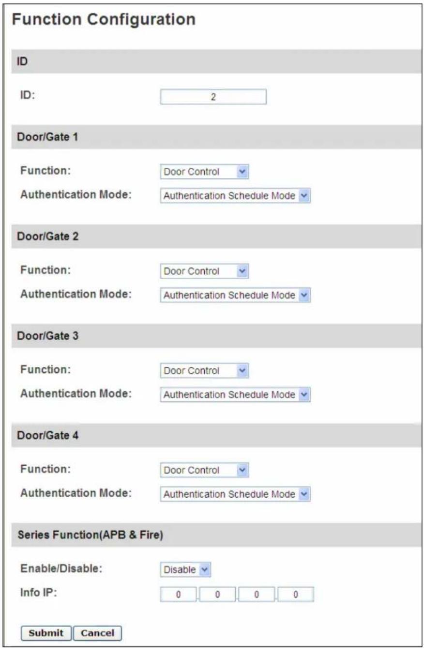
Figure 8-8
Note: For GV-EV48, only the ID and the Authentication Mode settings are available.
[ID]
Enter the ID number for the controller. This ID is used by GV-ASManager to differentiate among multiple units of controller. ID number can only be between 1 and 1000.
[Door/Gate #] [Elevator]
Select the function type and authentication mode for the use of the Doors/Gates. For GV-EV48, select an authentication mode to apply to all floors of the elevator.
■ Function: Select the function for the reader connected to the Door/Gate.
- Door Control: The reader is installed in a general door for access control.
Parking Control: The reader is installed in a parking place for access control. - Elevator Control: The reader is installed in an elevator for access control.
■ Authentication Mode: Select the authentication mode for the Doors/Gates or Elevator.
- Local Unlock Mode: Remains open. The held-open state cannot be cleared through GV-ASManager.
- Local Lock Mode: Remains locked. The locked state cannot be cleared through GV-ASManager.
- Fixed Card Mode: Grants access after the card is presented or the passcode is entered, and ignores the authentication schedule of GV-ASManager.
- Fixed Card + PIN Mode: Grants access after the user presents the card and enters the card's PIN code, and ignores the authentication schedule of GV-ASManager.
- Fixed Card/Common mode: Grants access after the user presents the card or enters the door's password, and ignores the authentication schedule of GV-ASManager.
- Authentication Schedule Mode: Follows the authentication schedule set on GV-ASManager.
- Local Lock Down: Locks down the door. This mode overrides the Authentication Schedule and the door can only be opened by presenting the assigned access card. This function is only available in GV-AS1010 / 1110.
[Series Function (APB & Fire)]
This option lets you set the Anti-Passback function and fire sensor function across multiple door controllers. The Anti-Passback means that a card used on an entry door cannot access the same entry door again unless it has been used on a corresponding exit door. For details on setup, see Chapter 6 Anti-Passback on GV-ASManager User's Manual.
For all zone fire sensor function, the fire sensors on all associated controllers will be triggered when the fire sensor on one door is triggered. For this function to work, you must set the Input Type to All Zone. For details, see the Input Setting section later in this chapter.
■ Enable/Disable: Enables or disables the Anti-Passback function and fire sensor function.
■ Info IP: Enter the IP address of the next corresponding controller.
Click Submit button to save the changes, or click Cancel button to return the changes to its previous state.
Note: The all zone fire sensor function is only supported by GV-AS210 / 2110 / 410 / 4110 / 810 / 8110 firmware V1.23 or later.
8.2.2 Parameter Configuration
In the left menu, click Parameter Configuration for GV-AS Controllers or click Elevator Parameter for GV-EV48.
IMPORTANT: Once connected to GV-AS / GV-EV Controller, GV-ASManager will load its parameters to the controller. That means some of the Parameter Settings you have configured here may be overwritten by GV-ASManager later.
8.2.2.A GV-AS1010 / 1110 / 210 / 2110 / 410 / 4110 / 810 / 8110
The contents of the Parameter Configuration page change based on your settings for Door/Gate # in the Function Configuration page (Figure 8-8). The number of door/gate settings available varies among different models.
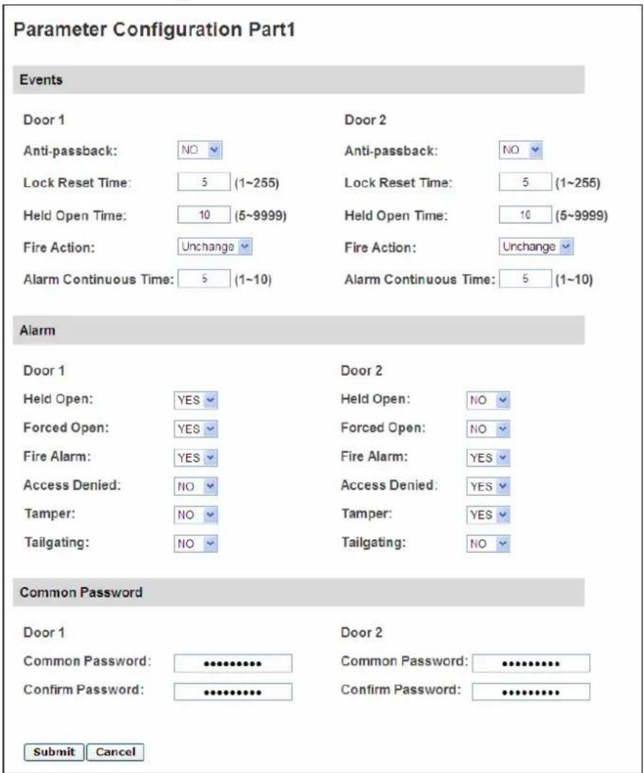
Figure 8-9
[Interlock] When the option is enabled, the two mentioned doors will be interlocked, allowing only one door to be opened at a time.
Note: The Interlock function is not available on the Web interface of GV-AS1010 / 1110 / 210 / 2110 / 410 / 4110 / 810 / 8110. To set up interlock function for these models, go to the Controller Setup page on GV-ASManager.
[Events]
Set the parameters for the events.
- When Door Control is selected in the Function Configuration page (Figure 8-8), these options become available:
| Option Description | |
| Anti-Passback Enables | or disables the Anti-Passback function. |
| Lock Reset Time | Sets the time (1 to 255 sec.) that a door remains open after which the door will automatically be locked. |
| Held Open Time | Sets the time (5 to 9999 sec.) that a door can be held open before an alarm is generated. |
| Fire Action | Locks or unlocks the door when a fire condition occurs. Otherwise, remains the door's current state by selecting Unchanged. |
| Alarm Continuous Time | Sets the time (1 to 10 sec.) that the alarm will continuously go off before it ends. |
- When Parking Control is selected in the Function Configuration page (Figure 8-8), these options become available:
| Option | Description |
| Anti-Passback | See the same option above. |
| Relay On Time | Sets the time (1 to 255 sec.) that a gate remains open after which the gate will automatically be closed. |
| Held Open Time | See the same option above. |
| Fire Action | |
| Alarm Continuous Time |
- When Elevator Control is selected in the Function Configuration page (Figure 8-8), these options become available:
| Option Description | |
| Relay on Time | See the same option above. |
| Fire Action | |
| Alarm Continuous Time | See the same option above. |
[Alarm]
Select Yes or No to enable or disable the alarm function. If you have defined the alarm conditions in the Input Configuration page (Figure 8-17), remember to activate the corresponding alarms here; otherwise, even though the alarm conditions are met, the expected alarm will not be triggered. The default settings for all the alarms are set to NO.
Note: The Tailgating alarm is currently not functional.
- When Door Control is selected in the Function Configuration page (Figure 8-8), these options become available:
| Option Description | |
| Held Open | This alarm activates whenever the door is held open over the set period of time. |
| Forced Open | This alarm activates whenever the door is opened by force. |
| Fire Alarm This alarm | activates whenever fire is detected. |
| Access Denied | This alarm activates whenever entry is denied due to using the wrong card or entering the wrong password. |
| Tamper | This alarm activates whenever the sensor for tampering alarm is triggered. For GV-AS210 / 2110 / 410 / 4110 / 810 / 8110, the tampering alarm sensor needs to be installed separately and the triggering conditions depend on the type of sensor installed, e.g. opening of the controller's cabinet. |
- When Parking Control is selected in the Function Configuration page (Figure 8-8), these options become available:
| Option Description | |
| Held Open | See the same option above. |
| Tamper | |
| Fire Alarm | |
| Access Denied |
- When Elevator Control is selected in the Function Configuration page (Figure 8-8), these options become available:
| Option Description | |
| Tamper | See the same option above. |
| Fire Alarm | |
| Access Denied |
[Common Password]
When Fixed Card/Common Mode is selected as Authentication Mode in the Function Configuration page (Figure 8-8), you can gain access by using a card or entering this Common Password (door's password).
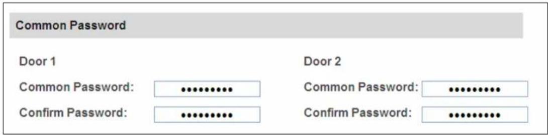
Figure 8-10
Click Submit button to save the changes, or click Cancel button to return the changes to its previous state.
8.2.2.B GV-EV48
The Parameter Configuration page allows you to specify which elevator floors are restricted.
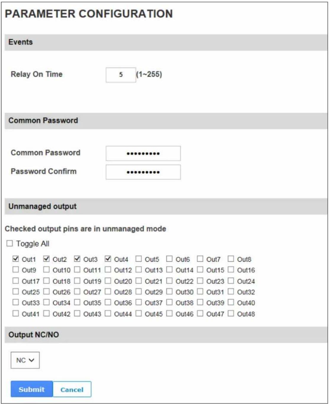
Figure 8-11
[Events]
- Relay On Time: Type a time period between 1-255 seconds. After access is granted by swiping a card or entering the password, the elevator button will remain accessible for the time period specified. After the specified time period, the elevator buttons for restricted floors will be locked again.
[Common Password]
When Fixed Card/Common Mode is selected as Authentication Mode in the Function Configuration page (Figure 8-8), you can gain access by using a card or entering this Common Password (elevator's password).
Note: Users typing the correct Common Password will be granted access to all floors enabled on GV-ASManager. To apply access control to specified floors, you will need to use the access card.
[Unmanaged Output]
Elevator floors of the selected output pins will be unrestricted and accessible without card or password. Authentication Mode configured in Function Configuration page will only be applied to output pins that are not selected. To select all output pins or to clear all selections, click Toggle All.
Note: For GV-EV48-24 Floors, output pins 25-48 are not functional.
Click Submit button to save the changes, or click Cancel button to return the changes to its previous state.
[Output NC/NO] Sets the output pins to NC or NO.
8.2.3 Card Configuration
In the left menu, click Card Configuration to set the built-in card reader of GV-AS1010 and GV-AS1110 to read UID (unique identification) or GID (GeoVision ID) on GV-AS ID F Card / Key Fob.
Note: The Card Configuration page is only available for GV-AS1010 and GV-AS1110.
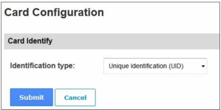
Figure 8-12
To use GeoVision Identification (GID), make sure there are two numbers on your GV-AS ID Cards / Key Fobs as shown below. If there is only one number on your GV-AS ID Cards / Key Fobs, GID is not supported and you must select Unique Identification (UID).
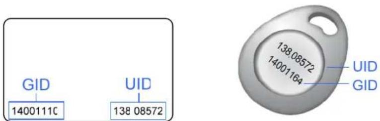
Figure 8-13
8.2.4 Card Information
In the left menu, click Card Information to see the cards added by GV-AS1010 and GV-AS1110 as a standalone unit. To delete all card information stored in GV-AS1010 / 1110, click the Clear Card Database button.
Note: The Card Information page is only available for GV-AS1010 and GV-AS1110.
Card Information
Clear Card Database
Card Database: 1-1 of 1
| Seq. | Card Number | Card Type |
| 0 | 005-34323 | Normal |

Per Page 1 / 1
Figure 8-14
8.2.5 Time Configuration
In the left menu, click Time Configuration to set up system time, local time and daylight saving time period.
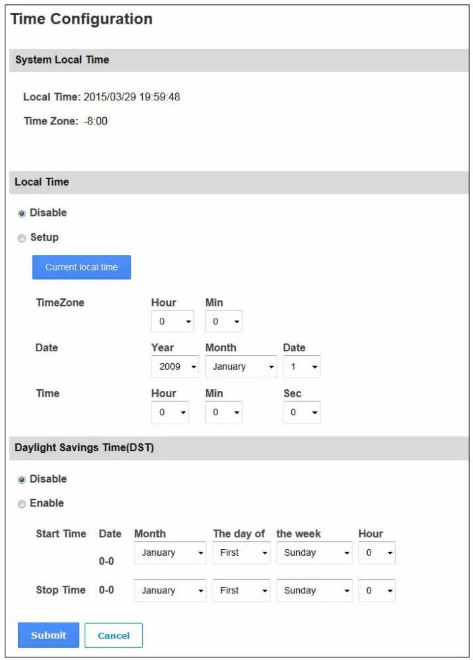
Figure 8-15
[System Local Time]
■ Local Time: Displays the current date and time of the controller.
■ Time Zone: Displays the current time zone of the controller.
[Local Time]
■ Disable: Disable the manual configuration of time and date.
- Setup: Enable the manual configuration of Time Zone, Date and Time for the controller. You can click the Current local time button to set synchronize the controller's date and time with the PC's current date and time.
[Daylight Savings Time (DST)]
■ Disable: Disable the manual configuration of DST.
■ Time Zone: Enable the manual configuration of DST by setting the Start Time and Stop Time for the DST period.
Click Submit button to save the changes, or click Cancel button to return the changes to its previous state.
8.2.6 Input Configuration
In the left menu, click Input Configuration to define the input devices connected to the GV-AS Controller. The number of input devices supported varies among different models.
Note: The Input Configuration page is not available for GV-EV48.
For GV-AS1010 and GV-AS1110, the Input Configuration page allows you to set the input sensors to NO or NC.
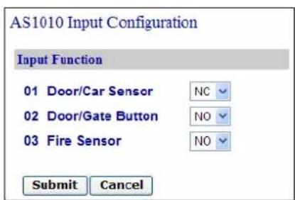
GV-AS1010
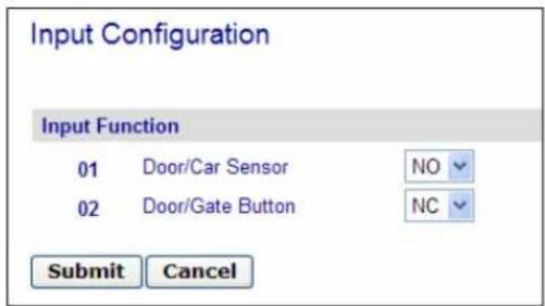
GV-AS1110
Figure 8-16
For other GV-AS Controller models, additional settings are available.
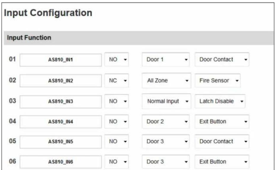
Figure 8-17
Note: The NO / NC option is only available for GV-AS1010 / 1110 / 210 / 2110 / 410 / 4110 / 810 / 8110. Input devices connected to GV-AS100 / 110 / 120 will use NO (Normally Open) circuit.
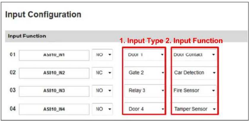
Figure 8-18
- Input Type: Configure the input type. Input Type defines the type of sensor that is connected to the input of GV-AS Controller. Options available for the input type change based on your Door/Gate # settings in the Function Configuration page (Figure 8-8).
- Input Function: Configure the input function. Options available for the input function change based on the settings of Input Type above.
Note: If you set the Input Type to All Zone, the Input Function will automatically be set to Fire Sensor. When triggered, fire sensors on all doors associated with that controller will be triggered.
| Input Type Input Function Description | ||
| Normal Input Enable LatchDisable Latch | The Normal Input is used for a normal detection mode in which the input is set to trigger an output. Instead of constant output alarm in N/O and N/C, the Enable Latch option provides a momentary alarm when triggered. | |
| Door # Fire ZoneTamper ZoneExit ButtonDoor Contact | Depending on the type of sensor and the location where it is installed, select the most suitable Input Function name to describe the sensor. When the sensor is activated, an alarm event may occur and it can also trigger alarms. For the type of alarm, see [Alarm], 8.2.2 Parameter Configuration.For example, when the Door Contact sensor detects unauthorized access, a “Force Open” type of event occurs and the event may trigger the “Force Open” alarm. | |
| Gate # Fire Sensor | Tamper ZoneExit ButtonCar Detection | See the “Door #” Input Type above.For example, when the Car Detection sensor detects any car driving by, a “Park Entry” or “Park Exit” type of event occurs and the parking gate will respond the event accordingly. |
| Relay # Fire Sensor | Tamper Zone | See the “Door #” Input Type above.For example, the Tamper Zone sensor is installed on GV-AS Controller. So whenever there is any attempt to open the GV-AS Controller’s cabinet, the “Tamper” type of event occurs and the event may trigger the “Tamper” alarm. |
Note: For alarm outputs, the corresponding alarms must be enabled (YES) in the Parameter Configuration page (Figure 8-9). If alarms are set to be disabled (NO), then the alarm function here will not work when triggered.
8.2.7 Output Configuration
In the left menu, click Output Configuration. The number of output devices supported varies among different models.
Note: The Output Configuration page is not available for GV-EV48, GV-AS1010 and GV-AS1110.
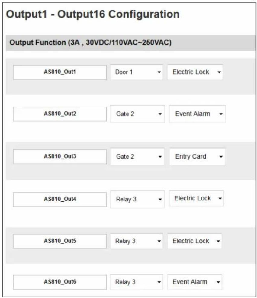
Figure 8-19
Here you can name and define each output device connected to the GV-AS Controller, such as locking devices and Exit Button. Select from the drop-down list to configure the Output Type. Depending on the chosen Output Type, either Output Function or Output Conditions will become available.
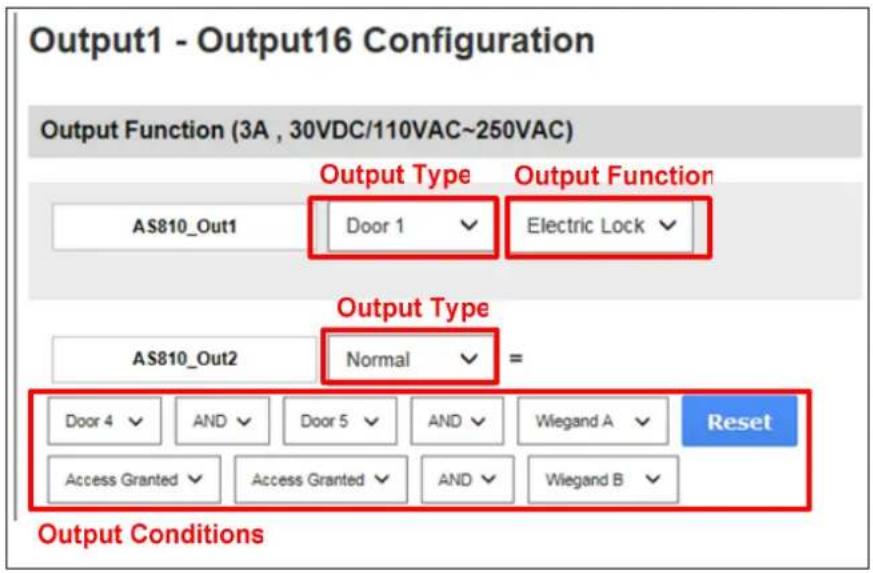
Figure 8-20
8.2.7.A Output Function Settings
This section explains the output functions available when Output Type is set to Door #, Gate # or Relay #.
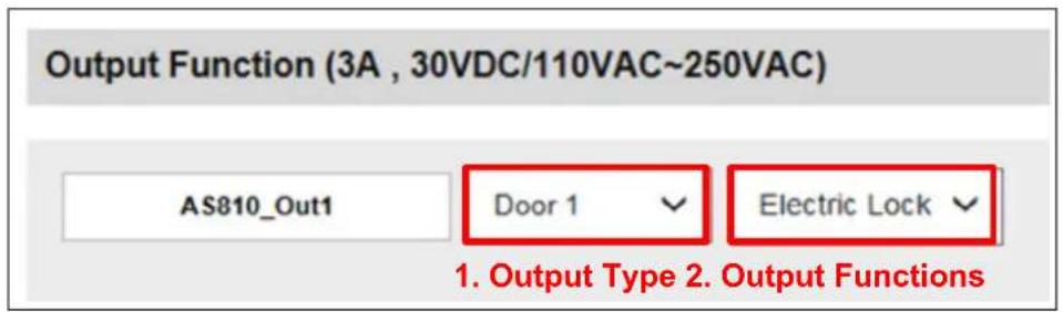
Figure 8-21
1. Output Type: Select the Door / Gate / Relay associated with this output. Options available for the output type change based on your settings of Door / Gate # in the Function Configuration page (Figure 8-8).
2. Output Function: Configure the output function. Options available for the output function change based on the Output Type selected above.
| Output Function | Description |
| Electric Lock Output is triggered when the correct card is presented to open the locking device. | |
| Event Alarm Output is triggered when the defined alarm events occur. | |
| Entry Card Output is triggered when the correct card is presented to enter the door / parking gate / elevator. | |
| Exit Card Output is triggered when the correct card is presented to exit the door / parking gate / elevator. | |
| Unlock Alarm Output is triggered when the door is unlocked or when the parking gate is open. This option is not available when Relay is selected as Output Type. | |
8.2.7.B Output Condition Settings
This section explains the output functions available when Output Type is set to Normal, Toggle or Pulse.
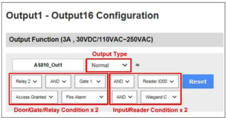
Figure 8-22
There can be a maximum of 4 conditions that can be set up to trigger an output. 2 conditions are Door/Gate/Relay conditions and 2 conditions are Input/Reader conditions. Each condition is related to each other through AND/OR. AND means that all conditions with AND must be triggered before the output is triggered. OR means that only 1 of the condition with OR is needed to be triggered before the output is triggered. It is also valid to have certain conditions as AND and certain conditions as OR.
For Pulse output type, the output is triggered for the amount of time set in the Sec field (seconds).
In the Output Condition settings, these Output Type and Output Condition become available:
| Output Condition Output Type | ||||
| Door # | Gate # | Relay # | Input/Reader | |
| Normal Toggle Pulse | Access Granted | Access Granted Access Granted | Access Granted | Select None to disable the condition, or select an Input, Wiegand, or Reader to trigger the output. |
| Access Denied | Access Denied Access Denied | |||
| Fire Alarm Fire Alarm | Fire Alarm | |||
| Tamper Tamper | Tamper | |||
| Duress Event Duress Event Duress | Event | |||
| Held Open Held Open | ||||
| Forced Open Forced Open | ||||
| Exit Button Exit Button | ||||
| Door Contact Car Detection | ||||
Click Reset button to return the Normal, Toggle or Pulse triggered state to be normal.
Note: The Reset button is more commonly used for the Toggle output because once triggered, the output will go on forever. A Reset button is needed to turn it off.
Click Submit button to save the changes, or click Cancel button to return the changes to its previous state.
8.2.8 Wiegand Configuration
In the left menu, click Wiegand Configuration to define the connected Wiegand readers. The number of Wiegand devices supported varies among different models. For GV-AS2110 / 4110 / 8110, connection status is available and indicated by green or red.
Note: The Wiegand Configuration page is not available for GV-AS1010 / 1110 and GV-EV48.
Use the drop-down list to select the location where the Wiegand reader is installed.
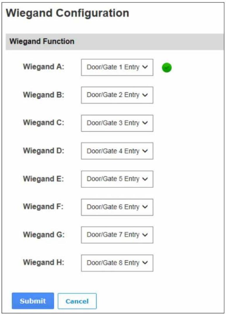
Figure 8-23
8.2.9 Function Key Configuration
In the left menu, click Function Key Configuration to define the function keys on GV-AS1010.
Note: The Function Key Configuration page is only available for GV-AS1010.
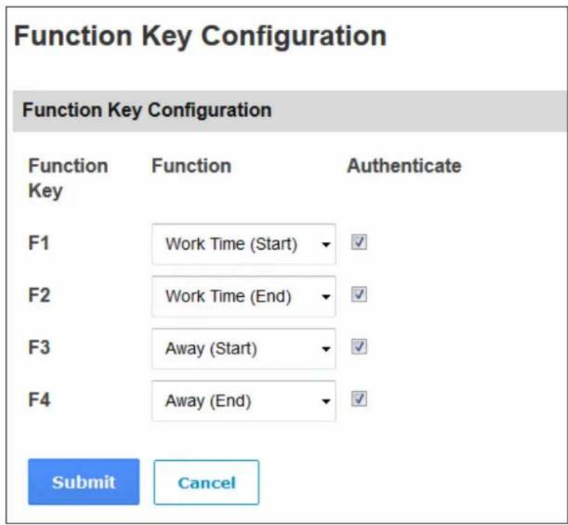
Figure 8-24
Set the function keys to be the start or end of Work Time, Away, Overtime or Break Time. When employees present their access card to GV-AS1010, they can press the function keys to indicate the card swipe as the start or end of Work Time, Away, Overtime or Break Time. If you select Authenticate, the door or elevator call button will be unlock when the user present the access card after pressing a function key.
The attendance record can be looked up in GV-TAWeb. Refer to Chapter 11 GV-TAWeb for Workforce Schedule and Payroll in GV-ASManager User's Manual for details.
8.3 Extended Device
You can define the GV-Readers and GV-GF Fingerprint Readers connected to GV-AS / GV-EV Controller through RS-485 or network connection.
Note: The Tailgating Setting page is currently not functional.
8.3.1 Extended Reader
In the left menu, click Extended Reader Configuration. This page appears.
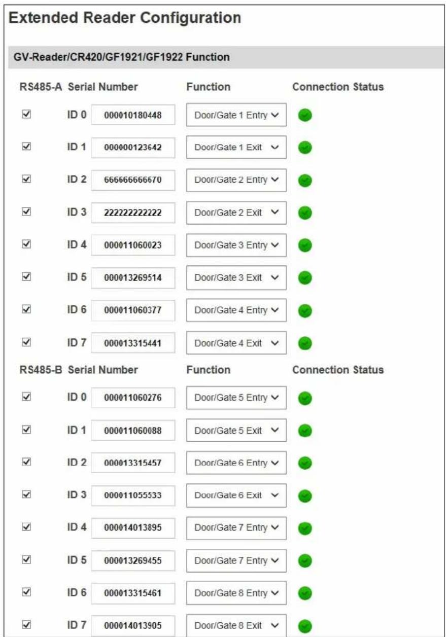
other
Extended Reader Configuration | RS485-A | Serial Number | Function | Connection Status | |---|---|---|---| | ✓ | ID 0 | 000010180448 | ✓ | | ✓ | ID 1 | 000000123642 | ✓ | | ✓ | ID 2 | 66666666670 | ✓ | | ✓ | ID 3 | 22222222222 | ✓ | | ✓ | ID 4 | 000011060023 | ✓ | | ✓ | ID 5 | 000013269514 | ✓ | | ✓ | ID 6 | 000011060377 | ✓ | | ✓ | ID 7 | 000013315441 | ✓ | RS485-B | Serial Number | Function | Connection Status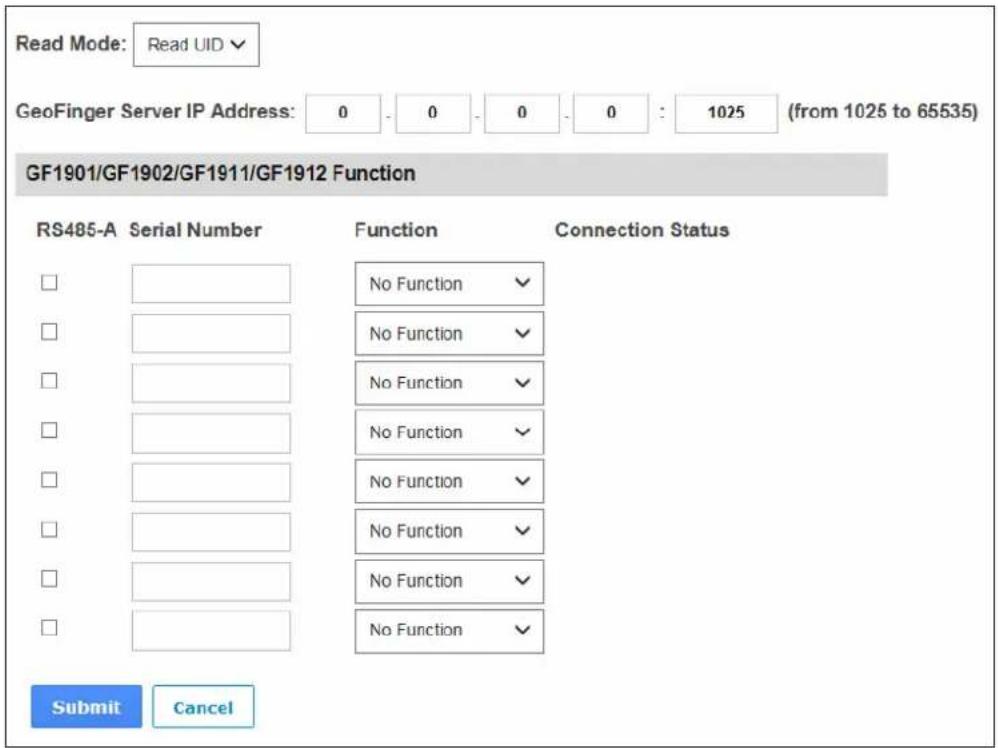
Figure 8-25
[GV-Reader / CR420 / GF1921 / 1922 Function] Define the readers connected to the controller, and then use the Function drop-down list to select the door associated with the reader.
- GV-RK1352 / R1352 / DFR1352: Select the RS-485 checkbox and type the Serial Number of the reader. Note that the ID number located next to the serial number field need to match the reader's ID number defined through the GV-RK1352 Config AP.
- GV-Reader 1251 / Reader 1352 V2: Select the RS-485 checkbox and leave the serial number field blank. Note that the ID number located next to the serial number field need to match the reader's ID number defined by the dip switches on the reader.
- GV-GF1921 / GF1922: Type the MAC address of the fingerprint reader and do not select the RS-485 checkbox.
- GV-CR420: Select the RS-485 checkbox only if the GV-CR420 is connected to the controller through RS-485 connection. If the reader is using network connection, do not check the RS485 box. Type the MAC address of GV-CR420 if you using the latest GV-CR420 firmware. Refer to the note below if you are using firmware V1.0.
[Read Mode] Select Read UID or Read GID to set the connected GV-R1352 / RK1352 / DFR1352 (Rev. B) to read UID (unique identifier) or GID (GeoVision ID) on the card / key fob. If you select Read GID, make sure there are two numbers on your GV-AS ID Cards / Key Fobs as shown below. If there is only one number on your GV-AS ID Cards / Key Fobs, GID is not supported and you must select Unique Identification (UID).
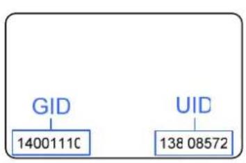
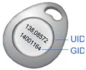
Figure 8-26
Note: GID is only supported by GV-R1352 / RK1352 / DFR1352 (Rev. B) with firmware V1.2 or later.
[GeoFinger Server IP Address] To allow GV-ASManager to receive data from the GV-GF1921 / 1922 defined on this page during remote fingerprint enrollment, type the IP address and port of the GV-ASManager's GeoFinger Server. You can also complete this step on the Web interface of each GV-GF1921 / 1922 individually as shown below.
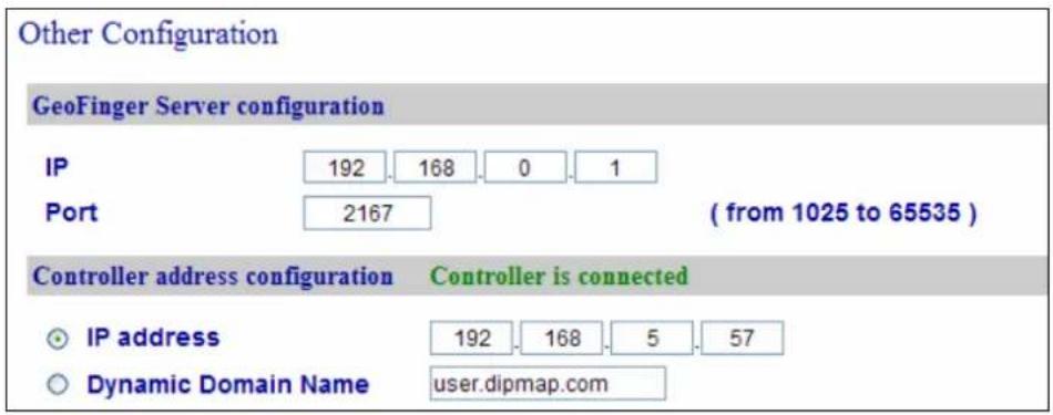
Figure 8-27
Note:
-
To allow network connection, you must also enable network connection to the controller on the Web interface of the GV-CR420 or GV-GF1921 / 1922.
-
Refer to the table for connecting GV-CR420 and GV-AS Controllers through network.
| CR420 V1.0 CR420 V1.01 | ||
| GV-AS210 / 410 / 810 V1.1 or laterGV-EV48GV-AS1010 / 1110 / 2110 / 4110 / 8110 | Not Supported MAC Address | |
| GV-AS210 / 810 V1.0GV-AS100 / 110 / 120 with ASBox / ASNet | Barcode | Not Supported |
[GF1901 / GF1902 / GF1911 / GF1912 Function] Define the GV-GF1901 / 1902 / 1911 / 1912 connected to the controller.
- GV-GF1901 / GF1902: Select the RS-485 checkbox and type the XID Number located on the back of the reader.
- GV-GF1911 / GF1912: Select the RS-485 checkbox only if the GV-GF1911 / 1912 is connected to the controller through RS-485 connection. If the reader is using network connection, do not check the RS485 box. Type the XID Number located on the back of the reader.
Click Submit. If the reader is detected, the Connection Status field will be green.
9. Optional Devices
9.1 Optional GV-ASBox
The optional GV-ASBox is the I/O and network expansion module for GV-AS100, GV-AS110 and GV-AS120. With the GV-ASBox, additional network connectivity, 8 inputs, 8 outputs and 1 Wiegand reader can be added to GV-AS100, GV-AS110 or GV-AS120.
9.1.1 Main Features
- Add TCP/IP networking capability to GV-AS100 / 110 / 120
- Extend GV-AS100 / 110 / 120 from 1-door to 2-door controller
• Support 1 Wiegand reader of 26 to 64 bits
• Support 8 digital inputs and 8 relay outputs - 4 special outputs for lighting control and energy saving
- Access GV-AS100 / 110 / 120's features through Web-based interfaces
- Route digital I/O controls from GV-AS100 / 110 / 120 to avoid tamper and enhance security level
- Support 4 units of GV-Readers and GV-GF Fingerprint Readers
9.1.2 Packing List
- GV-ASBox
• Power Adaptor 12V DC - Power Cord
- Battery power cable
9.1.3 GV-ASBox Board Layout
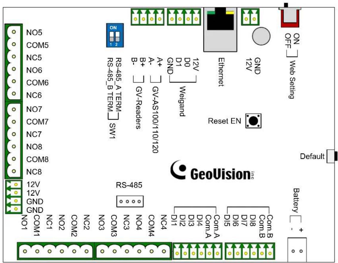
Figure 9-1
9.1.4 Installation
This section describes how to connect other devices to GV-ASBox.
9.1.4.A Connecting GV-AS100 / 110 / 120
The table and figure below show the pin assignments of related connectors on GV-ASBox for connection to GV-AS100, GV-AS110 and GV-AS120.
| A+ | GV-AS100/110/120 |
| A- | |
| B+ | GV-Readers |
| B- | |
| RS-485_A TERM | |
| RS-485_B TERM | |
Figure 9-2
| Pin | Function | Pin | Function | Pin | Function |
| 12V | 12V Power Supply to GV-AS100/110/120 | A+ | GV-AS100/110/120 Connection | B+ | GV-Readers Connection |
| GND | GND for Power Supply to GV-AS100/110/120 | A- | GV-AS100/110/120 Connection | B- | GV-Readers Connection |
Note:
- By default, RS-485_A Term and RS-485_B Term are set to OFF.
- When the distance between the GV-ASBox and the GV-AS100 / 110 / 120 is over 600 meters, RS-485_A Term must be switched to ON. When the distance between the GV-ASBox and the GV-Readers is over 600 meters, RS-485_B Term must be switched to ON.
9.1.4.B Connecting a Wiegand Reader
GV-ASBox provides one Wiegand input for connection of the Wiegand-compatible reader ranging from 26 to 64 bits. The connected Wiegand reader can either work with GV-AS100/GV-AS110/GV-AS120 to carry out entry and exit applications on a single door, or be installed on another door for the two-door application.
The table below shows the pin assignments of the Wiegand input on GV-ASBox. Please consult the documentation of your Wiegand reader for wiring.
| Pin Function |
| GND GND for the Power Supply |
| D0 Wiegand Data 0 |
| D1 Wiegand Data 1 |
| 12V 12V Power Supply |
To define the reader, you need to use the GV-AS100/GV-AS110/GV-AS120 Web interface. See 9.3.2.B Parameter Setting.
9.1.4.C Connecting GV-Readers and GV-GF Fingerprint Readers
You can connect up to 4 units of GV-Readers and GV-GF Fingerprint Readers to GV-ASBox. Multiple GV-Readers and GV-GF Fingerprint Readers can be connected with a single RS-485 cable to separate RS-485 interfaces on GV-ASBox.
Since Wiegand communication distance is shorter than RS-485's, you can choose GV-Reader and GV-GF Fingerprint Reader supporting RS-485 communication to add another door control and meet the need of long-distance installation.
Use the RS-485 B+ B- to connect to GV-Readers and use the RS-485 interface to connect GV-GF Fingerprint Readers. Refer to the figure below to see where the RS-485 interfaces are located. When multiple readers are connected together, an extra power supply to each unit is required. Use the auxiliary power output of 12V and GND on GV-ASBox to power on each unit.
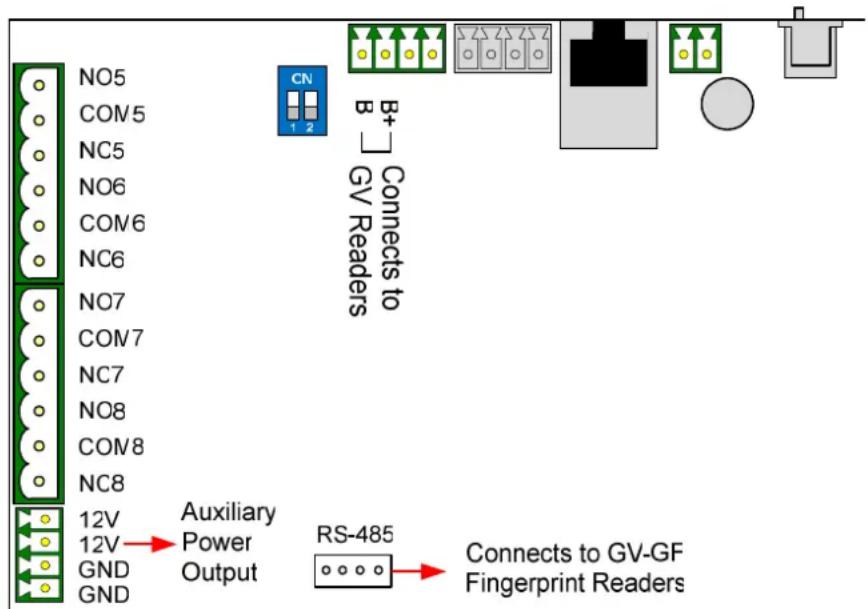
Figure 9-3
To define each GV-Reader and GV-GF Fingerprint Reader, you need to use the GV-AS100/GV-AS110/GV-AS120 Web interface. See 9.3.2.G Extended Reader Setting.
Note: The RS-485 connector on GV-ASBox is only designed for the connection of GV-Readers and GV-GF Fingerprint Readers.
9.1.4.D Connecting Input Devices
GV-ASBox provides 8 inputs (DI1 to DI8). All inputs are dry contact and can be configured as normally open (NO) or normally closed (NC) through the Web interface. The default value is NO.
The figure below shows the pin assignments of input connectors on GV-ASBox. The 8 inputs are divided into two terminals. Terminal A consists of DI1 to DI4, and terminal B includes DI5 to DI8. Every terminal has two COM (Common) points; connect the Common wire to any of the two COM points on the related terminal.
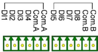
flowchart
graph TD
    subgraph LeftStructure
        A["Com.A"] --> B["DI1"]
        A --> C["DI2"]
        A --> D["DI3"]
        A --> E["DI4"]
        A --> F["Com.A"]
    end
    subgraph RightStructure
        G["Com.B"] --> H["DI5"]
        G --> I["DI6"]
        G --> J["DI7"]
        G --> K["DI8"]
        G --> L["Com.B"]
    end
    style LeftStructure fill:#f9f,stroke:#333
    style RightStructure fill:#bbf,stroke:#333
Figure 9-4
9.1.4.E Connecting Output Devices
GV-ASBox provides 8 outputs and 2 auxiliary power outputs of 12V DC. The outputs are divided into two groups, outputs 1 \~ 4 and outputs 5 \~ 8. Before connecting, make sure if your output device meets any of the two different absolute maximum ratings listed below.
Additionally, you can wire the light switch to the outputs 5 \~ 8 for lighting control. When the access is granted, the light is turned on; when the exit is granted, the light is turned off. See To combine door access with relay activation below.
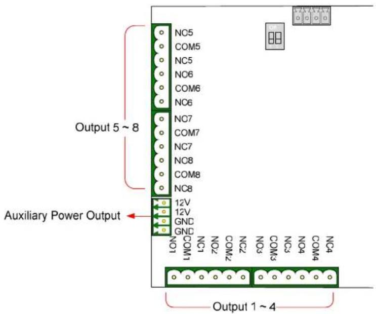
Figure 9-5
Outputs 1-4: Absolute Maximum Ratings
| Breakdown Voltage | 277V AC, 30V DC |
| Continuous Load Current | 5A (NO), 3A (NC) |
| Note: Absolute Maximum Ratings are those values beyond which damage to GV-ASBox circuit board may occur. Continuous operation of GV-ASBox at the absolute rating level may affect GV-ASBox reliability. | |
Outputs 5-8: Absolute Maximum Ratings
| Breakdown Voltage | 240V AC, 30V DC |
| Continuous Load Current | 16A (NO), 8A (NC) |
| Note: Absolute Maximum Ratings are those values beyond which damage to GV-ASBox circuit board may occur. Continuous operation of GV-ASBox at the absolute rating level may affect GV-ASBox reliability. | |
To connect an output device:
GV-ASBox provides two auxiliary power outputs of 12V DC at a maximum current of 1A. If your output device requires higher current, you must have the power supplied from an external power supply. Connect the (+) point on the output device to COM on GV-ASBox, connect the (-) points on the output device and the external power supply together, and connect the (+) point on the external power supply to the NO or NC of GV-ASBox based on the state of the output device.
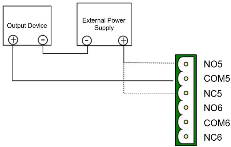
Figure 9-6
To combine door access with relay activation:
You can combine door access with relay activation for light control, machine control, etc., so that these will only be active when access is granted. For example, the light is turned on when a user is granted access to a room; the light is turned off when the user exits from the room. For this function, wire the relay switch to output 5 \~ 8.
9.1.4.F Connecting Backup Battery
You can connect any battery of 12V 12Ah to GV-ASBox to provide backup power when the main power supply fails. When the main power supply is removed and the battery voltage level is above 10.2V, the battery will support normal operation of the GV-ASBox.
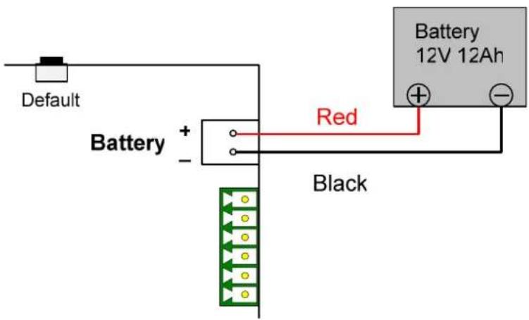
Figure 9-7
9.1.4.G Other Settings
The figure below shows the location of the Web Setting Switch, Reset Button and Default Button.
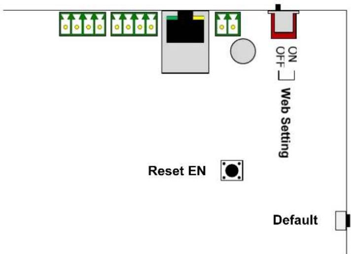
Figure 9-8
9.1.4.G.a Web Setting Switch
When the Web Setting switch is set to ON, you can modify Advanced Settings of GV-AS100, GV-AS110 and GV-AS120 through the Web interface. When the switch is set to OFF, Advanced Settings are not accessible. For details on Advanced Settings, see 9.3.2 Advanced Settings.
9.1.4.G.b Resetting the GV-ASBox
To reset GV-ASBox, press the Reset EN button on GV-ASBox for 3 seconds.
9.1.4.G.c Restoring Factory Defaults
To restore factory default values, press the Default button on GV-ASBox for 3 seconds. After this it may take up to 3 minutes to restore GV-ASBox to default values.
9.1.5 GV-ASBox Specifications
| CPU 32-bit ARM7TDMI Microprocessor | ||
| Power 100 ~ 240V AC, 50 ~ 60 Hz | ||
| Battery | 12V, 5Ah | |
| RS-485 Interface | 2 separate interfaces for GV-Readers and GV-GF Fingerprint Readers (Max. 4 readers) | |
| Wiegand Interface | 1 Wiegand interface, 26 ~ 64 bit format | |
| 12V DC Power Supply, 200mA | ||
| Communication Protocol | GV-AS100/110/120 | RS-485 |
| GV-ASManager TCP/IP (10/100 Mbps Ethernet) | ||
| Digital I/O | Input 8 inputs, dry contact, NO / NC | |
| Output 8 outputs | ||
| Operating Temperature 0 ~ 65°C / 32 ~ | 149°F | |
| Operating Humidity 10% ~ 90% RH (non-condensing) | ||
| Board Dimensions (W X H X D) | 214 x 206 x 48.5 mm / 8.43 x 8.11 x 1.91 in | |
| Weight 850 g / 1.83 lb | ||
| Certification CE, FCC, RoHS | ||
All specifications are subject to change without notice.
9.2 Optional GV-ASNet
The optional GV-ASNet is the network expansion module for GV-AS100, GV-AS110 and GV-AS120. With the GV-ASNet, GV-AS100 / 110 / 120 can be connected to the GV-ASManager and you can access the Web interface of GV-AS100 / 110 / 120.
9.2.1 Main Features
- Add TCP/IP networking capability to GV-AS100 / 110 / 120
- Access GV-AS100 / 110 / 120's features through Web-based interfaces
- Support 2 units of GV-Readers and GV-GF Fingerprint Readers
9.2.2 Packing List
- GV-ASNet
• Power Adaptor 12V DC - Power Cord
- Battery Power Cable
9.2.3 GV-ASNet Overview
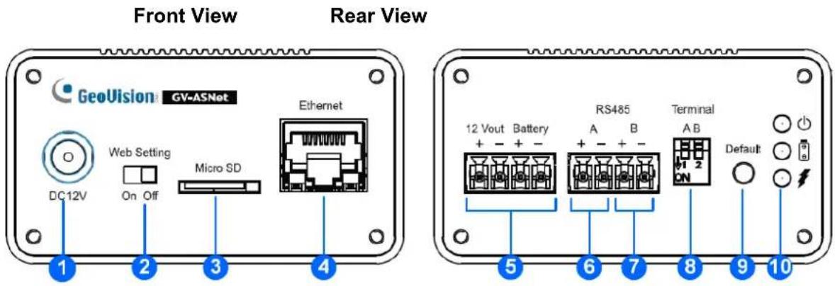
Figure 9-9
| No. | Name Function | |
| 1 | DC Power Input (12V) Connects to power supply. | |
| 2 | Web Setting | Enables the Advanced Settings on Web interface of GV-AS100/GV-AS110/GV-AS120. |
| 3 | Micro SD The Micro SD slot is not functional at this point. | |
| 4 | Ethernet Connects to the network. | |
| 5 | 12V+/12V- Battery Power supply for GV-AS100/GV-AS110/GV-AS120. | |
| 6 | RS485A+/RS485A- Connects to GV-AS100/GV-AS110/GV-AS120. | |
| 7 | RS485B+/RS485B- Connects to GV-Readers. | |
| 8 | Terminal A/B Enables RS-485 interface. | |
| 9 | Default button Resets all configurations to factory defaults. | |
| 10 | Power LED | Shows the power source and battery charging status of the GV-ASNet. See 9.2.4.C Other Settings for more details. |
9.2.4 Installation
This section describes how to connect other devices to GV-ASNet.
9.2.4.A Connecting GV-AS100 / 110 / 120
The table and figure below show the pin assignments of related connectors on the rear view of the GV-ASNet for connection to GV-AS100 / 110 / 120.
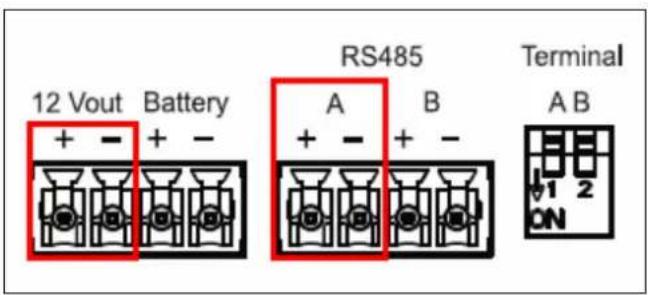
Figure 9-10
| Pin Function Pin Function | |||
| 12V+ | 12V Power Supply to GV-AS100 / 110 /120 | 12V- | GND for Power Supply to GV-AS100 / 110 / 120 |
| RS485A+ | GV-AS100 / 110 / 120 Connection | RS485A- | GV-AS100 / 110 / 120 Connection |
Note:
- By default, RS-485_A Term and RS-485_B Term are set to OFF.
- When the distance between the GV-ASNet and the GV-AS100 / 110 / 120 is over 600 meters, RS-485_A Term must be switched to ON. When the distance between the GV-ASNet and the GV-Readers is over 600 meters, RS-485_B Term must be switched to ON.
9.2.4.B Connecting GV-Readers and GV-GF Fingerprint Readers
You can connect up to 2 units of GV-Readers and GV-GF Fingerprint Readers to GV-ASNet. Multiple GV-Readers and GV-GF Fingerprint Readers can be connected with a single RS-485 cable to the RS485 B+ and B- on GV-ASNet. You will need to connect the GV-Readers or GV-GF Fingerprint Readers to external power supply.
The figure and table shows the pin assignments for related connectors.
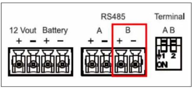
Figure 9-11
| Pin Function Pin Function | |||
| RS485B+ | GV-Reader / GV-GFFingerprint ReadersConnection | RS485B- | GV-Reader / GV-GFFingerprint ReadersConnection |
To define each GV-Reader and GV-GF Fingerprint Reader, you need to use the GV-AS100 / 110 / 120 Web interface. See 9.3.2.G Extended Reader.
9.2.4.C Connecting Backup Battery
You can connect any battery of 12V 12Ah to GV-ASNet to provide backup power when the main power supply fails. When the main power supply is removed and the battery voltage level is above 10.2V, the battery will support normal operation of the GV-ASNet.
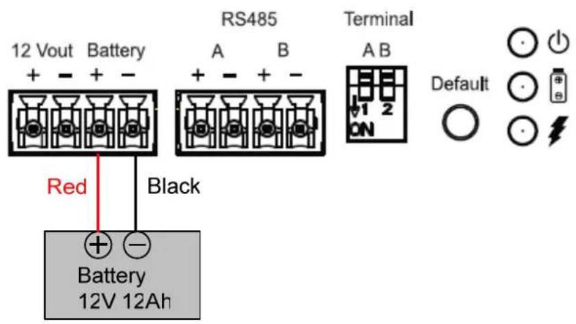
Figure 9-12
9.2.4.D Other Settings
The figure below shows the location of the Web Setting Switch, Default Button and Power Status LED.
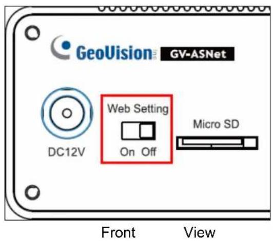
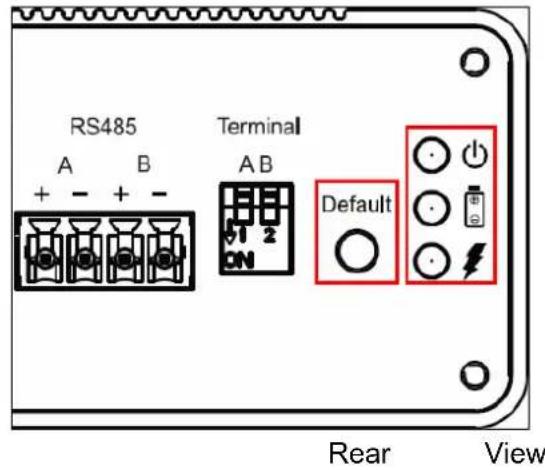
Figure 9-13
9.2.4.D.a Web Setting Switch
When the Web Setting switch is set to ON, you can modify Advanced Settings of GV-AS100 / 110 / 120 through the Web interface. When the switch is set to OFF, Advanced Settings are not accessible. For details on Advanced Settings, see 9.3.2 Advanced Settings.
9.2.4.D.b Restoring Factory Defaults
To restore factory default values, press the Default button on GV-ASNet for 6 seconds. After this it may take up to 3 minutes to restore GV-ASNet to default values.
9.2.4.D.c Power Status LED
The three LED located on the right of the rear panel indicate the power status of the GV-ASNet. When the power LED ⏻ is red, it indicates that the GV-ASNet is powered. When the main power source is off and that the GV-ASNet is running on battery, the battery LED 📋 turns green. An orange charging LED 🔒 means that the battery is being charged.
9.2.5 GV-ASNet Specifications
| CPU 32-bit ARM7TDMI Microprocessor | ||
| Power 100 ~ 240V AC, 50 ~ 60 Hz | ||
| Battery 12V, 5Ah and 12V, 12Ah | ||
| RS-485 Interface | 1 RS-485 interface only for GV-Readers and GV-GF Fingerprint Readers (Max. 2 readers) | |
| Communication Protocol | GV-AS100/110/120 RS-485 | |
| GV-ASManager TCP/IP (10/100 Mbps Ethernet) | ||
| Operating Temperature 0 ~ 65°C / 32 ~ 149°F | ||
| Operating Humidity 10% ~ 90% RH (non-condensing) | ||
| Dimensions (W X H X D) 118.3 x 74 x 40 mm / 4.7 x 2.9 x 1.6 in | ||
| Weight 300 g / 0.66 lb | ||
| Certification CE, FCC, RoHS | ||
All specifications are subject to change without notice.
9.3 Web Interface through Optional Devices
Through GV-ASBox or GV-ASNet, you can access the GV-AS100 / GV-AS110 / GV-AS120's Web interface. Also through GV-ASBox or GV-ASNet, GV-AS100, GV-AS110 or GV-AS120 can communicate with GV-ASManager over the network.
GV-ASBox and GV-ASNet must be assigned an IP address to make it accessible on the network. Refer to Chapter 7 Installing on a Network for detailed instructions.
The Web interface is divided into three sections: Basic Setting, Advanced Setting and Extended Device.
9.3.1 Basic Setting
The Basic Setting section consists of four setup pages:
| Category Setting | Description | |
| Basic Setting | Network Setting | There are different methods to install GV-ASBox and GV-ASNet on the network. See Chapter 8 Installing on a Network. |
| Other Setting | See 9.1.1 System Setup. | |
| Firmware Upgrade | See 9.1.2 Upgrading Firmware. | |
| Account Setting | See 9.1.3 Changing Login ID and Password. |
9.3.2 Advanced Settings
You can execute and edit door/Wiegand operations and settings, turn on Alarms, view status, display card information stored in GV-AS100 / 110 / 120, set the device time and edit the input/output functions.
The changes in some of the Advanced Setting page will effect the options available on other pages. The diagram below shows the relationships between each Advanced Setting page.
The Relationship Diagram between each Advanced Setting Page
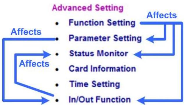
flowchart
graph TD
    A["Affects"] --> B["Advanced Setting"]
    B --> C["Function Setting"]
    B --> D["Parameter Setting"]
    B --> E["Status Monitor"]
    B --> F["Card Information"]
    B --> G["Time Setting"]
    B --> H["In/Out Function"]
    I["Affects"] --> B
Figure 9-14
Note: The Status Monitor and In/Out Function pages are only available when connecting through a GV-ASBox.
9.3.2.A Function Setting
In the left menu, click Function Setting. This AS100/AS110/AS120 Function Configuration page appears.
Note: The Wiegand settings and Door/Gate B settings are only available when connecting through GV-ASBox.
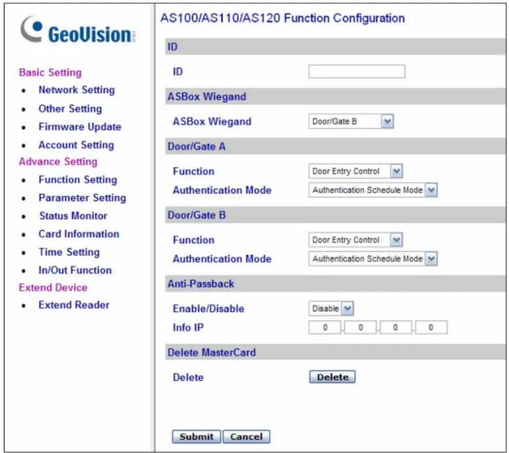
Figure 9-15
[ID]
Enter the ID number for GV-AS100, GV-AS110 or GV-AS120. This ID is used by GV-ASManager to differentiate among multiple units of GV-AS100 / 110 / 120. ID number can only be between 1 and 255.
[ASBox Wiegand]
This option is only available for GV-ASBox. Select the function for Wiegand Input on GV-ASBox from the drop-down list.
■ No Function: Wiegand Input is not in use.
■ Door/Gate A Entry: Wiegand Input becomes the entry point for Door/Gate A.
■ Door/Gate A Exit: Wiegand Input becomes the exit point for Door/Gate A.
■ Door/Gate B: Wiegand Input becomes Door/Gate B.
[Door/Gate A]
Select the function type and authentication mode for the use of Door/Gate A.
■ Function: Select the function for GV-AS100 / 110 / 120 on Door/Gate A.
- Door Entry Control: Sets GV-AS100 / 110 / 120 as entry reader on the Door A. The Wiegand reader connected on GV-AS100 / 110 / 120 will be set as exit reader.
Door Exit Control: Sets GV-AS100 / 110 / 120 as exit reader on the Door A. The Wiegand reader connected on GV-AS100 / 110 / 120 will be set as entry reader.
Parking Entry Control: Sets GV-AS100 / 110 / 120 as entry reader on the parking Gate A.
Parking Exit Control: Sets GV-AS100 / 110 / 120 as exit reader on the parking Gate A. - Elevator Control: GV-AS100 / 110 / 120 is installed in the elevator for access control.
Note: The Parking Entry Control and Parking Exit Control only work when the sensor input of Car Detection is activated. When the card is present but the sensor input is not activated, the message "No Car In Zone" will appear in the GV-AS100 LCD.
■ Authentication Mode: Select the authentication mode for the Door/Gate A.
- Local Unlock Mode: Remains open. The held-open state cannot be cleared through GV-ASManager.
- Local Lock Mode: Remains locked. The locked state cannot be cleared through GV-ASManager.
-
Fixed Card Mode: Grants access after the card is presented, and ignores the authentication schedule of GV-ASManager.
-
Fixed Card + PIN Mode: Grants access after the user presents the card and then enters the card's PIN code, and ignores the authentication schedule of GV-ASManager.
- Fixed Card/Common mode: Grants access after the user presents the card or enters the door's password, and ignores the authentication schedule of GV-ASManager.
- Authentication Schedule Mode: Follows the authentication schedule set on GV-ASManager.
[Door/Gate B]
This option is only available for GV-ASBox and only becomes available after Door/Gate B is selected from the ASBox Wiegand option above.
Select the function type and authentication mode for the use of Door/Gate B. The Function and Authentication Mode options are the same as those of Door/Gate A. But remember that the settings here are used to define the Wiegand reader connected to GV-ASBox.
[Anti-Passback]
This setting lets you perform Anti-Passback applications across multiple GV-AS Controllers. Anti-Passback prevents use of a card to gain successive entries without exit to a controlled area. For details on setup, see Chapter 6 Anti-Passback on GV-ASManager User's Manual.
■ Enable/Disable: Enables or disables the Anti-Passback function.
■ Info IP: Enter the IP address of the next corresponding GV-AS100 / 110 / 120.
[Delete MasterCard]
■ Delete: Click the Delete button to delete the current MasterCard information.
Click Submit button to save the changes, or click Cancel button to return the changes to its previous state.
9.3.2.B Parameter Setting
In the left menu, click Parameter Setting. This AS100/AS110/AS120 Configuration page appears. The contents of Parameter Setting change based on your settings for Door/Gate A and Door/Gate B in the Function Setting page (Figure 9-15).
Note: The Door B settings and Input Name settings are only available when connecting through GV-ASBox.
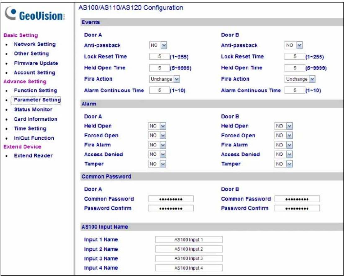
Figure 9-16
IMPORTANT: Once connecting to GV-AS100 / 110 / 120, GV-ASManager will load its parameters to the GV-AS Controller. That means some of the Parameter Settings you have configured here may be rewritten by GV-ASManager later.
[Events]
Set the parameters for the events.
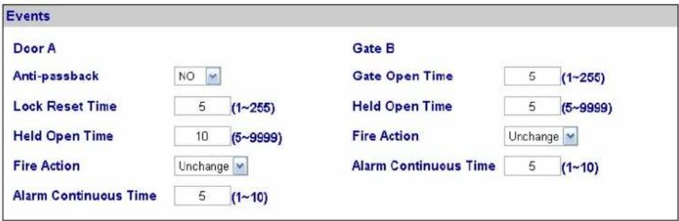
Figure 9-17
- When Door Entry/Exit Control or Parking Entry/Exit Control is selected in the Function Setting page (Figure 9-15), these options become available:
| Option Description | |
| Anti-Passback | Enables or disables the Anti-Passback function. The option is only available for Door/Gate A. |
| Gate Open Time | Sets the time (1 to 255 sec.) that a parking gate remains open after which the gate will automatically be locked. The option is only available when Parking Entry/Exit Control is selected. |
| Lock Reset Time | Sets the time (1 to 255 sec.) that a door remains open after which the door will automatically be locked. The option is only available when Door Entry/Exit Control is selected. |
| Held Open Time | Sets the time (5 to 9999 sec.) that a door/gate can be held open before an alarm is generated. |
| Fire Action | Locks or unlocks the door/gate when a fire condition occurs. Otherwise, remains the door's current state by selecting Unchanged. |
| Alarm Continuous Time | Sets the time (1 to 10 sec.) that the alarm will continuously go off before it ends. |
- When Elevator Control is selected in the Function Setting page (Figure 9-15), these options become available:
| Option Description | |
| Relay on Time | Sets the time (1 to 255 sec.) that an elevator door remains open after which the door will automatically be closed. |
| Fire Action | See the same option above. |
| Alarm Continuous Time |
[Alarm]
Select Yes or No to enable or disable the alarm function. If you have defined the alarm conditions in [Output Function] of the In/Out Function page (Figure 9-23), remember to activate the corresponding alarms here; otherwise, even though the alarm conditions are met, the expected alarm will not be triggered. The default settings for all the alarms are set to NO.
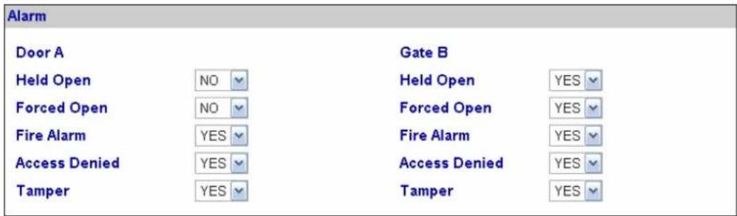
Figure 9-18
- When Door Entry/Exit Control or Parking Entry/Exit Control is selected in the Function Setting page (Figure 9-15), these options become available:
| Option Description | |
| Held Open | This alarm activates whenever the door is held open over the set period of time. |
| Forced Open | This alarm activates whenever the door is opened by force. |
| Fire Alarm This alarm | activates whenever fire is detected. |
| Access Denied | This alarm activates whenever entry is denied due to using the wrong card or entering the wrong password. |
| Tamper | This alarm activates whenever the controller is being physically tampered with, e.g. opening of the controller or sustaining strong impact. GV-AS100 / 110 / 120 have built-in sensors for tampering alarm. |
- When Elevator Control is selected in the Function Setting page (Figure 9-15), these options become available:
| Option Description | |
| Fire Alarm | See the same option above. |
| Access Denied | |
| Tamper |
[Common Password]
When Fixed Card/Common Mode is selected as Authentication Mode in the Function Setting page (Figure 9-15), you can gain access by using the card or entering this Common Password (door's password).
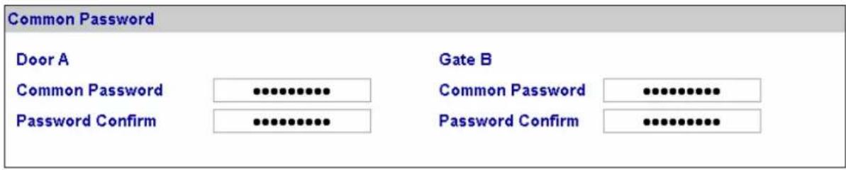
Figure 9-19
[AS100 Input Name]
This option is only available for GV-ASBox. Rename the input names by clicking Submit button to save the changes, or click Cancel button to return the changes to its previous state.
9.3.2.C Status Monitor
In the left menu, click Status Monitor to see the status of each input, output and alarm
Note: The Status Monitor page is only available when connecting through a GV-ASBox.
| GeoVision Basic Setting • Network Setting • Other Setting • Firmware Update • Account Setting Advance Setting • Function Setting • Parameter Setting • Status Monitor • Card Information • Time Setting • In/Out Function Extend Device • Extend Reader | Control Mode | Memory Status | ||
| Door | Local Unlock Mode | Used / Capacity | 36 / 65535 | |
| Door Contact A | Events | |||
| AS100 Input 1 | OFF | Alarm | Tamper | |
| Exit Button A | Forced Open | FireAlarm | ||
| AS100 Input 2 | OFF | Duress | Held Open | |
| Fire Zone A | Electric Lock A | |||
| ASBOX Input 3 | OFF | ASBOX Output 1 | ON | |
| AS100 Input 3 | OFF | General Alarm A | ||
| Tamper Zone A | ASBOX Output 3 | OFF | ||
| ASBOX Input 4 | OFF | Lighting | ||
| AS100 Input 4 | OFF | ASBOX Output 5 | ||
| Normal Input | Normal Output | |||
| ASBOX Input 1 | OFF | ASBOX Output 6 | ||
| ASBOX Input 2 | OFF | Normal Output | ||
| ASBOX Input 5 | OFF | ASBOX Output 7 | ||
| ASBOX Input 6 | OFF | Normal Output | ||
| ASBOX Input 7 | OFF | ASBOX Output 8 | ||
| ASBOX Input 8 | OFF | |||
Figure 9-20
Control Mode will change depending on the chosen Door/Gate's Authentication Mode in the Function Setting page (Figure 9-15). The listed number of outputs will change depending on the chosen Output Type in the In/Out Function page (Figure 9-23).
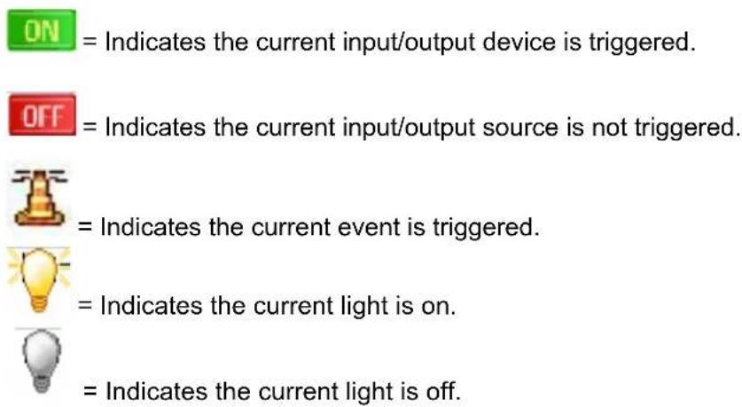
Note: Outputs must be turned on in the In/Out Function page to be monitored here.
9.3.2.D Card Information
In the left menu, click Card Information. This Card Configuration page appears.
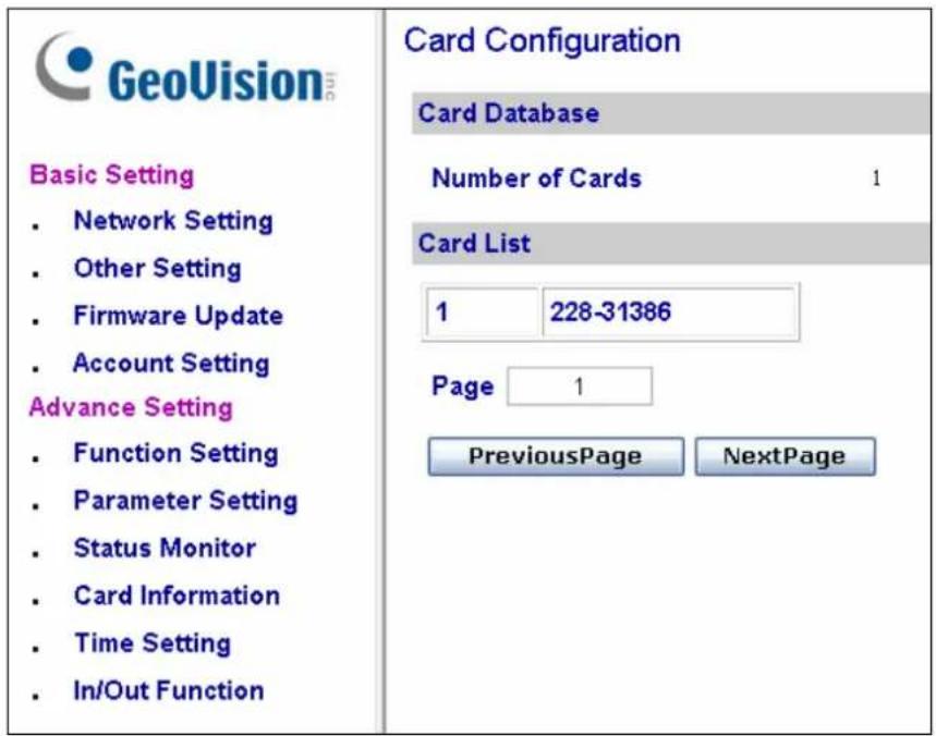
Figure 9-21
[Card Database]
Shows the number of cards currently stored in GV-AS100 / 110 / 120.
[Card List]
Displays the list of cards stored in GV-AS100 / 110 / 120. If there are many pages, you can choose to jump to any page by entering the page number in the Page field.
Click Previous Page button to go to the previous page of the Card List, or click Next Page button to go to the next page of the Card List.
9.3.2.E Time Setting
In the left menu, click Time Setting. This Time Configuration page appears.
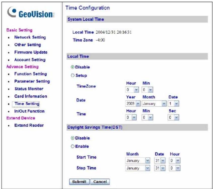
Figure 9-22
[System Local Time]
■ Local Time: Displays the current date and time of GV-AS100 / 110 / 120.
■ Time Zone: Displays the current time zone of GV-AS100 / 110 / 120.
[Local Time]
■ Disable: Disable the manual configuration of time and date.
■ Setup: Enable the manual configuration of Time Zone, Date and Time for GV-AS100 / 110 / 120.
[Daylight Savings Time (DST)]
■ Disable: Disable the manual configuration of DST.
■ Time Zone: Enable the manual configuration of DST by setting the Start Time and Stop Time for the DST period.
Click Submit button to save the changes, or click Cancel button to return the changes to its previous state.
9.3.2.F In/Out Function
In the left menu, click In/Out Function to define the input and output sensors.
Note: The I/O Configuration page is only available when connecting through a GV-ASBox.
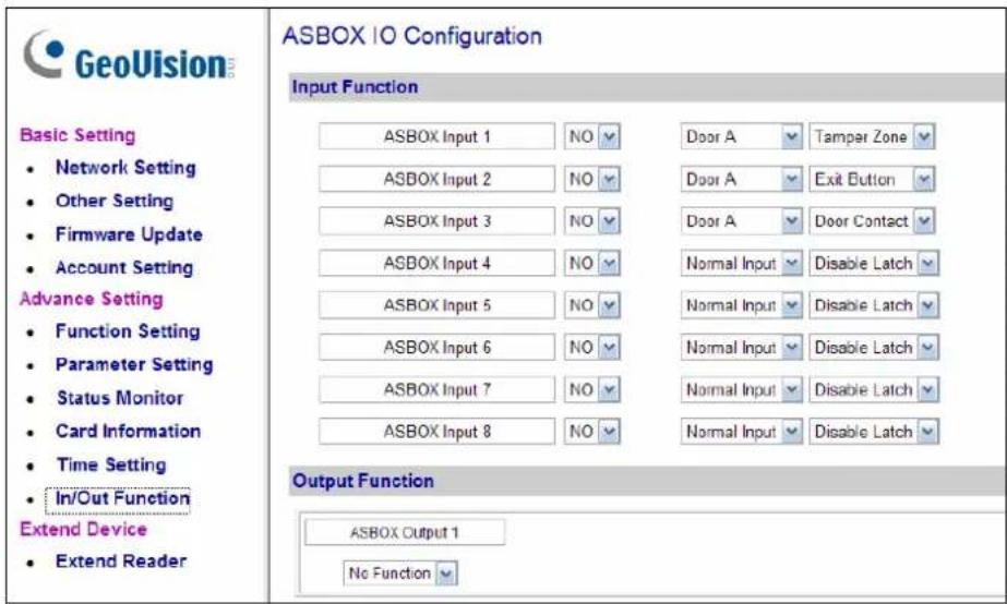
Figure 9-23
[Input Function]
Here you can define each sensor input that is connected GV-ASBox and select the most fitting Input Type (No. 3, Figure 9-24) and Input Function (No. 4, Figure 9-24) to describe the sensor input. Through the sensor input, an alarm event can be detected and it can then trigger the alarm device.
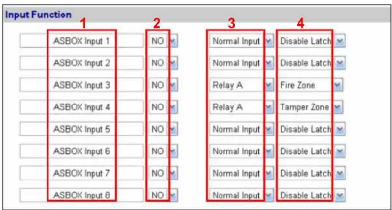
Figure 9-24
Below is the explanation based on the numbers marked on the above figure.
- ASBOX Input #: Edit the name of the Input.
-
NO/NC: Configure the input to NC (normally closed) or NO (normally open) mode.
-
Input Type: Configure the input type to define the type of sensor that is connected to the input of GV-ASBox. Options available for the input type change based on your settings of Door/Gate A and Door/Gate B in the Function Setting page (Figure 9-15).
-
Input Function: Configure the input function. Options available for the input function change based on the settings of Input Type above.
- When Door Entry/Exit Control is selected in the Function Setting page (Figure 9-15), these Input Type and Input Function become available:
| Input Type Input Function Description | ||
| Normal Input Enable | LatchDisable Latch | The Normal Input is used for a normal detection mode in which the input is set to trigger an output. Instead of constant output alarm in N/O and N/C, theEnable Latchoption provides a momentary alarm when triggered. |
| Door A or B Fire Zone | Tamper ZoneExit ButtonDoor Contact | Depending on the type of sensor and the location where it is installed, select the best Input Function name to fit the sensor description. When the sensor is activated, an alarm event occurs and the alarm device can be triggered. For alarm events, see [Alarm], 9.3.2.B Parameter Setting.For example, when theDoor Contactsensor detects unauthorized access, a “Force Open” event occurs and it can trigger the “Force Open” alarm. |
- When Parking Entry/Exit Control is selected in the Function Setting page (Figure 9-15), these Input Type and Input Function become available:
| Input Type Input Function Description | ||
| Normal Input Enable | LatchDisable Latch | See the same Input Type above. |
| Gate A or B Fire Zone | Tamper ZoneExit ButtonCar Detection | See the “Doo A or Door B” Input Type above.For example, when the Car Detection sensor detects any car driving by, a “Parking Entry” or “Parking Exit” event occurs and the parking gate will respond the event accordingly. |
- When Elevator Control is selected in the Function Setting page (Figure 9-15), these Input Type and Input Function become available:
| Input Type Input Function Description | ||
| Normal Input Enable | LatchDisable Latch | See the same Input Type above. |
| Relay A or B Fire Zone | Tamper Zone | See the “Door A or Door B” Input Type above.For example, the Tamper Zone sensor is installed on GV-ASBox. So whenever there is any attempt to open the Box, the “Tamper” event occurs and it may trigger the “Tamper” alarm. |
Note: For alarm outputs, the corresponding alarms must be enabled (YES) in the Parameter Setting page (Figure 9-16). If alarms are set to be disabled (NO), the alarm function here will not work when triggered.
[Output Function]
Here you can define each output device that is connected to GV-ASBox, such as locking devices, various alarms or Exit Button. Only Output 5 to Output 8 can be connected to Lights.
Select from the drop-down list to configure Output Type (No. 1, Figure 9-25). Depending on the chosen Output Type, either Output Function (No. 2, Figure 9-25) or Output Conditions (No. 3, Figure 9-25) will become available.
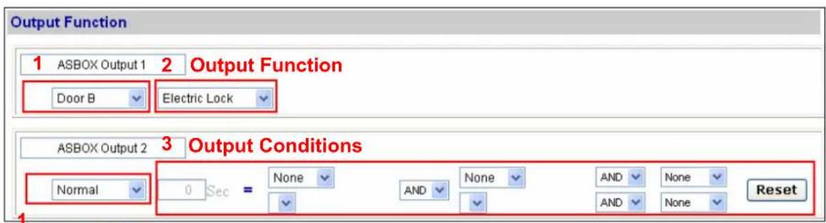
Output Type
Figure 9-25
Output Function Settings:
When Output Type (No. 1, Figure 9-25) is set to be Door #, Gate # or Relay #, the options similar to the figure below become available.

Figure 9-26
Below is the explanation based on the numbers marked on the above figure.
- ASBOX Output #: Edit the name of the Output.
- Output Type: Configure the output type. Options available for the output type change based on your settings of Door/Gate A and Door/Gate B in the Function Setting page (Figure 9-15).
- Output Function: Configure the output function. Options available for the output function change based on your setting of Output Type above.
- When Door Entry/Exit Control is selected in the Function Setting page (Figure 9-15), these Output Type and Output Function become available:
| Output Type Output Function Description | ||
| Door # | Electric Lock | Output is triggered when the card is presented to open the locking device. |
| Alarm Event | Output is triggered when the defined alarm events occur. | |
| Entry Card | Output is triggered when the card is presented to enter the door. | |
| Exit Card | Output is triggered when the card is presented to exit the door. | |
- When Parking Entry/Exit Control is selected in the Function Setting page (Figure 9-15), these Output Type and Output Function become available:
| Output Type Output Function Description | ||
| Gate # | Electric Lock | See the same function above. |
| Alarm Event | ||
| Entry Card | Output is triggered when the card is presented to enter the parking gate. | |
| Exit Card | Output is triggered when the card is presented to exit the parking gate. | |
- When Elevator Control is selected in the Function Setting page (Figure 9-15), these Output Type and Output Function become available:
| Output Type Output Function Description | ||
| Electric Lock Relay # | See the same function above. | |
| Alarm Event | ||
Output Condition Settings:
When Output Type (No. 1, Figure 9-25) is set to be Normal, Toggle, Pulse, Normal Lighting, Toggle Lighting or Pulse Lighting, the options similar to the figure below become available.

Available in
Pulse/Lighting
Figure 9-27
There can be a maximum of 4 conditions that can be set up to trigger an output. 2 conditions are Door/Gate/Relay conditions and 2 conditions are Input conditions. Each condition is related to each other through AND/OR. AND means that all conditions with AND must be triggered before the output is triggered. OR means that only 1 of the condition with OR is needed to be triggered before the output is triggered. It is also valid to have certain conditions as AND and certain conditions as OR.
Only Output 5 \~ 8 can be connected to Lights. So Normal Lightning, Toggle Lighting and Pulse Lighting can only be selected from Output 5 \~ 8. For Pulse and Pulse Lighting, the output is triggered for the amount of time set in the Sec field (seconds).
In the Output Condition Settings, these Output Type and Output Condition options become available:
| Output Condition Output Type | ||||
| Door A or B | Gate A or B | Relay A or B | Input (x2) | |
| Normal Toggle Pulse Normal Lighting Toggle Lighting Pulse Lighting | Access Granted | Access Granted Access Granted | Access Granted | Select None to disable the condition, or select between Input 1 and Input 8 to trigger the output. |
| Access Denied | Access Denied Access Denied | |||
| Fire Alarm Fire Alarm | Fire Alarm | |||
| Tamper Tamper | Tamper | |||
| Duress Event Duress Event Duress Event | ||||
| Held Open Held | Open | |||
| Forced Open Forced Open | ||||
| Exit Button Exit Button | ||||
| Door Contact Car Detection | ||||
Click Reset button to return the Normal, Toggle, Pulse, Normal Lighting, Toggle Lighting or Pulse Lighting triggered state to be normal.
Note: The Reset button is more commonly used for the Toggle or Toggle Lighting output. Because once triggered, the output will go on forever. A Reset button is needed to turn it off.
Click Submit button to save the changes, or click Cancel button to return the changes to its previous state.
9.3.2.G Extended Reader
In the left menu, click Extend Reader. This Extend Reader Configuration page appears.
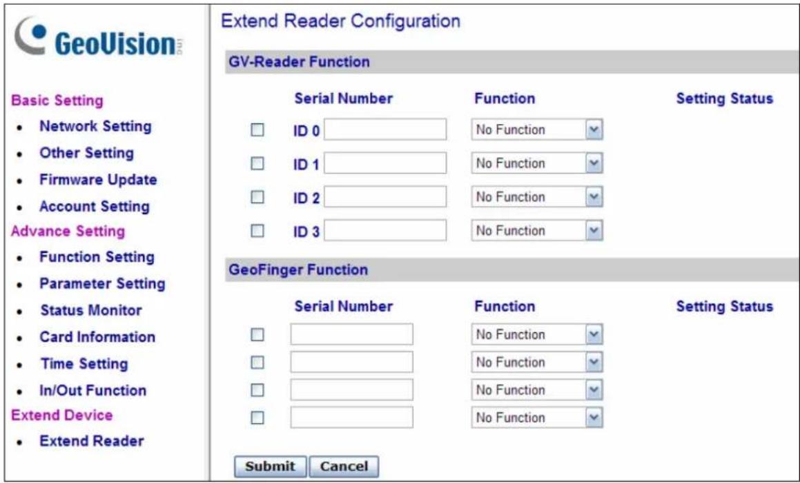
Figure 9-28
Define the readers connected to GV-AS100 / 110 / 120, and then use the Function drop-down list to select which door that the GV-Reader/GV-GF Fingerprint Reader is installed.
[GV-Reader Function]
- GV-RK1352 / R1352 / DFR1352: Select the checkbox and type the Serial Number of the reader. Note that the ID number located next to the serial number field need to match the reader's ID number defined through the GV-RK1352 Config AP.
- GV-Reader 1251 / Reader 1352 V2: Select the checkbox and leave the serial number field blank. Note that the ID number located next to the serial number field need to match the reader's ID number defined by the dip switches on the reader.
- GV-CR420: Type the Barcode of GV-CR420. Select the checkbox only if the GV-CR420 is connected to the controller through RS-485 connection. For network connection, do not select the checkbox. Note that only GV-CR420 V1.0 is compatible with GV-AS100 / 110 / 120 and you must also enable network connection to the controller on the Web interface of the GV-CR420.
[GeoFinger Function] For GV-GF1901 / GF1902 / GF1911 / GF1912, select the checkbox and type the XID Number located on the back of the reader.
Click Submit to detect the readers. If any GV-Reader / GV-GF Fingerprint Reader is detected, a green mark will appear in the Status field; if not, a red mark will appear.
10. Troubleshooting
Q1: GV-ASManager cannot connect to GV-AS/ GV-EV Controller over the Internet.
There are several causes for this problem such as IP address conflict, incorrect connection settings and network failure. Follow the steps below to assign the fixed IP to the GV-ASManager and GV-AS / GV-EV Controller respectively. This procedure can determine if the problem is caused by the faulty devices and incorrect network settings.
- Disconnect the hub or switch, which connects the GV-ASManager and GV-AS / GV-EV Controller, from the network.
- Give the GV-ASManager a fixed IP address that is NOT used by another device, e.g. 192.168.0.154.
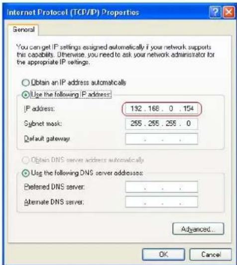
Figure 10-1
- Reset the controller module and Ethernet module to factory defaults.
a. Plug the GV-ASKeypad to the controller.
b. Remove the jumper cap from the 2-pin Default jumper.
c. Press the Reset button.
d. Replace the jumper cap back to the 2-pin Default jumper.
e. To reset the Ethernet Module, press and hold the Default EN button for 6 seconds.
- Open the browser and enter the controller default address: http://192.168.0.100
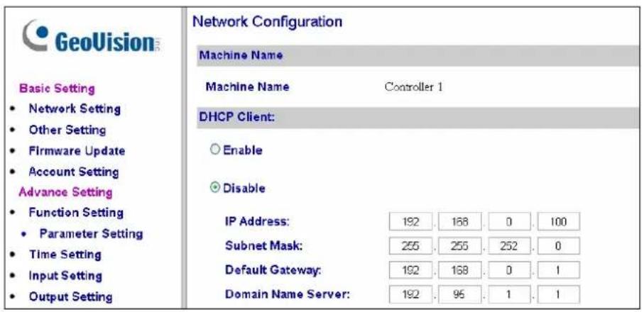
Figure 10-2
- In the IP address field, give the controller an IP address that is NOT used by another device, e.g. 192.168.0.XXX.
- On the GV-ASManager, enter the following settings:
Controller ID: 1
Network: TCP/IP
IP: 192.168.0.XXX
Port: 4000
User: admin
Password: admin
Crypto key: 12345678
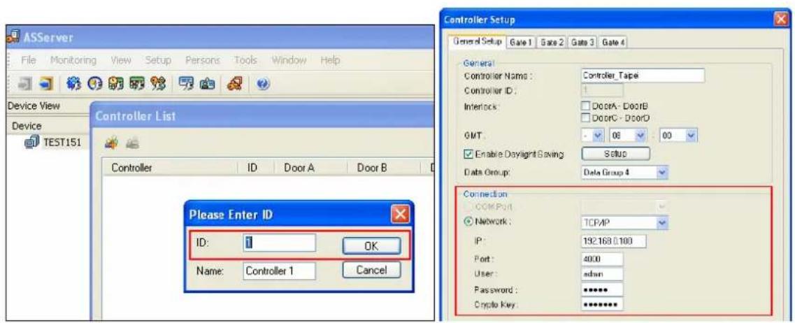
Figure 10-3
- The connection between the GV-ASManager and controller should be established, and the connection icon should appear. If disconnection happens after you connect the hub or switch to the network, then it should be other network problems. Please contact your network administrator.
Q2: The connection established between the GV-ASManager and GV-AS / GV-EV Controller is interrupted.
This may be due to IP address conflict. Follow these steps to troubleshoot the problem:
- Disconnect the hub or switch, which connects to the GV-ASManager and the controller, from the network.
- Run Windows Command Prompt. Take Classic Windows Start Menu for example, click Start, select Accessories and click Command Prompt.
- Type arp -d and press Enter.
![C:\WINDOWS\system32\cmd.exe Microsoft Windows XP [Version 5.1.2600] (C) Copyright 1985-2001 Microsoft Corp. C:\Documents and Settings\joyce>arp -d_](/content/2026/05/1004733/images/c45fe1a6629e001d23c48c951c18bb2070af1f19b3721ee4e0e2c62d1c12785c.jpg)
Figure 10-4
-
Give the GV-ASManager a fixed IP address that is NOT used by another device. See Figure 10-1.
-
Open the browser and enter the assigned IP address of the controller. The Network Configuration page appears. See Figure 10-2.
-
In the IP address field, give the GV-AS / GV-EV Controller an IP address that is NOT used by another device, e.g. 192.168.0.XXX.
-
On the GV-ASManager, enter the following settings. See Figure 10-3.
Controller ID: 1
Network: TCP/IP
IP: 192.168.0.XXX
Port: 4000
User: admin
Password: admin
Crypto key: 12345678
- The connection between the GV-ASManager and GV-AS Controller should be established, and the connection icon should appear. If disconnection happens after you connect the hub or switch to the network, then it should be other network problems. Please contact your network administrator.
Q3: GV-ASManager cannot receive card messages but the reader accepts the card when the connection between the GV-ASManager and GV-AS / GV-EV Controller is well established.
It may be due to memory failure in the GV-AS / GV-EV Controller. Reset both the controller module and the Ethernet module to factory settings. Refer to Step 3 in Question 1.
Q4: The GV-ASManager cannot retrieve the video from the DVR for playback.
- Make sure the Remote ViewLog Service on Control Center Server is enabled on the DVR.
- Make sure the time on the GV-ASManager and the DVR is consistent.
- Make sure the event file you want to play back has been created completely on the DVR. For example, the assigned time length of every recorded event on the DVR is 5 minutes. The desired event of 5 minutes must have been displayed on the ViewLog Event List, so you can access the event file for playback.
Q5: After I add a card by presenting to the reader, the message “Access Denied Invalid Card” still appears.
It may be the card format is not compatible with the GV-AS / GV-EV Controller. Make sure the card format is 26\~64 bits. Otherwise, send us the related information of your card format so that we can customize the format for you.
Q6: The GV-ASManager cannot receive card messages from the GV-Reader connected to the GV-AS / GV-EV Controller through RS-485 interface.
- Make sure the GV-Reader is correctly wiring to the controller and Switch 4 on the GV-Reader is set to OFF.
- Make sure the correct GV-Reader ID is set on the controller.
Q7: I can't change the Advanced Settings on the Web interface of the GV-AS / GV-EV Controller. The "Submit" button is missing.
To modify the Advanced Settings, make sure the Web Setting Switch on the controllers is set to ON. For the location of the Web Setting Switch, refer to the Web Setting Switch section of each GV-AS / GV-EV Controller or GV-ASNet / GV-ASBox.
Q8: After installing GV-ASManager, the message "d3dx9_40.dll cannot be found" appears.
Make sure DirectX End-User Runtimes is installed and restart the computer afterwards. To install DirectX End-User Runtimes, insert the supplied Software DVD to your computer, and select Install DirectX End-User Runtimes (November 2008).
Q9: How can I find more help?
Visit our website at http://www.geovision.com.tw
Write to us at support@geovision.com.tw
Appendix
A. GV-MountA900 for GV-AS110 / 1110
(Optional)
GV-MountA900 is an optional mounting plate that allows you to attach GV-AS110 / 1110 to a US single gang power box.
• Dimensions: 100 x 68 mm / 3.9 x 2.7 in
• Weight: 55 g / 0.12 lb
Connecting GV-MountA900
- Attach GV-MountA900 to the US single gang power box by securing the screws for holes C as shown below.
- Attach GV-AS110 / 1110 to GV-MountA900 by securing the screws for holes B as shown below.
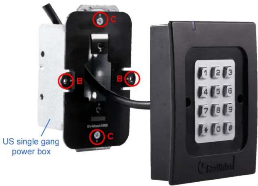
- GeoVision Inc
- © 2015 GeoVision, Inc. All rights reserved.
- Contents
- Welcome...... vii
- Important Notes for Maintaining Power Supply...... viii
- Elevator Control....x
- Optional Devices xi
- Installation Considerations...... xiii
- Firmware and Software Compatibility ....xiv
- Definition....xv
- GV-AS100 / 1010 Controller .... 1
- Introduction....2
- Installation....7
- Programming Mode....20
- GV-AS110 / 1110 Controller .... 34
- GV-AS120 Controller 59
- Programming Mode....69
- LED Status and Beeper 71
- GV-AS210 / 2110 Controller 74
- Introduction....75
- Installation....77
- Other Settings....84
- The Web Interface....86
- GV-AS210 / AS2110 Specifications 87
- GV-AS410 / 4110 / 810 / 8110 Controller 88
- Introduction....89
- Installation....92
- GV-EV48 Controller 107
- Installing on a Network 118
- The Web Interface...... 128
- Optional Devices 163
- Welcome
- Important Notes for Maintaining Power Supply
- Replaceable Button Cell (GV-AS100 / 2110 / 4110 / 8110)
- Built-in Battery (GV-AS1010 / 110 / 1110 / 120 / 210 / 410 / 810 & GV-EV48)
- Elevator Control
- Optional Devices
- Installation Considerations
- Firmware and Software Compatibility
- Definition
- Introduction
- Main Features
- GV-AS100
- GV-AS1010
- Packing List
- GV-AS100 / 1010 Board Layout
- Installation
- Connecting Card Readers
- 1.2.1.A Wiegand Readers (GV-AS100 Only)
- 1.2.1.B RS485 Readers
- 1.2.1.C Network Readers (GV-AS1010 Only)
- Note:
- Connecting Input Devices
- Connecting Output Devices
- To connect an output device:
- Connecting the PC
- GV-AS100: RS-485 connection or network connection
- 1.2.4.A Connecting GV-AS100 to PC
- RS-485 Connection between GV-AS100 and PC
- Network Connection between GV-AS100 and PC
- 1.2.4.B Connecting GV-AS1010 to PC
- 1.2.4.C Switches (GV-AS100 Only)
- Connecting the Power
- Fitting the Battery
- Using the Function Keys (GV-AS1010 Only)
- Programming Mode
- To create a Master Card for GV-AS100:
- To create a Enroll Card and a Delete Card for GV-AS1010:
- Quick Reference of Programming Table
- Adding and Deleting a Card
- 1.3.2.A Adding a Card
- 1.3.2.B Deleting a Card
- Resetting the APB Function
- Accessing the Security Mode
- 1.3.4.A Enabling the Security Mode
- 1.3.4.B Disabling the Security Mode
- Setting Parameters
- Displaying System Information
- Restoring Factory Defaults
- Web-Based Configurations
- GV-AS100 / 1010 Specifications
- Introduction
- Main Features
- GV-AS110
- GV-AS1110
- Packing List
- Installation
- Connecting Card Readers
- 2.2.1.A Wiegand Readers (GV-AS110 Only)
- 2.2.1.B Network Readers (GV-AS1110 Only)
- Connecting Input Devices
- Connecting Output Devices
- Connecting to the PC
- 2.2.4.A Connecting GV-AS110 to PC
- RS-485 Connection between GV-AS110 and PC
- Network Connection between GV-AS110 and PC
- 2.2.4.B Connecting GV-AS1110 to PC
- Connecting the Power
- Programming Mode
- To create the Enroll Card and the Delete Card:
- Adding and Deleting Cards
- 2.3.1.A Adding a Card
- 2.3.1.B Deleting a Card
- Programming the GV-AS110 / 1110
- LED Status and Beeper
- Web-Based Configurations
- GV-AS110 / 1110 Specifications
- GV-AS120 Controller
- Introduction
- Main Features
- Packing List
- Installation
- Connecting a Wiegand Reader
- Connecting Input Devices
- Connecting Output Devices
- Connecting to the PC
- 3.2.4.A RS-485 Connection
- To define ID number, control type and authentication mode
- Figure 3-7
- 3.2.4.B Network Connection
- Connecting the Power
- Programming Mode
- Adding and Deleting Cards
- 3.3.1.A Adding a Card
- 3.3.1.B Deleting a Card
- LED Status and Beeper
- Web-Based Configurations
- Introduction
- Main Features
- Packing List
- GV-AS210 / 2110 Board Layout
- Installation
- Connecting Card Readers
- 4.2.1.A Wiegand Readers
- 4.2.1.B RS-485 Readers
- Connecting Input Devices
- Connecting Output Devices
- Connecting Backup Battery
- Connecting the Power
- Connecting the PC
- Fitting the Battery (GV-AS2110 Only)
- Other Settings
- Web Setting Switch
- Resetting the GV-AS210 / 2110
- Restoring Factory Defaults
- The Web Interface
- Introduction
- Main Features
- GV-AS410 / 4110
- GV-AS810 / 8110
- Packing List
- GV-AS410 / 4110/ 810 / 8110 Board Layout
- Installation
- Connecting Card Readers
- 5.2.1.A Wiegand Readers
- 5.2.1.B RS-485 Readers
- Connecting Input Devices
- Connecting Output Devices
- Connecting Backup Battery
- Connecting the Power
- Connecting the PC
- Other Settings
- Web Setting Switch
- Resetting the GV-AS410 / 4110 / 810 / 8110
- Restoring Factory Defaults
- GV-AS410 / 4110 / 810 / 8110 Kit (Optional)
- Packing List
- Overview
- Connecting the GV-AS410 / 4110 / 810 / 8110 Kit
- GV-AS410 / 4110 / 810 / 8110 Kit Specifications
- The Web Interface
- Introduction
- Main Features
- Packing List
- GV-EV48 Board Layout
- Installation
- Connecting RS-485 Card Readers
- Connecting Output Relay
- To connect output relay:
- Connecting Backup Battery
- Connecting the Power
- Connecting the PC
- Other Settings
- Web Setting Switch
- Resetting the GV-EV48
- Restoring Factory Defaults
- The Web Interface
- GV-EV48 Specifications
- Installing on a Network
- Fixed IP Connection
- DHCP Connection
- Connection over LAN
- Installing LocalDDNS Server
- Configuring Controller on LAN
- Connection over Internet
- Registering a DDNS Domain Name
- Configuring the GV-AS / GV-EV Controller on Internet
- Basic Settings
- System Setup
- Upgrading Firmware
- Changing Login ID and Password
- Advanced Settings
- Function Configuration
- [ID]
- [Door/Gate #] [Elevator]
- [Series Function (APB & Fire)]
- Parameter Configuration
- 8.2.2.A GV-AS1010 / 1110 / 210 / 2110 / 410 / 4110 / 810 / 8110
- [Events]
- [Alarm]
- [Common Password]
- 8.2.2.B GV-EV48
- [Unmanaged Output]
- Card Configuration
- Card Information
- Card Information
- Time Configuration
- [System Local Time]
- [Local Time]
- [Daylight Savings Time (DST)]
- Input Configuration
- Output Configuration
- 8.2.7.A Output Function Settings
- 8.2.7.B Output Condition Settings
- Wiegand Configuration
- Function Key Configuration
- Extended Device
- Extended Reader
- Optional Devices
- Optional GV-ASBox
- Main Features
- Packing List
- Installation
- 9.1.4.A Connecting GV-AS100 / 110 / 120
- 9.1.4.B Connecting a Wiegand Reader
- 9.1.4.C Connecting GV-Readers and GV-GF Fingerprint Readers
- 9.1.4.D Connecting Input Devices
- 9.1.4.E Connecting Output Devices
- To combine door access with relay activation:
- 9.1.4.F Connecting Backup Battery
- 9.1.4.G Other Settings
- 9.1.4.G.a Web Setting Switch
- 9.1.4.G.b Resetting the GV-ASBox
- 9.1.4.G.c Restoring Factory Defaults
- Optional GV-ASNet
- Main Features
- Packing List
- GV-ASNet Overview
- Installation
- 9.2.4.A Connecting GV-AS100 / 110 / 120
- 9.2.4.B Connecting GV-Readers and GV-GF Fingerprint Readers
- 9.2.4.C Connecting Backup Battery
- 9.2.4.D Other Settings
- 9.2.4.D.a Web Setting Switch
- 9.2.4.D.b Restoring Factory Defaults
- 9.2.4.D.c Power Status LED
- Web Interface through Optional Devices
- Basic Setting
- Advanced Settings
- 9.3.2.A Function Setting
- [ASBox Wiegand]
- [Door/Gate A]
- [Door/Gate B]
- [Anti-Passback]
- [Delete MasterCard]
- 9.3.2.B Parameter Setting
- [AS100 Input Name]
- 9.3.2.C Status Monitor
- 9.3.2.D Card Information
- [Card Database]
- [Card List]
- 9.3.2.E Time Setting
- 9.3.2.F In/Out Function
- [Input Function]
- [Output Function]
- Output Function Settings:
- Output Condition Settings:
- 9.3.2.G Extended Reader
- [GV-Reader Function]
- Troubleshooting
- Q1: GV-ASManager cannot connect to GV-AS/ GV-EV Controller over the Internet.
- Q2: The connection established between the GV-ASManager and GV-AS / GV-EV Controller is interrupted.
- Q3: GV-ASManager cannot receive card messages but the reader accepts the card when the connection between the GV-ASManager and GV-AS / GV-EV Controller is well established.
- Q4: The GV-ASManager cannot retrieve the video from the DVR for playback.
- Q5: After I add a card by presenting to the reader, the message “Access Denied Invalid Card” still appears.
- Appendix
- GV-MountA900 for GV-AS110 / 1110
- (Optional)
- Connecting GV-MountA900
Brand : Geovision
Model : GV-AS1010
Category : Access Control System