
POWX0561 - Saw VARO - Free user manual and instructions
Find the device manual for free POWX0561 VARO in PDF.


| Product Type | Electric Hand-Held Circular Saw |
| Brand | VARO |
| Model | POWX0561 |
| Power Supply | 220-240 V ~ 50/60 Hz |
| Power Input | 1500 W |
| Blade Diameter | 190 mm (7.5 in) |
| Cutting Depth at 90° | 65 mm |
| Cutting Depth at 45° | 45 mm |
| No Load Speed | 5000 min⁻¹ |
| Weight | 4.5 kg |
| Dimensions (L×W×H) | 350 × 250 × 280 mm |
| Cable Length | 2 m |
| Protection Class | Class II (Double Insulation) |
| Safety Features | Blade guard, spindle lock, safety switch |
| Maintenance | Regular cleaning, carbon brush inspection, blade sharpening |
| Spare Parts | Blades, carbon brushes, saw base, guide rails |
| Additional Features | Dust extraction port, parallel guide, laser guide (optional) |
Frequently Asked Questions - POWX0561 VARO
User questions about POWX0561 VARO
0 question about this device. Answer the ones you know or ask your own.
Ask a new question about this device
Download the instructions for your Saw in PDF format for free! Find your manual POWX0561 - VARO and take your electronic device back in hand. On this page are published all the documents necessary for the use of your device. POWX0561 by VARO.
USER MANUAL POWX0561 VARO
1 APPLICATION....3
2 DESCRIPTION (FIG. A) 3
3 PACKAGE CONTENT LIST....3
4 SYMBOLS 4
5 GENERAL POWER TOOL SAFETY WARNINGS....4
5.1 Work area 4
5.2 Electrical safety....4
5.3 Personal safety 5
5.4 Power tool use and care....5
5.5 Service....5
6 ADDITIONAL SAFETY INSTRUCTIONS FOR PLUNGE SAWS....6
7 CAUSES AND PREVENTION OF KICKBACK 6
8 ADJUSTMENTS....7
8.1 Plunge saw feature 7
8.1.1 Selector switch....7
8.2 Guide rails and clamps (Fig. 1)....7
9 PREPARATION....8
9.1 Mounting the plunge saw on the guide rail 8
10 OPERATION....8
10.1 Switching ON/OFF....8
10.2 Setting the cutting depth....8
10.3 Setting the cutting angle (Fig. 4)....8
10.4 Determine Cutting line (Fig. 5) 9
10.5 Straight cuts (90° cut)....9
10.6 Miter cuts (up to 48°) (Fig. 6)....9
10.7 Marked cutting 9
10.8 Plunge cuts 9
10.9 Replacing the saw blade....10
11 FINE ADJUSTMENT OF PLUNGE SAW PLAY ON GUIDE RAIL 10
12 CONNECTING RODS FOR GUIDE RAILS (FIG. 7)....10
POWERPLUS® HIGH QUALITY TOOLS
POWX0561 EN
13 GUIDE RAIL SPLINTER GUARDS (FIG. 8)....10
14 KICKBACK STOP....11
15 PLUNGE CUT WITH GUIDE RAIL 11
16 CLEANING AND MAINTENANCE....11
16.1 Cleaning....11
16.2 Checking and replacing the carbon brushes....11
16.3 Lubrication 12
17 TECHNICAL DATA....12
18 NOISE....12
19 SERVICE DEPARTMENT 12
20 STORAGE 12
21 WARRANTY....13
22 ENVIRONMENT 13
23 DECLARATION OF CONFORMITY 14
PLUNGE SAW 1200W POWX0560
1 APPLICATION
The plunge saw is intended to cut wood and similar materials, gypsum and cement-bonded fiber materials and plastic. With compatible special saw blades the plunge saw can also be used to cut aluminum.
It is not designed for commercial use.

The plunge saw is only to be used with a specifically designed guide rail. Installation in a different or homemade guide rail or workbench can cause serious accidents.

WARNING! Read this manual and general safety instructions carefully before using the appliance, for your own safety. Your power tool should only be passed on together with these instructions.
2 DESCRIPTION (FIG. A)
-
On/off switch
-
Lock-off button
-
Main handle
-
Auxiliary handle
-
Base
-
Anti-kickback knob
-
Adjustment knob for guide track
-
Bevel lock knob
-
Depth adjustment knob
-
Depth adjustment stopper
-
Depth scale
-
Blade
-
Slot for track
-
Cutting indicators
-
Cutting width indicators
-
Dust extraction outlet
-
Mode selector
-
Shaft lock
-
Carbon brush cap
-
Anchoring knob
3 PACKAGE CONTENT LIST
■ Remove all packing materials
■ Remove remaining packaging and transit supports (if existing)
- Check the completeness of the packing content
- Check the appliance, the power cord, the power plug and all accessories for transportation damages.
- Keep the packaging materials as far as possible till the end of the warranty period. Dispose it into your local waste disposal system afterwards.

WARNING Packing materials are no toys! Children must not play with plastic bags! Danger of suffocation!
Plunge saw
1 x blade
2 x Hex key
1 x Set of spare cole brushes
2 x clamps
4 x split tracks

When parts are missing or damaged, please contact your dealer.
4 SYMBOLS
In this manual and/or on the machine the following symbols are used:
 | Denotes risk of personal injury or damage to the tool. |  | In accordance with essential requirements of the European directive(s) |
 | Read manual before use |  | Always wear safety goggles |
 | Always wear protective gloves |  | "Class II - The machine is double insulated; Earthing wire is therefore not necessary |
5 GENERAL POWER TOOL SAFETY WARNINGS
Read all safety warnings and all instructions. Failure to follow all warnings and instructions may result in electric shock, fire and/or serious injury. Save all warnings and instructions for future reference. The term "power tool" in the warnings refers to your mains operated (corded) power tool or battery operated (cordless) power tool.
5.1 Work area
- Keep work area clean and well lit. Cluttered and dark areas invite accidents.
- Do not operate power tools in explosive atmospheres, such as in the presence of flammable liquids, gases or dust. Power tools create sparks which may ignite the dust or fumes.
- Keep children and bystanders away while operating a power tool. Distractions can cause you to lose control.
5.2 Electrical safety

Always check that the power supply corresponds to the voltage on the rating plate.
■ Power tool plugs must match the outlet. Never modify the plug in any way. Do not use any adapter plugs with earthed (grounded) power tools. Unmodified plugs and matching outlets will reduce risk of electric shock.
- Avoid body contact with earthed or grounded surfaces such as pipes, radiators, ranges and refrigerators. There is an increased risk of electric shock if your body is earthed or grounded.
- Do not expose power tools to rain or wet conditions. Water entering a power tool will increase the risk of electric shock.
- Do not abuse the cord. Never use the cord for carrying, pulling or unplugging the power tool. Keep cord away from heat, oil, sharp edges or moving parts. Damaged or entangled cords increase the risk of electric shock.
- When operating a power tool outdoors, use an extension cord suitable for outdoor use. Use of a cord suitable for outdoor use reduces the risk of electric shock.
- If operating a power tool in a damp location is unavoidable, use a residual current device (RCD) protected supply. Use of an RCD reduces the risk of electric shock.
5.3 Personal safety
☐ Stay alert, watch what you are doing and use common sense when operating a power tool. Do not use a power tool while you are tired or under the influence of drugs, alcohol or medication. A moment of inattention while operating power tools may result in serious personal injury.
Use safety equipment. Always wear eye protection. Safety equipment such as dust mask, non-skid safety shoes, hard hat, or hearing protection used whenever conditions require will reduce personal injuries.
☐ Avoid accidental starting. Ensure the switch is in the off position before plugging in. Carrying power tools with your finger on the switch or plugging in power tools that have the switch on invites accidents.
Remove any adjusting key or wrench before turning the power tool on. A wrench or a key left attached to a rotating part of the power tool may result in personal injury.
Do not overreach. Keep proper footing and balance at all times. This enables better control of the power tool in unexpected situations.
Dress properly. Do not wear loose clothing or jewellery. Keep your hair, clothing and gloves away from moving parts. Loose clothes, jewellery or long hair can be caught in moving parts.
If devices are provided for the connection of dust extraction and collection facilities, ensure these are connected and properly used. Use of these devices can reduce dust related hazards.
5.4 Power tool use and care
Do not force the power tool. Use the correct power tool for your application. The correct power tool will do the job better and safer at the rate for which it was designed.
Do not use the power tool if the switch does not turn it on and off. Any power tool that cannot be controlled with the switch is dangerous and must be repaired.
☐ Disconnect the plug from the power source before making any adjustments, changing accessories, or storing power tools. Such preventive safety measures reduce the risk of starting the power tool accidentally.
Store idle power tools out of the reach of children and do not allow persons unfamiliar with the power tool or these instructions to operate the power tool. Power tools are dangerous in the hands of untrained users.
Maintain power tools. Check for misalignment or sticking of moving parts, breakage of parts and any other condition that may affect the power tool's operation. If damaged, have the power tool repaired before use. Many accidents are caused by poorly maintained power tools.
Keep cutting tools sharp and clean. Properly maintained cutting tools with sharp cutting edges are less likely to stick and are easier to control.
Use the power tool, accessories and tool bits etc., in accordance with these instructions and in the manner intended for the particular type of power tool, taking into account the working conditions and the work to be performed. Use of the power tool for operations different from intended could lead to a hazardous situation.
5.5 Service
☐ Have your power tool serviced by a qualified repair person using only identical replacement parts. This will ensure that the safety of the power tool is maintained.
6 ADDITIONAL SAFETY INSTRUCTIONS FOR PLUNGE SAWS
- Make sure that the mains voltage matches the specifications on the type plate.
- Persons with restricted physical, sensory or mental capabilities are not allowed to use the plunge saw unless they are supervised and instructed by a guardian.
- Never leave the powered-on saw unattended and keep them out of reach of children and persons in need of supervision.
- Do not bring your hands in the cutting area and the saw blade.
- Keep in mind that even a worn saw blade is still very sharp. Always grasp the saw blade on the sides. Do not fling the saw blade and do not drop it.
- Never use the plunge saw with grinding wheels.
- Do not grip underneath the workpiece. The protective cover cannot protect you from the saw blade under the workpiece.
- Adjust the cutting depth to the thickness of the workpiece. It should be visible less than a full tooth height under the workpiece.
- Do not cut very small workpieces. When cutting round wood, use a device which secures the workpiece from twisting. Never hold the workpiece to be cut in your hand or across your leg. It is important to secure the workpiece properly to minimise the risk of physical contact, jamming of the saw blade or loss of control.
- Hold the saw only by the insulated gripping surfaces when performing an operation where the cutting tool may come into contact with hidden power lines or its own device cable. Contact with a live wire also exposes the metal parts to tension and leads to an electric shock.
- Use always saw blades in the correct size and with suitable locating bore. Saw blades that do not match the mounting parts of the saw will run unevenly and lead to loss of control.
- Never use a damaged or incorrect outer flange or a damaged clamping screw. The outer flange and the clamping screw have been specially designed for your saw for optimum performance and reliability.
- Start the plunge saw and begin cutting when it reaches the full idling speed.
- Never brake the saw blade using lateral pressure after switching it off.
- Set the saw aside only when the saw blade comes to a standstill.
- Do not expose the saw to high temperatures, humidity and strong shocks. The saw can be damaged as a result.
- Hold the saw firmly with both hands and bring your arms into a position in which you can resist the kickback forces
7 CAUSES AND PREVENTION OF KICKBACK
- A kickback is the sudden reaction as a result of a stuck, jammed or misaligned saw blade which leads to an uncontrolled saw to be lifted and moved from the workpiece out in the direction of the operator.
- A kickback can occur when the saw blade gets stuck or jammed in the saw gap. The saw blade is blocked and the motor force repels the circular saw in the direction of the operator.
- A kickback can occur when the saw blade becomes twisted or misaligned in the saw groove. As a result, the teeth of the back edge of the saw blade can get stuck in the surface of the workpiece, whereby the saw blade is moved out of the saw gap and the saw jumps back in the direction of the operator.
- A kickback is the result of incorrect or faulty use of the saw. It can be prevented by appropriate precautions as described below.
-
Hold the saw firmly with both hands and bring your arms into a position in which you can resist the kickback forces. Always hold the saw baldes on the sides, never bring the blade in line with your body. In a kickback, the saw can jump backwards, but the operator can control the kickback forces if appropriate measures were taken.
-
If the saw blade jams or sawing is interrupted for any reason, release the ON / OFF switch and calmly hold the saw in the material until the saw blade stands completely still. Never attempt to remove the saw from the workpiece or pull it backwards as long as the saw blade is moving or a kickback might occur. Find the cause of the saw blade jam and eliminate them through appropriate measures.
- When you want to restart a saw that is stuck in a workpiece, center the saw blade in the saw gap and check that the saw teeth are not stuck in the workpiece. If the saw blade jams, it can move out from the workpiece or a kickback can happen if the saw is restarted.
- Prop up large panels in order to minimise the risk of a kickback by a jammed saw blade. Large panels tend to sag under their own weight. Panels must be supported on both sides, both in the vicinity of the saw gap as well as on the edge.
- Do not use dull or damaged saw blades. Saw blades with blunt or misaligned teeth cause increased friction, jamming of the saw blade and kickback by an excessively narrow saw gap.
- Tighten the cutting depth position prior to cutting. If the settings change while cutting, the saw blade can jam and a kickback can occur.
- Be especially careful if you perform a "circular cut" in a hidden area, such as an existing wall. The protruding saw blade can get blocked in hidden objects while cutting and cause a kickback.
- Do not place the saw on the workbench or the floor unless the saw blade is at a standstill. An unprotected, running saw blade moves the saw against the cutting direction and cuts whatever is in its way. Thus note the delay time of the saw.
- For this reason, the saw is not suitable for use in reverse position as fixed equipment.
- Do not operate the saw if it is not working properly or has been damaged. In case of technical problems, do not attempt to repair it on your own. Contact the service or have the saw repaired by a professional.
8 ADJUSTMENTS
8.1 Plunge saw feature
8.1.1 Selector switch
Use the selector switch (17) to set the respective operation mode.
 | Change Saw Blade |
 | Plunge Cut |
 | Marked Cut |
8.2 Guide rails and clamps (Fig. 1)
The guide rails allow precise and clean straight cuts, miter cuts and fitting. The rails also protect the work piece surface from damages.
Fixing with the clamps ensures solid grip and safe work.
- Place the guide rail on the work piece and fix the guide rail with the clamps. Slide the bar into the groove of the guide rail and tighten the clamp with the lever.
- Place the plunge saw on the guide rail. The base plate has a groove (13), which exactly fits into the guide ridge of the rail.
9 PREPARATION
Before each use check the proper function of all installation fixtures of the plunge saw and only use the plunge saw if everything works properly.
- Attach the work piece in such way that it cannot move or bend during work. Line the work piece respectively.
■ Always hold the plunge saw with both hands at the hand grips (3) and (4).
■ Always guide the plunge saw forward. Never draw the plunge saw back!
- Place the plunge saw with the front part of the base plate (5) on the work piece. Guide the plunge saw only against the work piece during operation.
- With the correct forward speed you prevent overheating of the saw blade, and melting when cutting plastics.
9.1 Mounting the plunge saw on the guide rail
■ Turn the anchoring knob (20) into the position "I".
- Place the plunge saw with the lower groove on the guide rail (13)
- Turn the anti-kickback knob (6) into the position "0" until the plunge saw slides completely onto the guide rail and then release the anti-kickback knob.
■ The plunge saw is now anchored to the guide rail.
- Follow the above steps in reverse order to release the plunge saw from the guide rail.
10 OPERATION
10.1 Switching ON/OFF
- Press the switch lock (2) and then the ON/OFF switch (1) to switch the plunge saw on.
■ Release the ON/OFF switch (1) to switch the plunge saw off.
Notes: Pressing the switch lock (2) unlocks the plunge cut mechanism at the same time, so that the blade can be moved downwards. The saw blade emerges from the protective cover. When lifting the saw the motor slides back into the initial position.
10.2 Setting the cutting depth
The cutting depth can be set between 0 - 54 mm:
- Loosen the cutting depth limit stop knob (9) and slide it to the desired cutting depth according to the graduated scale (11) to set the cutting depth.
Note: The graduated values on the scale (11) apply for straight cuts (90° cut).
The guide rail depth adjustment stopper (10) must be tilted up when using the plunge saw without guide rail. Only when using the plunge saw with guide rail, the guide rail depth adjustment stopper is used to compensate for the thickness of the guide rail.
(Fig 2)
Using the guide rail = guide rail depth adjustment stopper down. Not using the guide rail = guide rail depth adjustment stopper up
- (Fig. 3) Tighten the cutting depth limit stop knob (9). The motor or respectively the saw blade can now be pushed down to the set cutting depth.
For a clean, safe cut set the cutting depth in such way that only max. one saw blade tooth protrudes under the work piece.
10.3 Setting the cutting angle (Fig. 4)
The plunge saw can be swiveled between 0° and 48°:
- Loosen both rotary knobs (8). Swivel the motor to the desired cutting angle on the cutting angle scale.
■ Tighten the rotary knobs (8) again

Always hold the plunge saw with both hands.
Always guide the plunge saw forward. Never draw the plung saw back!
POWX0561 EN
10.4 Determine Cutting line (Fig. 5)
Two cutting lines are marked on the base plate (5) of the plunge saw.
- Align position A (0 mark on base plate) at the front of the base plate with your marked cutting line when using the plunge saw without guide rail for straight cuts.
- For 45° miter cuts align position B (45 mark on base plate) at the front of the base plate with your marked cutting line.
10.5 Straight cuts (90° cut)
- Loosen both rotary knobs (8) and swivel the saw to 0° position on the scale. Tighten the rotary knobs again.
- Turn the selector switch (17) to plunge cut function.

- Set the desired plunge depth. Ensure that the guide rail depth adjustment stopper (10) is up when using the saw without guide rail.
- To switch on the saw press the switch lock (2) and the ON/OFF switch (1) and push the motor down. Guide the saw forward to cut.
10.6 Miter cuts (up to 48°) (Fig. 6)
- First loosen both rotary knobs (8) and swivel the plunge saw to the desired graduation. Tighten the rotary knobs again.
■ Switch the plunge saw on. - Turn the selector switch (17) to plunge cut function.

- Set the desired plunge depth. Ensure that the guide rail depth adjustment stopper (10) is in up position when using the saw without guide rail.
- To switch the saw on press the switch lock (2) and the ON/OFF switch (1) and push the motor down. Guide the saw forward to cut.
The cut indicator (14) shows the cutting path for 90° and 45° miter cuts (without using the guide rail).
10.7 Marked cutting
- Turn the selector switch (17) to marked cut function.

- Press the switch lock (2) and push the motor down. The casing stops in 2.5 mm cutting depth position.
Note: The marking line should be aligned with cutting line A (0 mark).
10.8 Plunge cuts
- For a straight cut first loosen both rotary knobs (8) and swivel the plunge saw to 0° position on the scale. Tighten the rotary knobs again.
■ Turn the selector switch (17) to plunge cut function.

- Set the desired plunge depth. Ensure that the guide rail depth adjustment stopper (10) is up if not using the guide rail.
- Press the switch lock (2) and the ON/OFF switch (1) and push the motor down. Guide the saw forward to cut
Note: To prevent the saw from kicking back during plunge cuts follow these steps:
- Always place the plunge saw with the rear edge of the base plate (5) against a fixed limit stop.
- Hold the plunge saw in both hands and slowly lower the saw blade.
- The cutting width marks (15) show the most foremost and rearmost cutting points of the saw blade (∅ 165 mm) at maximum cutting depth and when using the guide rail.
10.9 Replacing the saw blade

Before any maintenance work always switch off the plunge saw and disconnect from mains power.
- Loosen both rotary knobs (8) and swivel the plunge saw to 0° position before changing the saw blade. Tighten the rotary knobs again.
- Set the selector switch (17) to the change saw blade icon.

- Press the switch lock (2) down and push the motor down.
- Press and hold the spindle arrester down.
- Use a 5 mm Allen key to turn the screw at the saw blade slightly clockwise or counterclockwise until the spindle clicks into place.
- Use the Allen key to loosen the screw counter-clockwise. Remove the outer flange and the saw blade.
- Clean both flanges and replace the saw blade.
Note: The rotation direction arrows of saw blade and saw must be aligned! - Replace the outer flange in such way that the slaving pins sit in the recesses of the inner flange.
- Press and hold the shaft lock button and tighten the screw. Press the switch lock (2) for the casing to swivel up again.
11 FINE ADJUSTMENT OF PLUNGE SAW PLAY ON GUIDE RAIL
The play of the base plate on the guide rail can be reduced to minimum with the fine adjustment screws (7).
- Loosen the fine adjustment screws counter-clockwise.
- Turn both fine adjustment screws (7) clockwise to minimize the play between base plate and guide rail, if necessary.
- Fasten the fine adjustment screws clockwise.
12 CONNECTING RODS FOR GUIDE RAILS (FIG. 7)
- To connect both guide rails slide the first connecting rod from the bottom into the groove of the guide rail.
- Slide the other connecting rod into the second groove.
- Use the 3 mm Allen key to tighten the stud screws to the limit stop to connect the rails.
13 GUIDE RAIL SPLINTER GUARDS (FIG. 8)
The guide rails come with a splinter guard (black protruding rubber lip). The splinter guard should be cut to size before first use. The splinter guard ensures a tear-free cut, since the wood fibers at the top of the work piece are torn without splinter guard. This is due to the saw blade teeth being directed upward.
After cutting the splinter guard to size it also shows the precise cutting path of the saw blade.
- Mark a cutting line on the work piece and align the guide rail exactly with this cutting line.
- Fix the guide rail with clamps on the work piece.
- Set the selector switch to marked cut function. Set the plunge saw speed to 6.
- Place the plunge saw at the rear end of the guide rail.
- Switch the plunge saw on and push the saw down. Cut the splinter guard continuously over the entire length. The edge of the splinter guard now exactly matches the cutting edge.
14 KICKBACK STOP
The kickback stop is designed to prevent operator injuries due to kickback.
When working with the guide rail the kickback stop (6) automatically clicks into place on the base plate as soon as the base plate is placed on the guide rail. The kickback stop (6) counteracts the movement if you try to guide the plunge saw on the guide rail back or if the saw kicks back, e.g. due to the saw blade jamming.
- Turn the spring-loaded screw of the kickback stop (6) towards 0 to manually unlock. Now the saw can be moved forward and back.
- Release the spring-loaded screw for the kickback stop to click into place on the guide rail again.
After a kickback always check the guide rail for damages and dispose of a damaged guide rail to prevent accidents.
15 PLUNGE CUT WITH GUIDE RAIL
- Hold the plunge saw with both hands at hand grips (3) and (4).
- Switch the plunge saw on and wait until it runs on full speed.
- Push the saw slowly down and guide the saw towards the plunge position.
Note: The cutting width markings (15) at the side of the protective cover show the foremost and rearmost cutting points of the saw blade at maximum cutting depth when using the guide rail and a 165 mm diameter saw blade.
16 CLEANING AND MAINTENANCE

Attention !Before performing any work on the equipment, pull the power plug.
16.1 Cleaning
- Keep the ventilation slots of the machine clean to prevent overheating of the engine.
- Regularly clean the machine housing with a soft cloth, preferably after each use.
- Keep the ventilation slots free from dust and dirt.
- If the dirt does not come off use a soft cloth moistened with soapy water.

Never use solvents such as petrol, alcohol, ammonia water, etc. These solvents may damage the plastic parts.
16.2 Checking and replacing the carbon brushes
The carbon brushes must be checked on a regular basis.
- In case of wear, replace both carbon brushes at the same time.
- Mount the carbon brush holders.
■ After mounting new carbon brushes, let the machine run at no load for 15 minutes.

Use only the correct type of carbon brushes.
16.3 Lubrication
From time to time, apply a drop of oil to the thread of the lock screw (17).
17 TECHNICAL DATA
| type | POWX0561 |
| Voltage / frequency | 230-240 V / 50 Hz |
| Power input | 1200 W |
| Speed | 5500 min^-1 |
| Max speed rating saw blade | 8500 min^-1 |
| Saw blade | 165 × 20 × 2.2 mm - 24T |
| Max cutting depth | 54 mm (90°)38 mm (45°) |
| Mitre angle | 0-48° |
18 NOISE
Noise emission values measured according to relevant standard. (K=3)
| Acoustic pressure level LpA | 89 dB(A) |
| Acoustic power level LwA | 100 dB(A) |

ATTENTION! Wear hearing protection when sound pressure is over 85 dB(A).
aw (Vibration)
5,8 m/s²
K = 1,5 ~m / s^2
19 SERVICE DEPARTMENT
- Damaged switches must be replaced by our after-sales service department.
- If the connecting cable (or mains plug) is damaged, it must be replaced by a particular connecting cable which is available from our service department. Replacement of the connecting cable must only be carried out by our service department (see last page) or by a qualified person (qualified electrician).
20 STORAGE
- Thoroughly clean the whole machine and its accessories.
- Store it out of the reach of children, in a stable and secure position, in a cool and dry place, avoid too high and too low temperatures.
- Protect it from exposure to direct sunlight. Keep it in the dark, if possible.
- Don't keep it in plastic bags to avoid humidity build-up.
21 WARRANTY
- This product is warranted for a 36-month period effective from the date of purchase by the first user.
- This warranty covers all material or production flaws excluding : batteries, chargers, defective parts subject to normal wear & tear such as bearings, brushes, cables, and plugs, or accessories such as drills, drill bits, saw blades, etc. ; damage or defects resulting from maltreatment, accidents or alterations; nor the cost of transportation.
- Damage and/or defects resulting from inappropriate use also do not fall under the warranty provisions.
■ We also disclaim all liability for any bodily injury resulting from inappropriate use of the tool.
- Repairs may only be carried out by an authorised customer service centre for Powerplus tools.
■ You can always obtain more information at the number 00 32 3 292 92 90.
- Any transportation costs shall always be borne by the customer, unless agreed otherwise in writing.
- At the same time, no claim can be made on the warranty if the damage of the device is the result of negligent maintenance or overload.
- Definitely excluded from the warranty is damage resulting from fluid permeation, excessive dust penetration, intentional damage (on purpose or by gross carelessness), inappropriate usage (use for purposes for which the device is not suitable), incompetent usage (e.g. not following the instructions given in the manual), inexpert assembly, lightning strike, erroneous net voltage. This list is not exhaustive.
- Acceptance of claims under warranty can never lead to the prolongation of the warranty period nor commencement of a new warranty period in case of a device replacement.
■ Devices or parts which are replaced under the warranty therefore remain the property of Varo NV.
- We reserve the right to reject a claim whenever the purchase cannot be verified or when it is clear that the product has not been properly maintained. (Clean ventilation slots, carbon brushes serviced regularly, etc.).
- Your purchase receipt must be kept as proof of date of purchase.
- Your appliance must be returned undismantled to your dealer in an acceptably clean state, (in its original blow-moulded case if applicable to the unit), accompanied by proof of purchase.
22 ENVIRONMENT
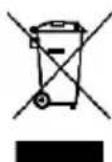
Should your machine need replacement after extended use, do not put it in the domestic waste but dispose of it in an environmentally safe way. Waste electrical products should not be disposed of with household waste. Please recycle where facilities exist. Check with your local Authority or retailer for recycling advice.
23 DECLARATION OF CONFORMITY


VARO N.V. - Joseph Van Instraat 9 - BE2500 Lier - BELGIUM, declares that,
product : Plunge Saw 1200 W
trade mark : POWERplus
model : POWX0561
is in conformity with the essential requirements and other relevant provisions of the applicable European Directives, based on the application of European harmonized standards. Any unauthorized modification of the apparatus voids this declaration.
European Directives (including, if applicable, their amendments up to the date of signature);
2011/65/EU
2014/30/EU
2006/42/EC
European harmonized standards (including, if applicable, their amendments up to the date of signature);
EN60745-1:2009
EN60745-2-5:2010
EN55014-1:2006
EN55014-2:1997
EN61000-3-2:2014
EN61000-3-3 : 2013
Keeper of the Technical Documentation : Philippe Vankerkhove, VARO – Vic. Van Rompuy N.V.
The undersigned acts on behalf of the company CEO,

Philippe Vankerkhove
Regulatory Affairs – Compliance Manager
Date : 01/09/2016

- POWERPLUS® HIGH QUALITY TOOLS
- POWX0561 EN
- PLUNGE SAW 1200W POWX0560
- APPLICATION
- DESCRIPTION (FIG. A)
- PACKAGE CONTENT LIST
- SYMBOLS
- GENERAL POWER TOOL SAFETY WARNINGS
- Work area
- Electrical safety
- Personal safety
- Power tool use and care
- Service
- ADDITIONAL SAFETY INSTRUCTIONS FOR PLUNGE SAWS
- CAUSES AND PREVENTION OF KICKBACK
- ADJUSTMENTS
- Plunge saw feature
- Selector switch
- Guide rails and clamps (Fig. 1)
- PREPARATION
- Mounting the plunge saw on the guide rail
- OPERATION
- Switching ON/OFF
- Setting the cutting depth
- (Fig 2)
- Setting the cutting angle (Fig. 4)
- Determine Cutting line (Fig. 5)
- Straight cuts (90° cut)
- Miter cuts (up to 48°) (Fig. 6)
- Marked cutting
- Plunge cuts
- Replacing the saw blade
- Before any maintenance work always switch off the plunge saw and disconnect from mains power.
- FINE ADJUSTMENT OF PLUNGE SAW PLAY ON GUIDE RAIL
- CONNECTING RODS FOR GUIDE RAILS (FIG. 7)
- GUIDE RAIL SPLINTER GUARDS (FIG. 8)
- KICKBACK STOP
- PLUNGE CUT WITH GUIDE RAIL
- CLEANING AND MAINTENANCE
- Cleaning
- Checking and replacing the carbon brushes
- Lubrication
- NOISE
- SERVICE DEPARTMENT
- STORAGE
- WARRANTY
- ENVIRONMENT
- DECLARATION OF CONFORMITY
Brand : VARO
Model : POWX0561
Category : Saw