
F-1300WTWP - Loudspeaker TOA - Free user manual and instructions
Find the device manual for free F-1300WTWP TOA in PDF.


| Product Type | Passive Speaker |
| Brand | TOA |
| Model | F-1300WTWP |
| Color | White |
| Enclosure Material | ABS Plastic |
| Speaker Type | 2-Way Bass Reflex |
| Woofer Size | 13 cm (5.1 inches) |
| Tweeter Size | 2.5 cm (1 inch) Dome |
| Power Handling (RMS) | 60 W |
| Power Handling (Peak) | 120 W |
| Impedance | 8 Ohms |
| Frequency Response | 80 Hz - 20 kHz |
| Sensitivity | 90 dB (1 W/1 m) |
| Dimensions (H x W x D) | 400 x 250 x 220 mm |
| Weight | 5.5 kg |
| Installation | Wall-mountable with included bracket |
| Input Connection | Screw terminals |
| Protection | Overload protection circuit |
| Weather Resistance | IP54 (splash-proof) |
| Safety Compliance | CE, RoHS |
| Maintenance | Clean with dry cloth |
| Spare Parts Availability | From authorized TOA distributors |
Frequently Asked Questions - F-1300WTWP TOA
User questions about F-1300WTWP TOA
0 question about this device. Answer the ones you know or ask your own.
Ask a new question about this device
Download the instructions for your Loudspeaker in PDF format for free! Find your manual F-1300WTWP - TOA and take your electronic device back in hand. On this page are published all the documents necessary for the use of your device. F-1300WTWP by TOA.
USER MANUAL F-1300WTWP TOA
natural_image
Line drawing of a 3D cube with visible edges and a small square symbol on the front face (no text or labels)Thank you for purchasing TOA's Speaker System.
Please carefully follow the instructions in this manual to ensure long, trouble-free use of your equipment.
TABLE OF CONTENTS
- SAFETY PRECAUTIONS .... 3
- GENERAL DESCRIPTION ...... 4
- FEATURES 4
- DIMENSIONAL DIAGRAM 4
- IMPEDANCE CHANGE
(F-1300BT, F-1300BTWP, F-1300WT, and F-1300WTWP only)....5
- ABOUT THE INPUT OVERLOAD PROTECTION CIRCUITRY
(F-1300B, F-1300W, F-1300BT, and F-1300WT only) 5
- NOTES ON OUTDOOR INSTALLATION
(F-1300BTWP and F-1300WTWP only) 6
- INSTALLATION
8.1. Using the Supplied Brackets
8.1.1. When using only the supplied brackets 7
8.1.2. When using both the supplied and optional mounting brackets ..... 7
8.2. Speaker Cable Connections ...... 7
8.3. Wall Mounting 8
8.4. Ceiling Mounting 10
8.5. Speaker Stand Mounting 12
8.6. Pole Mounting (F-1300BTWP and F-1300WTWP only) 13
8.7. Partition Board Mounting
(F-1300B, F-1300BT, F-1300W, and F-1300WT only) 14
-
REPAINTING THE SPEAKER 15
-
SPECIFICATIONS
10.1.F-1300B and F-1300W 16
10.2. F-1300BT and F-1300WT 17
10.3. F-1300BTWP and F-1300WTWP 18
1. SAFETY PRECAUTIONS
- Before installation or use, be sure to carefully read all the instructions in this section for correct and safe operation.
- Be sure to follow all the precautionary instructions in this section, which contain important warnings and/or cautions regarding safety.
• After reading, keep this manual handy for future reference.
Safety Symbol and Message Conventions
Safety symbols and messages described below are used in this manual to prevent bodily injury and property damage which could result from mishandling. Before operating your product, read this manual first and understand the safety symbols and messages so you are thoroughly aware of the potential safety hazards.

WARNING
Indicates a potentially hazardous situation which, if mishandled, could result in death or serious personal injury.
When Installing the Unit
- Install the unit only in a location that can structurally support the weight of the unit and the mounting bracket. Doing otherwise may result in the unit falling down and causing personal injury and/or property damage.
- Do not use other methods than specified to mount the bracket. Extreme force is applied to the unit and the unit could fall off, possibly resulting in personal injuries.
- Use nuts and bolts that are appropriate for the ceiling's or wall's structure and composition. Failure to do so may cause the speaker to fall, resulting in material damage and possible personal injury.
- Tighten each nut and bolt securely. Ensure that the bracket has no loose joints after installation to prevent accidents that could result in personal injury.
- Do not mount the unit in locations exposed to constant vibration. The mounting bracket can be damaged by excessive vibration, potentially causing the unit to fall, which could result in personal injury.
• (F-1300B, F-1300BT, F-1300W, and F-1300WT only)
Since the unit is designed for in-door use, do not install it outdoors. If installed outdoors, the aging of parts causes the unit to fall off, resulting in personal injury. Also, when it gets wet with rain, there is a danger of electric shock.
• (F-1300BTWP and F-1300WTWP only)
When installing the unit in the snowy area, take appropriate measures to prevent snow from lying on the unit. If the snow lies on the unit, the unit may fall, causing personal injuries. - Do not use anti-rust lubricant. If it contacts resin or rubber parts, they could deteriorate and cause the unit to fall, possibly resulting in personal injury.
- Do not install the unit where it is likely to be corroded in such places as bath rooms, indoor
pools, or seaside. In such locations the bracket may be vulnerable to corrosion, eventually allowing the speaker to fall resulting in personal injury.

CAUTION
Indicates a potentially hazardous situation which, if mishandled, could result in moderate or minor personal injury, and/or property damage.
When Installing the Unit
• (F-1300BT and F-1300WT only)
Never set the impedance switch to the "8 Ω" position when connecting the unit to the amplifier's high-impedance speaker line (70 V or 100 V line), as doing so may damage the unit or amplifier.
Be sure to set the switch to the "8 Ω" position when connecting to the amplifier's low-impedance line.
• (F-1300BT, F-1300BTWP, F-1300WT, and F-1300WTWP only)
Never set the impedance switch to the "170 Ω" position when operating the unit on 100 V line.
Failure to follow this instruction could result in damage to the unit or amplifier.
- Avoid touching the unit's sharp metal edge to prevent injury.
- To avoid electric shocks, be sure to switch off the amplifier's power when connecting the speakers.
When the Unit is in Use
- Do not place heavy objects on the unit as this may cause it to fall or break which may result in personal injury and/or property damage. In addition, the object itself may fall off and cause injury and/or damage.
- Do not operate the unit for an extended period of time with the sound distorting. This is an indication of a malfunction, which in turn can cause heat to generate and result in a fire.
- Do not stand or sit on, nor hang down from the unit as this may cause it to fall down or drop, resulting in personal injury and/or property damage.
- Have the unit checked periodically by the shop from where it was purchased. Failure to do so may result in corrosion or damage to the unit or its mounting bracket that could cause the unit to fall, possibly causing personal injury.
2. GENERAL DESCRIPTION
TOA's F-1300 Series Speakers are compact two-way speaker systems designed for high efficiency, wide range, and high power input handling capability. These speaker systems can be installed and used in many different applications with combined use of the supplied accessories and/or the optional mounting brackets.
3. FEATURES
- 110^ horizontal x 100^ vertical wide directivity high-frequency horn.
- Supplied bracket permits mounting to a wall, ceiling, or an optional speaker stand.
- Combined use of the supplied bracket and optional mounting bracket allows the speakers to be mounted in many different applications, including pole mounting ^1 , clusters, horizontal ceiling mounting ^2 , and partition board mounting ^*2 .
- Both the F-1300BTWP and F-1300WTWP feature a waterproof design (IPX4 standard) for protection from any adverse effects of outdoor installations.
- A rear-mounted rotary switch allows for speaker impedance selection of low impedance or high impedance ^*3 .
*1 Applies to the F-1300BTWP and F-1300WTWP.
*2 Applies to the F-1300B, F-1300BT, F-1300W, and F-1300WT.
*3 Applies to the F-1300BT and F-1300WT.
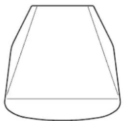
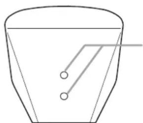
4. DIMENSIONAL DIAGRAM
Unit: mm (inches)
[Top]
natural_image
Simple line drawing of a frustum or truncated cone shape (no text or symbols)[Bottom]
natural_image
Simple line drawing of a teacup with two circular holes and a handle (no text or symbols)Mounting holes
Note
Hole seals are adhered over the holes at the factory. Before attaching the speaker mounting bracket to this side, remove them using a pointed tool.
[Front]
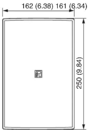
[Side] [Rear]
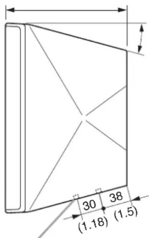
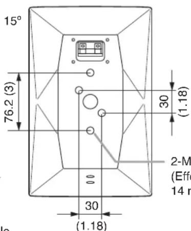
2-M5 mounting screw hole
(Effective screw depth: 14 mm or 0.55")
2-M5 mounting screw hole (Effective screw depth: 14 mm or 0.55")
5. IMPEDANCE CHANGE (F-1300BT, F-1300BTWP, F-1300WT, and F-1300WTWP only)
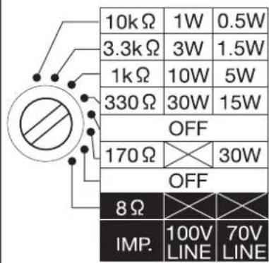
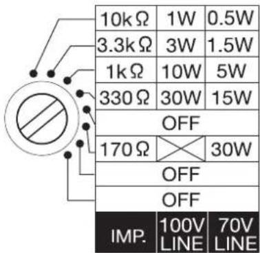
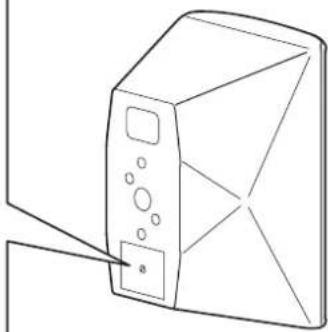
To change the impedance, use a standard screwdriver to rotate the rotary switch on the speaker's rear to select the desired input power.
Note: The switch is factory-preset to 330 Ω.
[F-1300BT and F-1300WT] [F-1300BTWP and F-1300WTWP]
natural_image
Line drawing of a computer monitor with a labeled control panel (no text or symbols present)
CAUTION
- Never set the rotary switch to the "8 Ω" position when connecting the F-1300BT or F-1300WT to the amplifier's high-impedance speaker line (70 V or 100 V line), as doing so may damage the speaker or amplifier.
Be sure to set this switch to the "8 Ω" position when connecting to the amplifier's low-impedance line. (F-1300BT and F-1300WT only)
- Never set this switch to the "170 Ω" position when operating the speaker on 100 V line. Failure to follow this instruction could result in damage to the speaker or amplifier.
6. ABOUT THE INPUT OVERLOAD PROTECTION CIRCUITRY
(F-1300B, F-1300W, F-1300BT, and F-1300WT only)
The speaker system features internal input overload protection circuitry for both high and low frequencies. If an excessive input level is fed to the unit, the protection circuitry automatically cuts off the signal to the speaker driver.
A drastic reduction in sound volume for the high or low frequency range indicates that the protection circuitry has been enabled.
In such cases, simply reduce the amplifier volume. The protection circuitry will automatically reset in approximately 10 seconds. After reset, maintain the volume at a level slightly lower than before.
Note
This protection circuitry does not completely protect the unit against input overload. Depending on the type or duration of excessive power input, the protection circuitry might not be enabled, resulting in damage to the speaker driver. Also, if the excessive power input continues for a long period of time, the circuitry may not be capable of resetting to its original condition.
Take care so that the speakers are not exposed to excessive power input.
7. NOTES ON OUTDOOR INSTALLATION (F-1300BTWP and F-1300WTWP only)
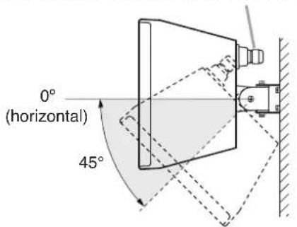
- Be sure to mount the speaker in a vertical (portrait-style) orientation.
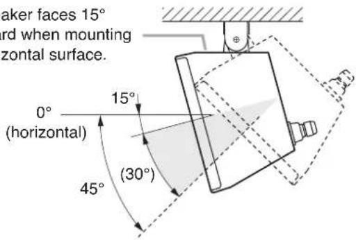
- Adjust the speaker's tilt angle within the shaded range shown below.
[Wall and pole: 0° horizontal to 45° downward] [Under eaves: 15° downward to 45° downward]
Note
Mount the speaker so that its rear-mounted terminal cover is positioned on the upper side.
Note
The speaker faces 15^ downward when mounting to a horizontal surface.
- Install the speaker in locations exposed to an ambient temperature range of -10^ to +50^ (14°F to 122°F). Exceeding this range could cause speaker failure.
- Use the supplied terminal cover when connecting the speaker cable.
[Terminal Cover Use]
![1 Speaker cable 2 Terminal cover (accessory) 3 Tapping screw 4 x 12 (accessory) 4 Bushing* Input terminal [Stripped conductor] 10 mm (0.39") 30 mm (1.18") Speaker unit * Screwed onto the Terminal cover at the factory.](/content/2026/05/1002670/images/c9d6d39d84f6e6e69dd8ca4568d2606ebee4732fa74ae20b3ccb4e37d2bcb0af.jpg)
Notes
- For the speaker cable, use a cable with a diameter of 6 - 10 mm (0.24 - 0.39"), which will fit the cable bushing.
• To ensure waterproof capabilities, firmly mount the terminal cover to the speaker and tighten the bushing on the cover.
Step 1. Feed the speaker cable through the bushing and terminal cover, then connect the cable to the input terminal.
Step 2. Attach the terminal cover to the speaker.
Attach the cover while pulling the cable so that it is not entangled inside the terminal cover.
Step 3. Hold the terminal cover tightly to the speaker using the supplied screws.
Step 4. Tighten the bushing.
Note
After tightening the bushing by hand, use a tool to further tighten it another 90^ (1/4-turn) or so. Note that parts can be damaged by over-tightening.
8. INSTALLATION
8.1. Using the Supplied Brackets
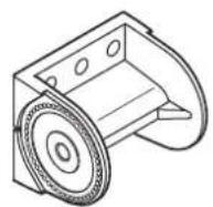
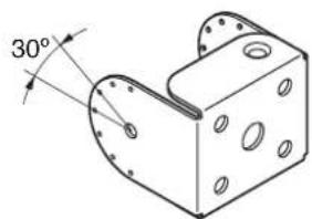
The speaker system is supplied with the following brackets. Use these brackets properly depending on the installation location and intended application.
[Wall bracket][Joint bracket][Speaker
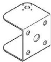
8.1.1. When using only the supplied brackets
| Installation Location | Application Wall bracket | Joint bracketSpeaker | bracket Page | ||
| Wall | When horizontal and vertical angle adjustability is desired. | √ | √ | √ | P. 8 |
| When close wall surface mounting is desired*. | √ | √ | — | P. 9 | |
| Ceiling | Vertical speaker mounting* | √ | √ | — | P. 10 |
| Speaker Stand (Option) | Mounting to the optional ST-16A Speaker Stand | √ | √ | — | P. 12 |
* Speaker coverage angles can only be adjusted in the vertical direction.
8.1.2. When using both the supplied and optional mounting brackets
| Installation Location | Application Option | Wall bracket | Joint bracket | Speaker | bracket Page | ||
| Ceiling | Horizontal speaker mounting | HY-CM10B or HY-CM10W | √ | √ | — | P. 11 | |
| Suspended speaker cluster mounting* | HY-CL10B | √ | √ | — | P. 11 | ||
| Pole | Mounting to a pole | YS-60B | √ | √ | √ | P. 13 | |
| Partition board | Mounting to a partition board | HY-BH10B | √ | √ | — | P. 14 |
* Speaker coverage angles can only be adjusted in the vertical direction.
8.2. Speaker Cable Connections
[Input terminal polarity] [Stripped conductor of cable]
Sperker unit (rear)
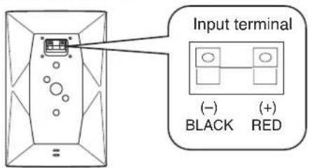
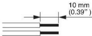
8.3. Wall Mounting
When adjusting horizontal and vertical angles:
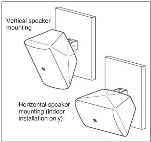
Use the supplied wall bracket, joint bracket, and speaker bracket to permit adjustment of the horizontal and vertical* speaker coverage angles.
* Vertical installation. Horizontal: Max. 75°, Vertical: Max. 45° downward Horizontal installation. Horizontal: Max. 49°, Vertical: Max. 45° downward
![[Wall bracket mounting dimensions] 4-ø6 mm (ø0.24") 30 mm (1.18") 30 mm (1.18") 2 Hexagon bolt M6 x 12 (with plain washer and spring washer) Joint bracket 4 Fixing bolt M5 x 60 6 Wall bracket 1 Installation example Vertical speaker mounting Horizontal speaker mounting (indoor installation only) Speaker unit Speaker bracket Speaker unit (rear) Speaker unit (rear) 3 [Vertical speaker installation] [Horizontal speaker installation] Speaker bracket Machine screw M5 x 20 (with plain washer and spring washer) Speaker unit (rear)](/content/2026/05/1002670/images/75566c839486c7cea5b937cee4e63c696614e8edc83fc57b88b2de0f928872eb.jpg)
Step 1. Mount the wall bracket to the wall surface. Match the orientation of the arrow label with the horizontal direction (left or right) the speaker faces. Note: Hardware used for mounting the wall bracket to the wall is not supplied.
- Arrow label orientation (Viewed from top of brackets)
![[Left-facing orientation] Arrow label Wall bracket Joint bracket](/content/2026/05/1002670/images/74da611603db0a3ef9a35bc730e86a289997cf02aadd01bc0f568eec91573bf4.jpg)
![[Right-facing orientation] Wall bracket Joint bracket Arrow label](/content/2026/05/1002670/images/8e53c407d4a2bf0329050879bffd21ebc2bfa28d26e0ab34e564ae5121e45d1d.jpg)
Step 2. Attach the joint bracket to the wall bracket using the supplied screws, adjust the horizontal speaker angle, then tighten the screws.
Note: Match the orientation of the arrows on both the wall bracket and joint bracket.
Step 3. Attach the speaker bracket to the speaker's rear using the supplied screws.
Note: Attach the speaker bracket according to the speaker mounting orientation.
Step 4. Mount the speaker to the joint bracket by inserting the speaker bracket into the joint bracket and loosely securing the fixing bolt for temporary speaker installation.
Step 5. Connect the speaker cable to the input terminal.
Note
Use a terminal cover when installing the speaker outdoors. (Refer to p.6 for terminal cover attachment.)
Step 6. Adjust the speaker's vertical mounting angle and tighten the fixing bolt.
The speaker angle is adjustable in 7.5° steps.
Note
The mating surfaces of the speaker bracket and joint bracket are designed to interlock. Ensure that both parts are securely engaged with each other after mounting is complete.
[Changing the orientation of the front panel logo]
The front panel logo is affixed to the mesh net using double-faced tape. Peel off the logo carefully and reaffix it in the proper orientation.
Mounting the speaker close to a wall surface
Use both the supplied joint bracket and speaker bracket, and mount the joint bracket directly to a wall. After mounting the joint bracket, follow the Steps 3 – 6 above. In this configuration, the speaker can only be adjusted in the vertical direction*.
* Vertical installation: Max. 30° downward, Horizontal installation: Max. 45° downward
Note: Hardware used for mounting the joint bracket to the wall is not supplied.
[Joint bracket mounting dimensions]
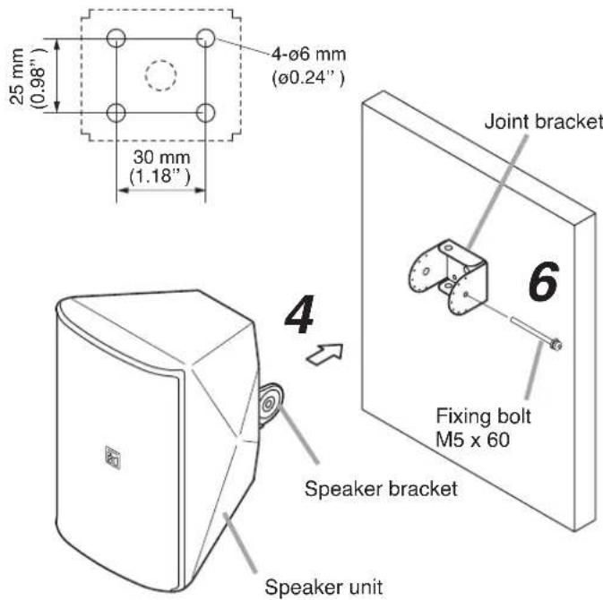
[Installation example]
8.4. Ceiling Mounting
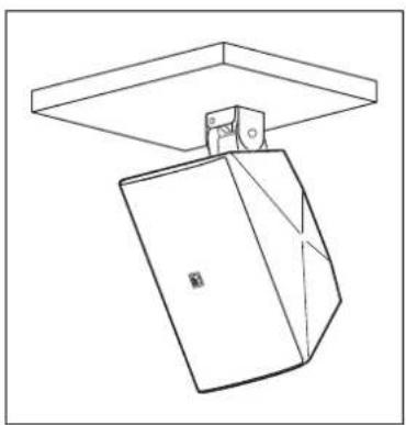
Vertical orientation
Use the supplied joint bracket and speaker bracket.
Note
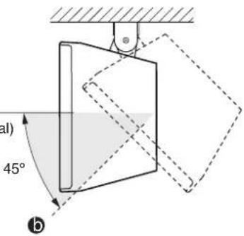
Speaker coverage angles can only be adjusted in the vertical direction (Max. 45° downward).
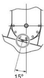
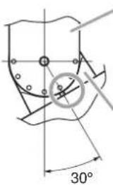
Adjust the speaker's tilt angle within the shaded range shown below.
![[Speaker angle vs. Bracket position] a 0° (horizontal) 45° downward Joint bracket a 0° (horizontal) Speaker bracket 15° 30° 45° b [Installation example]](/content/2026/05/1002670/images/763675a33c1d9085b09b149df37de34778178a00f6174eacc6894bb2555dd932.jpg)
natural_image
Pure technical line drawing of a mechanical component with no text or symbolsNotes
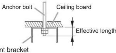
- Use an appropriate anchor bolt for supporting the full weight of the speaker and for the size of mounting hole in the joint bracket.
- Ensure that the effective length of the anchor bolt is 20 mm (0.79") or less.
- When speaker rotation capability is not desired, secure with the 4 fixed mounting screw holes.
1
Anchor bolt mounting hole
Joint bracket
Fixed mounting screw hole (4 holes)
Fixing bolt M5 x 60
2
Machine screw M5 x 20 (with plain washer and spring washer)
3
5
Speaker bracket
As hole seals are adhered over the holes, remove them using a pointed tool before attaching the bracket.
\* Changing the orientation of the front panel logo
The front panel logo is affixed to the mesh net using double-faced tape. Peel off the logo carefully and reaffix it in the proper orientation.
Front panel logo*
Speaker unit
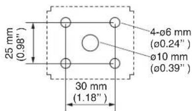
Step 1. Mount the joint bracket to the ceiling surface.
Note
Hardware used for mounting the joint bracket to the ceiling is not supplied.
Step 2. Attach the speaker bracket to the speaker's bottom using the supplied screws.
[Joint bracket mounting dimensions]
Step 3. Mount the speaker to the joint bracket by inserting the speaker bracket into the joint bracket and loosely securing the fixing bolt for temporary speaker installation.
Step 4. Connect the speaker cable to the input terminal.
Note
Use a terminal cover when installing the speaker outdoors. (Refer to p. 6 for terminal cover attachment.)
Step 5. Adjust the speaker's vertical mounting angle and tighten the fixing bolt.
The speaker angle is adjustable in 7.5° steps.
Note
The mating surfaces of the speaker bracket and joint bracket are designed to interlock. Ensure that both parts are securely engaged with each other after mounting is complete.
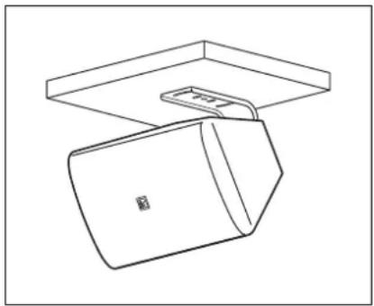
Horizontal orientation
(F-1300B, F-1300BT, F-1300W, and F-1300WT only)
Use the supplied joint bracket and speaker bracket in combination with the optional HY-CM10B or HY-CM10W Ceiling Mount Bracket.
Refer to the instruction manual enclosed with the optional mounting bracket for its mounting details.
[Installation example]
natural_image
Line drawing of a mechanical device with a rectangular housing and a flat top panel (no text or symbols)Cluster configuration assembly
(F-1300B, F-1300BT, F-1300W, and F-1300WT only)
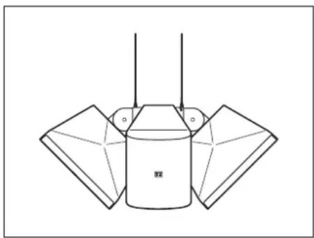
Use the supplied joint brackets and speaker brackets in combination with the optional HY-CL10B Cluster Bracket to permit a total of 4 speakers to be suspended from the ceiling as shown in the figure at right.
Refer to the instruction manual enclosed with the optional mounting bracket for its mounting details.
[Installation example]
natural_image
Pure technical line drawing of a mechanical component with no text or symbols8.5. Speaker Stand Mounting
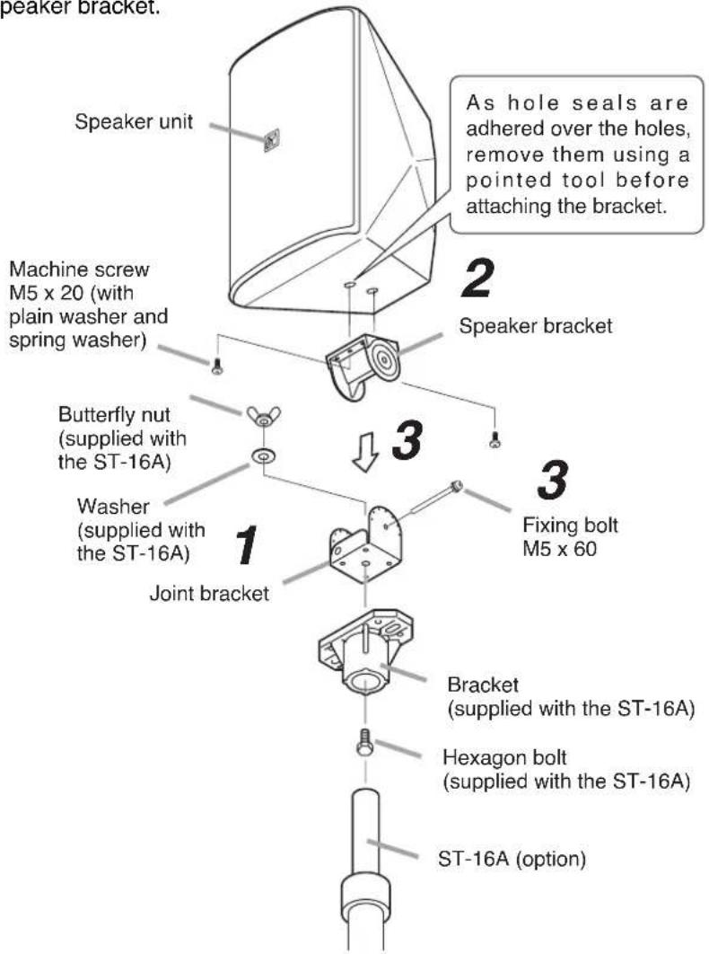
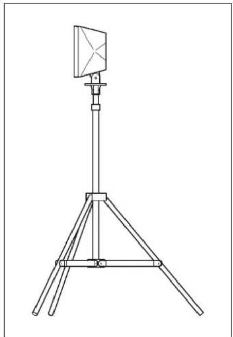
The speaker can be mounted on the optional ST-16A Speaker Stand using the supplied joint bracket and speaker bracket.
[Installation example]
natural_image
Line drawing of a tripod-mounted surveying instrument with a central dish (no text or symbols)Note
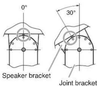
Mount the speaker so that it faces within the range of 15^ upward and downward.
Step 1. Attach the joint bracket to the speaker stand bracket using the speaker stand's supplied bolt and nut.
Step 2. Attach the speaker bracket to the speaker's bottom using the supplied screws.
Step 3. Mount the speaker to the joint bracket by inserting the speaker bracket into the joint bracket and loosely securing the fixing bolt for temporary speaker installation.
After adjusting the speaker's vertical mounting angle, tighten the fixing bolt.
The speaker angle is adjustable in 7.5° steps.
The mating surfaces of the speaker bracket and joint bracket are designed to interlock. Ensure that both parts are securely engaged with each other after mounting is complete.
![[Speaker angle vs. Bracket position] a 15° upward b 15° downward 0° Speaker bracket 30° Joint bracket](/content/2026/05/1002670/images/ebf452781663839dcd3a9f7899aa98e8407b4c824eecec25b1789ec8422bd90f.jpg)
Step 4. Connect the speaker cable to the input terminals.
Note
Use a terminal cover when installing the speaker outdoors. (Refer to p. 6 for terminal cover attachment.)
Note
For more information on mounting the bracket to the stand and stand usage, refer to the instruction manual enclosed with the ST-16A Speaker Stand.
8.6. Pole Mounting (F-1300BTWP and F-1300WTWP only)
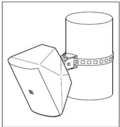
To mount the speaker on a pole with diameter of 10 - 34 cm (3.94 - 13.39"), use the supplied wall bracket, joint bracket, and speaker bracket in combination with the optional YS-60B Pole Band.
Speaker coverage angles can be adjusted in the horizontal and vertical direction*.
* Horizontal: Max. 90°, Vertical: Max. 45° downward
[Installation example]
natural_image
Line drawing of a cylindrical object with a flanged base and attached rectangular frame (no text or symbols)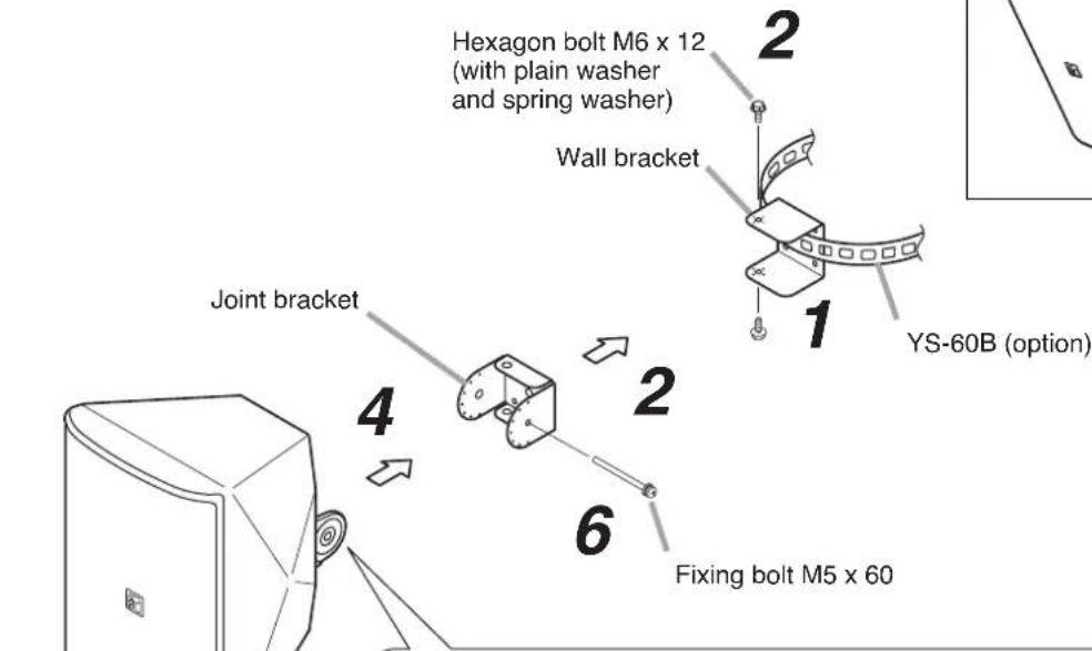
Speaker unit
3 [Speaker bracket mounting position]
Speaker bracket
Note
Set the
Note
Set the speaker in a vertical orientation, then attach the bracket so that the rear-mounted terminal cover is positioned above the mount.
Machine screw
M5 x 20 (with plain
washer and spring
washer)
Step 1. Attach the wall bracket to a pole using the YS-60B.
Match the orientation of the arrow label with the horizontal direction (left or right) the speaker faces.
- Arrow label orientation (Viewed from top of brackets)
![[Left-facing orientation] YS-60B YS-60B Wall bracket Joint bracket Arrow label [Right-facing orientation] Wall bracket Joint bracket Arrow label](/content/2026/05/1002670/images/1fdfcb7f233680838dd72eb1b92498b087db0a1b2f0d8ab606052c707644777c.jpg)
Step 2. Attach the joint bracket to the wall bracket using the supplied screws, adjust the horizontal speaker angle, then tighten the screws.
Note
Match the orientation of the arrows on both the wall bracket and joint bracket.
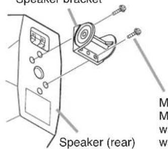
Step 3. Attach the speaker bracket to the speaker's rear using the supplied screws.
Note
Set the speaker in a vertical orientation, then attach the bracket so that the rear-mounted terminal cover is positioned above the mount.
Step 4. Mount the speaker to the joint bracket by inserting the speaker bracket into the joint bracket and loosely securing the fixing bolt for temporary speaker installation.
Step 5. Connect the speaker cable to the input terminal.
Note
Use a terminal cover when installing the speaker outdoors. (Refer to p. 6 for terminal cover attachment.)
Step 6. Adjust the speaker's vertical mounting angle and tighten the fixing bolt.
The speaker angle is adjustable in 7.5° steps.
Note
The mating surfaces of the speaker bracket and joint bracket are designed to interlock. Ensure that both parts are securely engaged with each other after mounting is complete.
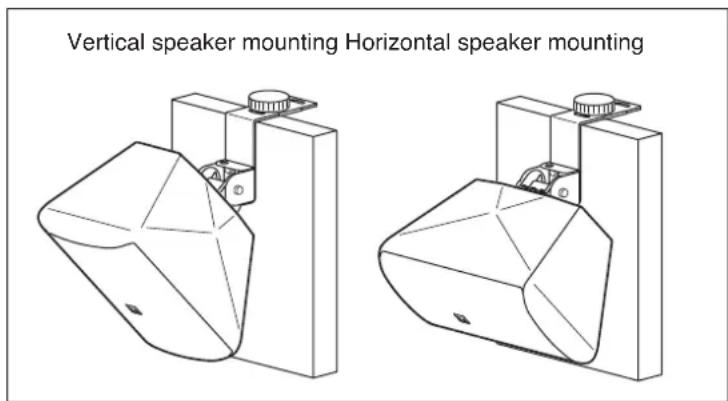
8.7. Partition Board Mounting (F-1300B, F-1300BT, F-1300W, and F-1300WT only)
Use the supplied joint bracket and speaker bracket in combination with the optional HY-BH10B Board Hanger Bracket.
Refer to the instruction manual enclosed with the optional mounting bracket for its mounting details.
[Installation example]
9. REPAINTING THE SPEAKER
Follow the procedure below when repainting the speaker grill and cabinet.
Note
Take care not to touch the speaker diaphragm during work.
Step 1. Peel off the logo carefully, then remove the screw underneath to detach the mesh speaker grill.
[Detaching the mesh grill]
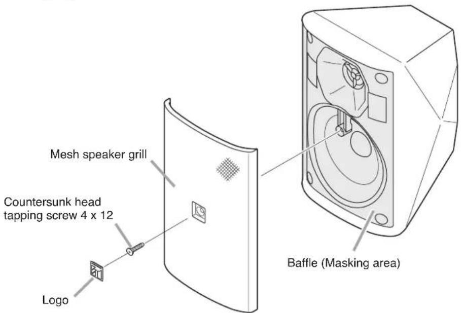
Note
Because the logo is affixed using double-faced tape, peel it off carefully.
Step 2. Wipe clean the mesh grill and speaker cabinet with a soft cloth dampened in a detergent.
Note
Do not use thinner or other volatile liquids to clean the grill and cabinet.
Step 3. Use spray paint to apply thin coat evenly overall the speaker.
Notes
- Avoid painting with a roller or brush, as the grill holes could become clogged with paint.
- Securely mask the entire baffle surface before painting.
- Use appropriate paints for the speaker grill and cabinet materials.
Grill: Rolled steel plate (acrylic paint)
Cabinet: HIPS resin
Step 4. After the paint has dried, apply another light coat.
Note
Repeating Step 3, apply 2 or more light coats of paint.
Application of one thick coat of paint all at once may cause drips or unevenness to show up in the painted finish, or clog the mesh holes.
Step 5. After the paint has dried, replace the mesh grill and logo.
10. SPECIFICATIONS
10.1. F-1300B and F-1300W
| Model No. | F-1300B F-1300W | |
| Enclosure Type | Bass-reflex type | |
| Power Handling Capacity | 50 W (continuous pink noise)150 W (continuous program) | |
| Rated Impedance | 8 Ω | |
| Output Sound Pressure Level | 90 dB (1 W, 1 m) at installation in a semianechoic field | |
| Frequency Response | 80 – 20,000 Hz, -10 dB at installation in a semianechoic field | |
| Crossover Frequency | 2 kHz | |
| Directivity Angle | Horizontal: 110°, Vertical: 100° | |
| Speakers | Woofer: 13 cm (5") cone-typeTweeter: 25 mm (1") dome tweeter | |
| Input Terminals | Push-in terminals | |
| Enclosure | HIPS, black HIPS, white | |
| Mesh Speaker Grill | Surface-treated steel plate, black, paint Surface-treated steel plate, white, paint | |
| Speaker Bracket | Aluminum die-cast, black, paint Aluminum die-cast, white, paint | |
| Joint Bracket, Wall Bracket | Steel plate, t1.6, black, paint Steel plate, t1.6, white, paint | |
| Dimensions | 162 (w) x 250 (h) x 161 (d) mm (6.38" x 9.84" x 6.34") | |
| Weight | 3.1 kg (6.83 lb) (including the supplied brackets) | |
| Accessories | Speaker bracket ... 1, Joint bracket ... 1, Wall bracket ... 1, Fixing bolt M5 x 60 ... 1,Hexagon bolt M6 x 12 (with plain washer and spring washer) ... 2,Machine screw M5 x 20 (with plain washer and spring washer) ... 2 | |
| Optional Products | Board hanger bracket: HY-BH10B BoardCeiling mount bracket: HY-CM10B Ceiling mount bracket: HY-CM10WCluster bracket: HY-CL10B Cluster bracket: HY-CL10BSpeaker stand: ST-16A Speaker stand: ST-16A | |
Note: The design and specifications are subject to change without notice for improvement.
10.2. F-1300BT and F-1300WT
| Model No. | F-1300BT F-1300WT | |
| Enclosure Type | Bass-reflex type | |
| Rated Input | 30 W (high impedance) | |
| Power Handling Capacity | Continuos pink noise: 50 W (low impedance)Continuos program: 150 W (low impedance) | |
| Rated Impedance | 8 Ω,100 V line: 330 Ω (30 W), 1 kΩ (10 W), 3.3 kΩ (3 W), 10 kΩ (1 W)70 V line: 170 Ω (30 W), 330 Ω (15 W), 1 kΩ (5 W), 3.3 kΩ (1.5 W), 10 kΩ (0.5 W) | |
| Output Sound Pressure Level | 90 dB (1 W, 1 m) at installation in a semianechoic field | |
| Frequency Response | 80 – 20,000 Hz, -10 dB at installation in a semianechoic field | |
| Crossover Frequency | 2 kHz | |
| Directivity Angle | Horizontal: 110°, Vertical: 100° | |
| Speakers | Woofer: 13 cm (5") cone-typeTweeter: 25 mm (1") dome tweeter | |
| Input Terminals | Push-in terminals | |
| Enclosure | HIPS, black HIPS, white | |
| Mesh Speaker Grill | Surface-treated steel plate, black, paint Surface-treated steel plate, white, paint | |
| Speaker Bracket | Aluminum die-cast, black, paint Aluminum die-cast, white, paint | |
| Joint Bracket, Wall Bracket | Steel plate, t1.6, black, paint Steel plate, t1.6, white, paint | |
| Dimensions | 162 (w) x 250 (h) x 161 (d) mm (6.38" x 9.84" x 6.34") | |
| Weight | 3.6 kg (7.94 lb) (including the supplied brackets) | |
| Accessories | Speaker bracket ... 1, Joint bracket ... 1, Wall bracket ... 1, Fixing bolt M5 x 60 ... 1,Hexagon bolt M6 x 12 (with plain washer and spring washer) ... 2,Machine screw M5 x 20 (with plain washer and spring washer) ... 2 | |
| Optional Products | Board hanger bracket: HY-BH10B BoardCeiling mount bracket: HY-CM10B Ceilingmount bracket: HY-CM10WCluster bracket: HY-CL10B Cluster bracket: HY-CL10BSpeaker stand: ST-16A | hanger bracket: HY-BH10BMount bracket: HY-CM10WSpeaker stand: ST-16A |
Note: The design and specifications are subject to change without notice for improvement.
10.3. F-1300BTWP and F-1300WTWP
| Model No. | F-1300BTWP F-1300WTWP | |
| Enclosure Type | Bass-reflex type | |
| Power Handling Capacity | 30 W | |
| Rated Impedance | 100 V line: 330 Ω (30 W), 1 kΩ (10 W), 3.3 kΩ (3 W), 10 kΩ (1 W)70 V line: 170 Ω (30 W), 330 Ω (15 W), 1 kΩ (5 W), 3.3 kΩ (1.5 W), 10 kΩ (0.5 W) | |
| Output Sound Pressure Level | 90 dB (1 W, 1 m) at installation in a semianechoic field | |
| Frequency Response | 80 – 20,000 Hz, -10 dB at installation in a semianechoic field | |
| Crossover Frequency | 2 kHz | |
| Directivity Angle | Horizontal: 110°, Vertical: 100° | |
| Speakers | Woofer: 13 cm (5") cone-typeTweeter: 25 mm (1") dome tweeter | |
| Input Terminals | Push-in terminals | |
| Water Resistance | IPX4 | |
| Operating Temperature | -10 °C to +50 °C (14°F to 122°F) | |
| Enclosure | HIPS, black HIPS, white | |
| Mesh Speaker Grill | Surface-treated steel plate, black, Surface-treated steel plate, white,anti-rust paint anti-rust paint | |
| Speaker Bracket | Aluminum die-cast, black, paint Aluminum die-cast, white, paint | |
| Joint Bracket, Wall Bracket | Stainless steel, t1.5 | |
| Dimensions | 162 (w) x 250 (h) x 161 (d) mm (6.38" x 9.84" x 6.34") | |
| Weight | 3.6 kg (7.94 lb) (including the supplied brackets) | |
| Accessories | Speaker bracket ... 1, Joint bracket ... 1, Wall bracket ... 1, Fixing bolt M5 x 60 ... 1,Hexagon bolt M6 x 12 (with plain washer and spring washer) ... 2,Machine screw M5 x 20 (with plain washer and spring washer) ... 2,Terminal cover ... 1, Tapping screw 4 x 12 ... 4 | |
| Optional Products | Pole band: YS-60B | |
Note: The design and specifications are subject to change without notice for improvement.
Traceability Information for Europe (EMC directive 2004/108/EC)
Manufacturer:
TOA Corporation
7-2-1, Minatojima Nakamachi, Chuo-ku, Kobe, Hyogo,
Japan
Authorized representative:
TOA Electronics Europe GmbH
Suederstrasse 282, 20537 Hamburg,
Germany

- TABLE OF CONTENTS
- SAFETY PRECAUTIONS
- Safety Symbol and Message Conventions
- WARNING
- When Installing the Unit
- CAUTION
- When the Unit is in Use
- GENERAL DESCRIPTION
- FEATURES
- DIMENSIONAL DIAGRAM
- Note
- IMPEDANCE CHANGE (F-1300BT, F-1300BTWP, F-1300WT, and F-1300WTWP only)
- ABOUT THE INPUT OVERLOAD PROTECTION CIRCUITRY
- NOTES ON OUTDOOR INSTALLATION (F-1300BTWP and F-1300WTWP only)
- Notes
- INSTALLATION
- Using the Supplied Brackets
- When using only the supplied brackets
- When using both the supplied and optional mounting brackets
- Speaker Cable Connections
- [Input terminal polarity] [Stripped conductor of cable]
- Wall Mounting
- [Changing the orientation of the front panel logo]
- Mounting the speaker close to a wall surface
- Ceiling Mounting
- Vertical orientation
- 1
- 2
- 3
- 5
- \* Changing the orientation of the front panel logo
- Horizontal orientation
- (F-1300B, F-1300BT, F-1300W, and F-1300WT only)
- Cluster configuration assembly
- Speaker Stand Mounting
- Pole Mounting (F-1300BTWP and F-1300WTWP only)
- Partition Board Mounting (F-1300B, F-1300BT, F-1300W, and F-1300WT only)
- REPAINTING THE SPEAKER
- [Detaching the mesh grill]
- SPECIFICATIONS
- F-1300B and F-1300W
- F-1300BT and F-1300WT
- F-1300BTWP and F-1300WTWP
- Traceability Information for Europe (EMC directive 2004/108/EC)
Brand : TOA
Model : F-1300WTWP
Category : Loudspeaker