
VNT832 - Router VTECH - Free user manual and instructions
Find the device manual for free VNT832 VTECH in PDF.


| Brand | VTech |
| Model | VNT832 |
| Product Type | 4-Port Ethernet Router |
| Power Supply | Input: 100-240V AC, 500mA, 50/60Hz; Output: 12V DC, 1000mA |
| Network Interfaces | 4x LAN 10/100 Mbps RJ-45, 1x WAN 10/100 Mbps RJ-45, 1x USB 2.0 |
| Wireless Standard | IEEE 802.11 b/g/n |
| Frequency Band | 2.4 GHz |
| LED Indicators | Power, Wi-Fi, WAN, LAN, USB, WPS |
| Security Features | WPA2, WPA, WEP, MAC filter, IP/Port filter, URL filter, DoS protection, DMZ, VPN pass-through |
| Management | Web-based GUI (HTTP), Telnet, UPnP, SNTP, Dynamic DNS, Firmware upgrade via HTTP |
| USB Port | File sharing via FTP |
| Operating Temperature | 34°F to 104°F (0°C to 40°C) |
| Weight (estimated) | ~300 g |
| Dimensions (estimated) | ~190 x 120 x 30 mm |
| Warranty | 2 years limited |
| Compliance | FCC Part 15 Class B, CAN ICES-3 (B)/NMB-3(B), cETL |
Frequently Asked Questions - VNT832 VTECH
User questions about VNT832 VTECH
0 question about this device. Answer the ones you know or ask your own.
Ask a new question about this device
Download the instructions for your Router in PDF format for free! Find your manual VNT832 - VTECH and take your electronic device back in hand. On this page are published all the documents necessary for the use of your device. VNT832 by VTECH.
USER MANUAL VNT832 VTECH
businessphones.vtech.com
to register your product forenhanced warranty support andthe latest VTech product news.
4-Port Ethernet Router
vtech®
User's manual
Congratulations
on your purchase of this VTech product. Before using this product, please read the Important safety information.
This user's manual provides you with the complete installation, setup and operation instructions.
For customer service or product information, visit our website at businessphones.vtech.com or call 1 (888) 370-2006.
Model number: VNT832
Type: 4-Port Ethernet Router
Serial number: ____
Purchase date: ____
Place of purchase: ____
Both the model and serial numbers of your VTech product can be found on the bottom of the router.
Save your sales receipt and original packaging in case it is necessary to return your router for warranty service.
Important Safety Information
When using your equipment, basic safety precautions should always be followed to reduce the risk of fire, electric shock and injury, including the following:
- Read and understand all instructions.
- Do not use this product near water such as near a bath tub, wash bowl, kitchen sink, laundry tub or swimming pool, or in a wet basement or shower.
- Do not place this product on an unstable table, shelf, stand or other unstable surfaces.
- CAUTION: Use only the adapters included with this product. Incorrect adapter polarity or voltage can seriously damage the product. Power adapter: Input 100–240V AC 500mA 50/60Hz; Output: 12V DC 1000mA.
- The power adapters are intended to be correctly oriented in a vertical or floor mount position. The prongs are not designed to hold the plug in place if it is plugged into a ceiling, under-the-table or cabinet outlet.
- For pluggable equipment, the socket-outlet shall be installed near the equipment and shall be easily accessible.
- Unplug this product from the wall outlet before cleaning. Do not use liquid or aerosol cleaners. Use a damp cloth for cleaning.
- Do not cut off the power adapters to replace them with other plugs, as this causes a hazardous situation.
- Do not allow anything to rest on the power cords. Do not install this product where the cords may be walked on or crimped.
- This product should be operated only from the type of power source indicated on the marking label. If you are not sure of the type of power supplied at the premises, consult your dealer or local power company.
- Do not overload wall outlets or use an extension cord.
- This product should not be placed in any area where proper ventilation is not provided. Slots and openings in the back or bottom of this product are provided for ventilation. To protect them from overheating, these openings must not be blocked by placing the product on a soft surface such as a bed, sofa or rug. This product should never be placed near or over a radiator or heat register.
- Never push objects of any kind into this product through the slots because they may touch dangerous voltage points or create a short circuit. Never spill liquid of any kind on the product.
- To reduce the risk of electric shock, do not disassemble this product, but take it to an authorized service facility. Opening or removing parts of the product other than specified access doors may expose you to dangerous voltages or other risks. Incorrect reassembling can cause electric shock when the product is subsequently used.
- Periodically examine all components for damage.
SAVE THESE INSTRUCTIONS
Important Safety Information
Electromagnetic fields (EMF)
This VTech product complies with all standards regarding electromagnetic fields (EMF). If handled properly and according to the instructions in this user's manual, the product is safe to be used based on scientific evidence available today.
Parts checklist
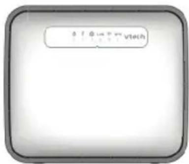
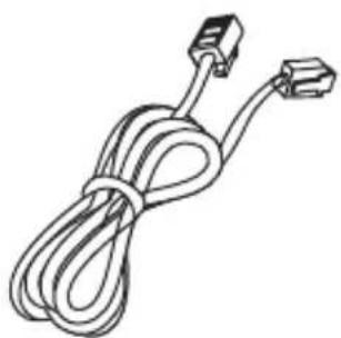
Your router package contains the following items. Save your sales receipt and original packaging in the event warranty service is necessary.
manual
RouterAbridged user's
natural_image
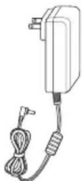
Line drawing of a coiled cable with connectors (no text or symbols)Ethernet cable Power adapter
natural_image
Line drawing of a handheld electric shock absorber with cable and plug (no text or symbols)Table of Contents
Important Safety Information ... i
Parts checklist......ii
Getting started ....3
Router Overview......3
Connect your system ....5
Configure your computer network .6
For Windows XP/2000......6
For Windows Vista/7/8......9
Connecting wireless devices.....12
Manual connection....12
Using WPS....12
Configure your router ......13
Log in to the web management
page 13
Web management page
overview ....14
Fast configuration .....15
Status....16
Device info: Wireless Router
Status 16
Statistics 17
Setup....18
WAN: WAN Configuration......18
LAN: LAN Interface Setup ..... 20
LAN: DHCP mode:....21
LAN: DHCP Static IP
Configuration......23
WLAN: Wireless Basic
Settings......24
WLAN: Wireless Security
Setup 25
WLAN: Wireless Multiple
BSSID Setup 27
WLAN: Wireless Access
Control....28
WLAN: Wireless Advanced
Settings......29
WLAN: Wi-Fi Protected Setup..31
WLAN: WDS Settings......32
Advanced....33
Route: Routing configuration .... 33
Route: RIP Configuration......34
NAT: DMZ 35
NAT: Virtual server......36
NAT: ALG 37
NAT: NAT port trigger 38
NAT: NAT IP mapping ...... 39
QoS: IP QoS....40
QoS: IP QoS traffic shaping:.....41
Port Mapping Configuration.....42
Others: Bridge Setting......43
Others: Client limit
configuration......44
Others: Telnet 44
Service 45
UPnP 45
DNS Configuration......46
Dynamic DNS Configuration..... 47
USB Storage 48
Firewall 49
MAC filter....49
IP/Port filter....50
URL filter....52
DoS....53
Maintenance ....54
Update: Upgrade firmware ..... 54
Update: Backup/restore settings: 56
Password: User account configuration....58
Reboot....60
Time....61
Log: Log setting......62
Diagnostics: Ping 62
Diagnostics: Traceroute ...... 63
Diagnostics: Diagnostic test.....64
Appendix......65
Frequently asked questions......65
FCC part 15 ......66
For cETL compliance only ......67
For cETL compliance only ......68
Limited Warranty......69
Technical specifications....71
Getting started Router Overview
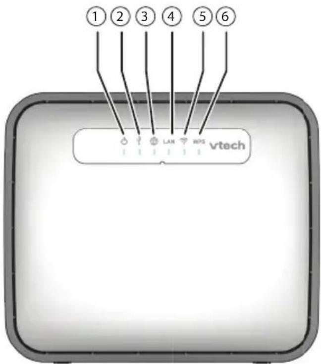
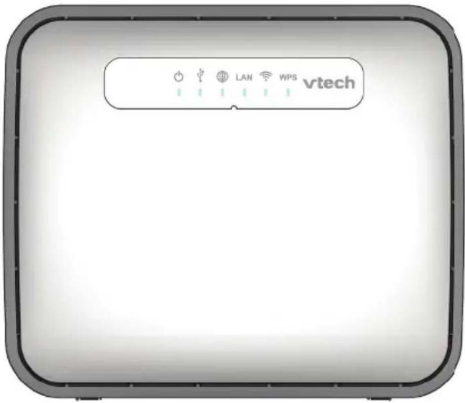
1- On/Off light
- On when the router is powered on.
2- USB light
- On when there is a device connected to the USB port.
• Flashes when the USB port receives data - Off when no device is connected to the USB port.
3- WAN light
- On when the Internet connectivity is established as the WAN port is connected to Internet.
4- Light
- On when any LAN port is connected.
- Flashes when any LAN port receives data.
5- Wi-Fi light
- On when the Wi-Fi is turned on.
- Off when the Wi-Fi is turned off.
6- light
- On when WPS is in progress.
- Off when the WPS is not in progress.
Getting started
Router Overview
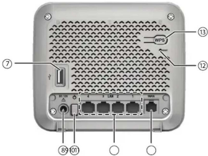
7-USB port
- Connects to USB device for file sharing.
8-Power jack
- Connects to the power adapter.
9- On/Off button
- Press to power on the router.
- Press once again to power it off.
10-LAN ports
- Connect to Ethernet devices such as computers and SIP phones.
11-WAN port
- Connects to the wide area network.
12-RESET button
- Press and hold (using a narrow-pointed object) to reset the router to default settings.
13-WPS button
• After turning on the Wi-Fi, press and hold for 10 seconds to start the Wireless Protected Setup (WPS).
Getting started
Connect your system
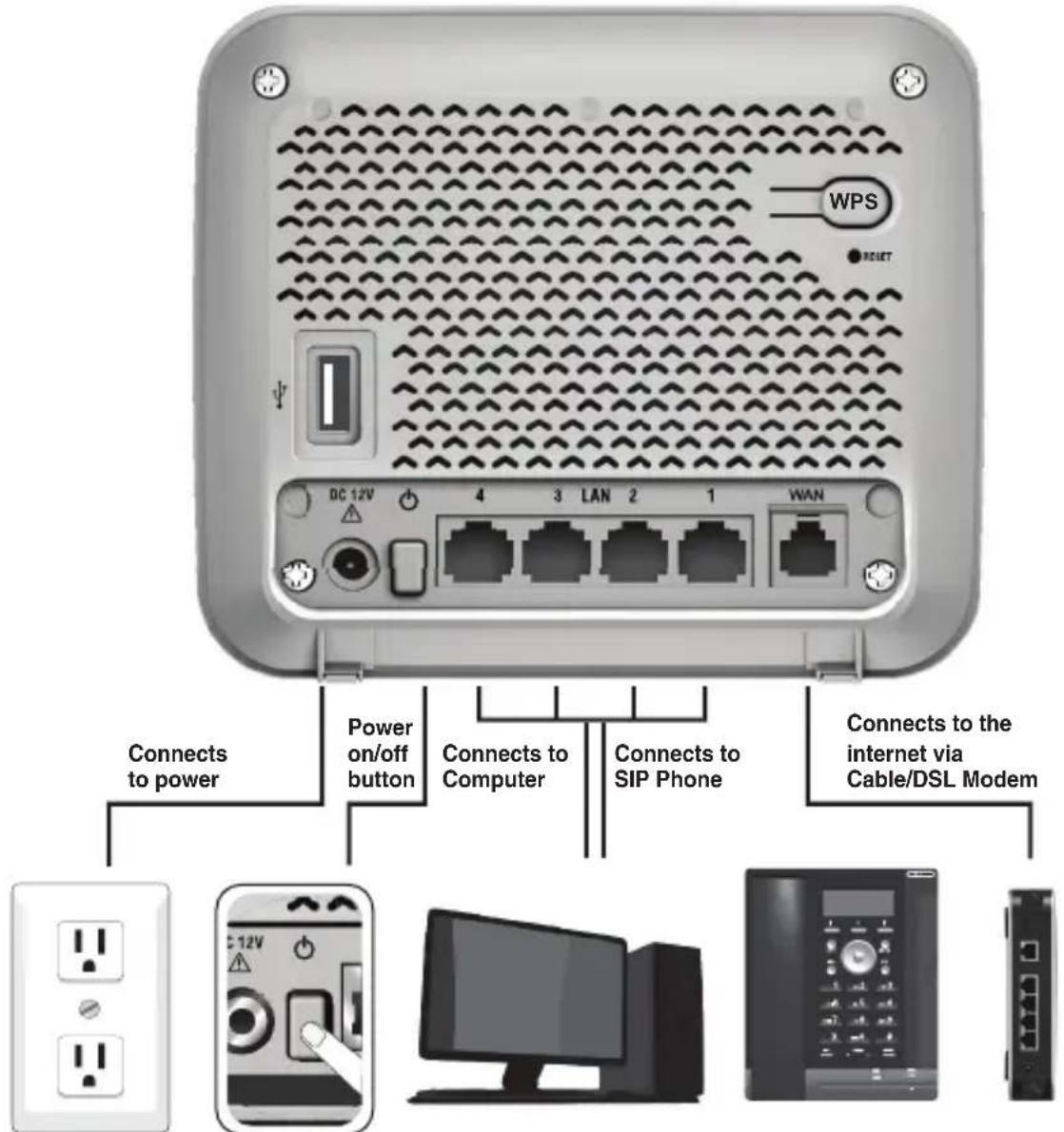
The VNT832 router has four LAN ports for connecting Ethernet devices such as computers and SIP phones. Before you start setting up your system, plan it carefully. Consider the number of Ethernet device(s) you need to connect before you start planning your system.
NOTES
• Use only the adapter provided.
• Make sure the electrical outlet is not controlled by a wall switch.
- The adapter is intended to be correctly oriented in a vertical or floor mount position. The prongs are not designed to hold the plug in place if it is plugged into a ceiling, under-the-table or cabinet outlet.
To power on, press the ⏻ button at the back of the router. The ⏻ light will turn on.
Getting Started
Configure your computer network
In order to view or change the settings of the VNT832 router, you need to login to the web management page of the router. Before that, connect your computer to the LAN port of the router, and then set the computer to obtain IP address automatically according to the steps below.
For Windows XP/2000
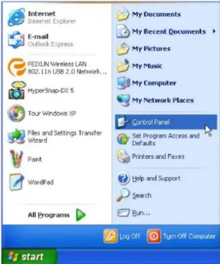
- Click Start, then open the Control Panel.
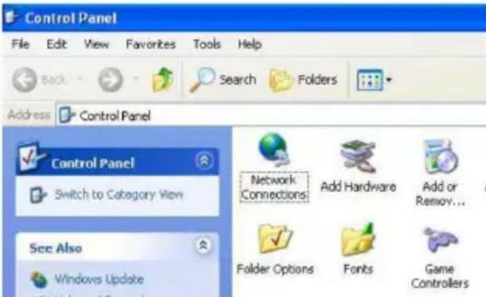
- Double-click Network Connections.
Getting Started
Configure your computer network
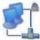
- Right-click Local Area Connection, and then select Properties.
LAN or High-Speed Internet
Local Area Connection
Connected, Firewalled
AMD PCNET Fa
Disable
Status
Repair
Bridge Connections
Create Shortcut
Delete
Rename
Properties

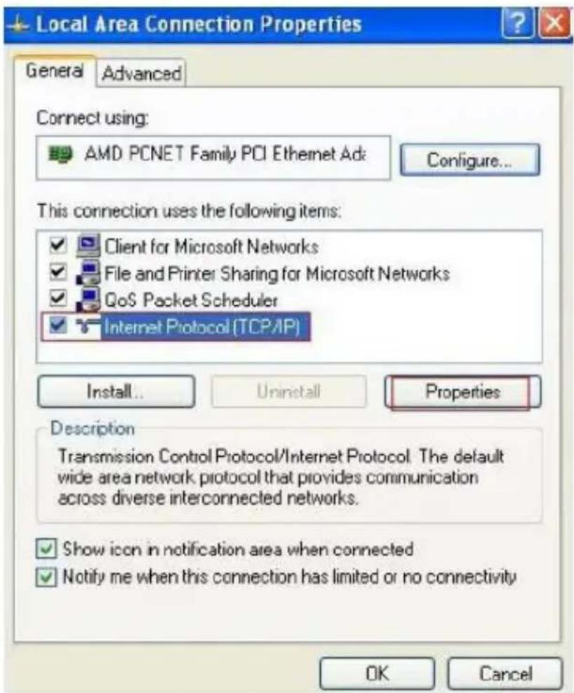
- Select Internet Protocol (TCP/IP), and then click Properties.
Getting Started
Configure your computer network
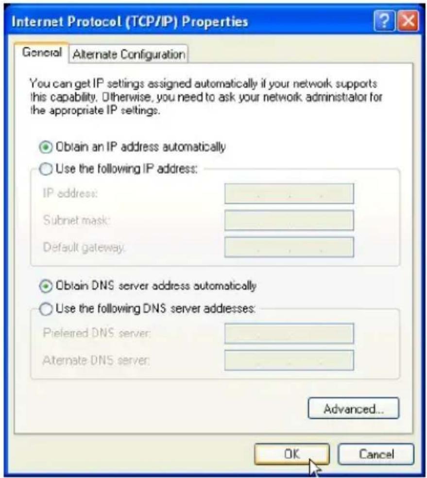
5. Select Obtain IP address automatically and Obtain DNS server address automatically, and then click OK.
Getting Started
Configure your computer network
For Windows Vista/7/8
- Click Start, and then open the Control Panel.
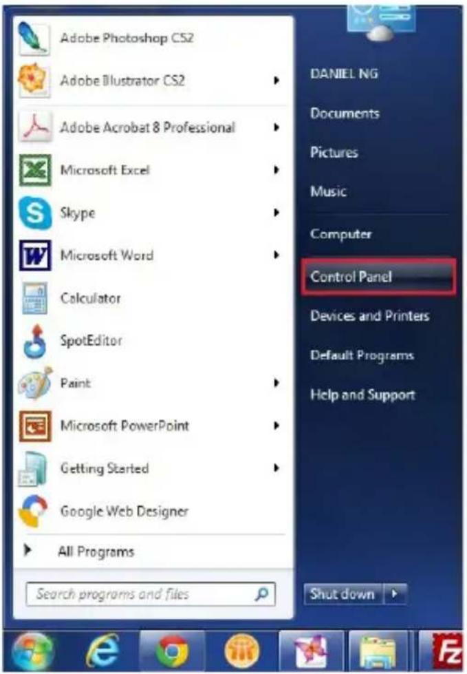
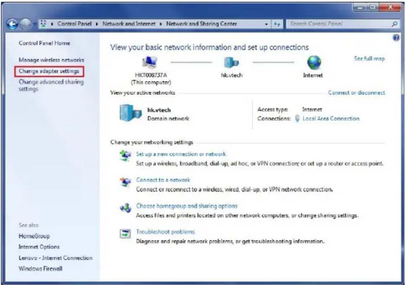
- Click Network and Internet, and then Network and Sharing Center.

Getting Started
Configure your computer network
3. Click Change adapter settings.
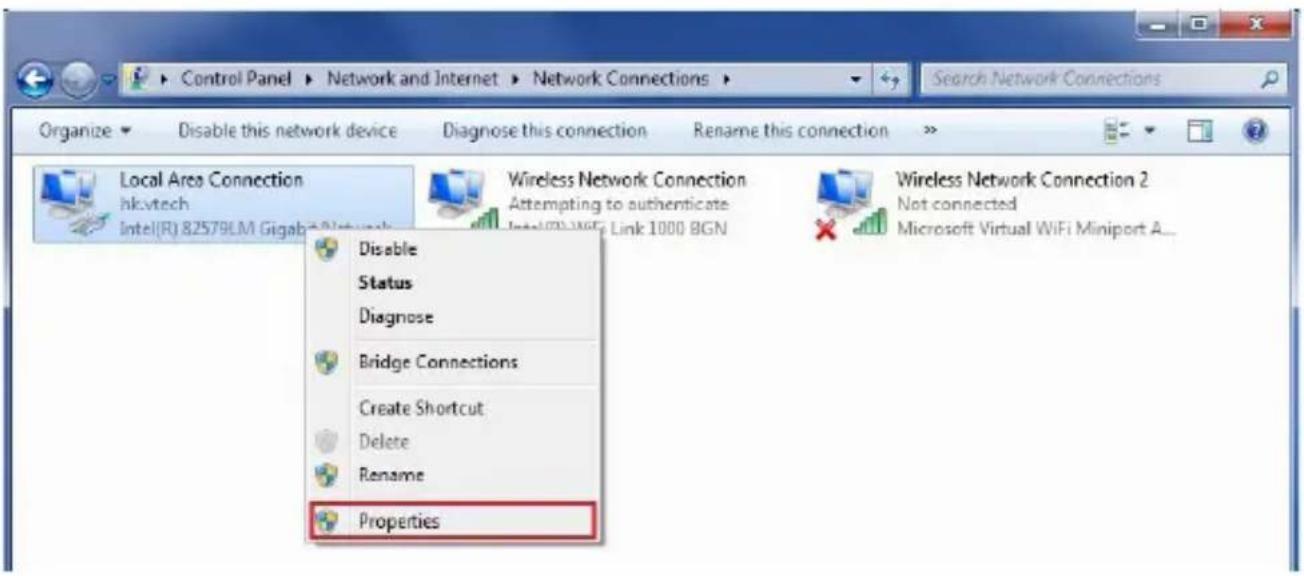
4. Right-click Local Area Connection, and then select Properties.
Getting Started
Configure your computer network
5. Select Internet Protocol Version 4 (TCP/IPv4), and then click Properties.
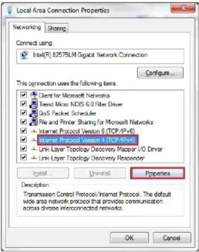
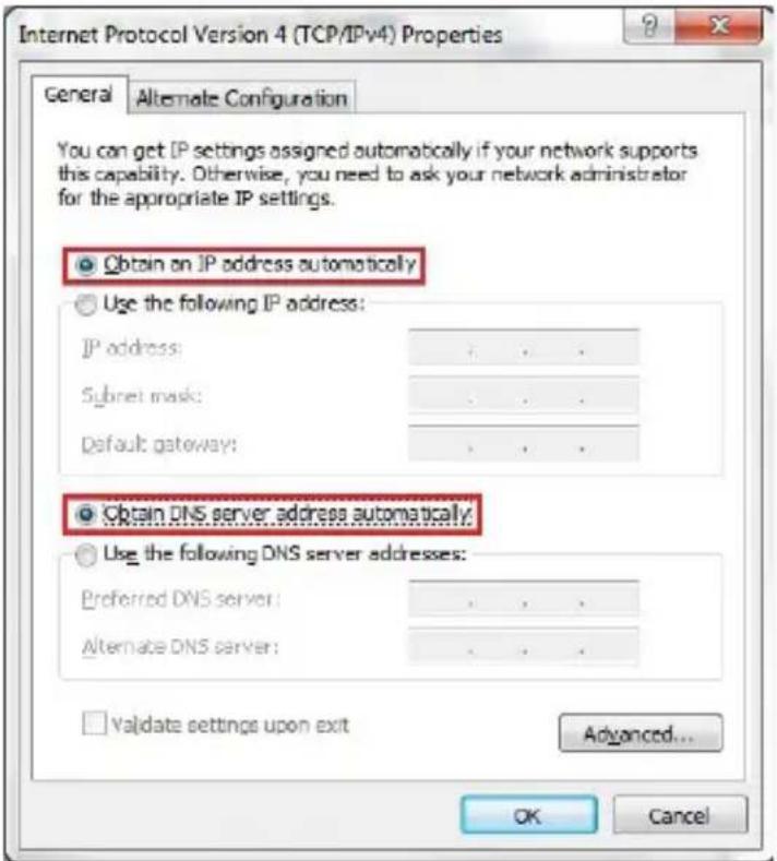
6. Select Obtain an IP address automatically and Obtain DNS server address automatically, and then click OK.
Getting Started
Connecting wireless devices
Before you connect wireless devices to the router, you should run the fast configuration Wizard. See “Fast configuration” on page 15.
You can connect wireless devices manually or by using WPS, which is fast and convenient.
Manual connection
- On your wireless device, open your Network or Wi-Fi settings and find the list of available Wi-Fi networks.
- Find the network name (SSID) for your VNT832 router. If you have trouble identifying the SSID, it is printed on the label on the bottom of the router.
- On your device, select the network and enter the Wi-Fi password, which is also printed on the label on the bottom of the router.
- On your device, click Connect.
Using WPS
-
On the router, press and hold the Wi-Fi/WPS button for 10 seconds.
The WPS light on the front panel turns on, and you will have two minutes to complete the rest of this procedure. -
On your device, find your WPS settings and turn WPS on.
Your device will connect to the network. If your device requests a WPS PIN, the WPS PIN is printed on the label on the bottom of the router.
To configure additional WPS settings for the router, see "WLAN: Wi-Fi Protected Setup" on page 31.
Configure your router
Log in to the web management page
With your computer connected to a LAN port of the router and set to obtain an IP address automatically, power on the router. You can log in to the web management page to browse the router settings and change them if necessary.

TIP
- Before you browse the web management page, check your browser's network setting. Make sure you do not use a proxy server for LAN setting.
- Open a web browser on your computer.
- Type http://192.168.1.1 in the address bar, and then press Enter. The following login page displays.
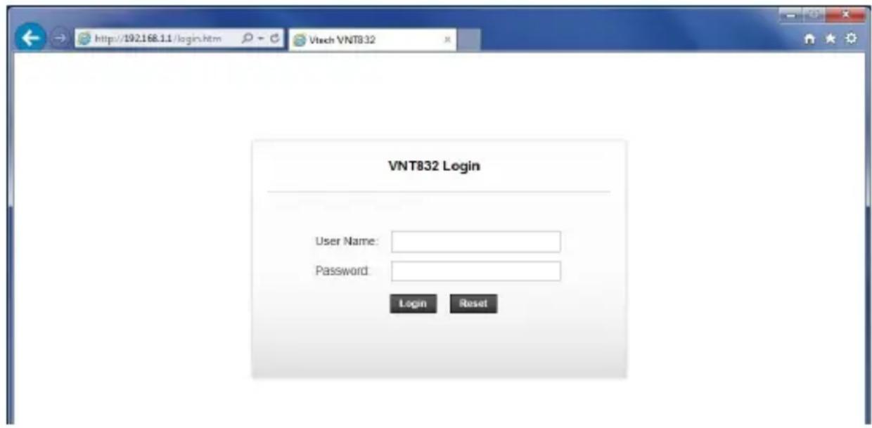
- Enter the default user name and password for the administrative account as shown below. The user name and password are case-sensitive.
Username: admin
Password: 12345
- Click Login to enter the web management page of the router.

NOTE
- Both administrative account and normal user account can view the router settings. To change the settings, you must login using an administrative account.
Configure your router
Web management page overview
After you logged in to the web management page, you can do the configurations of your router here. You will see the menus for Status, Wizard, Setup, Advanced, Service, Firewall, and Maintenance.
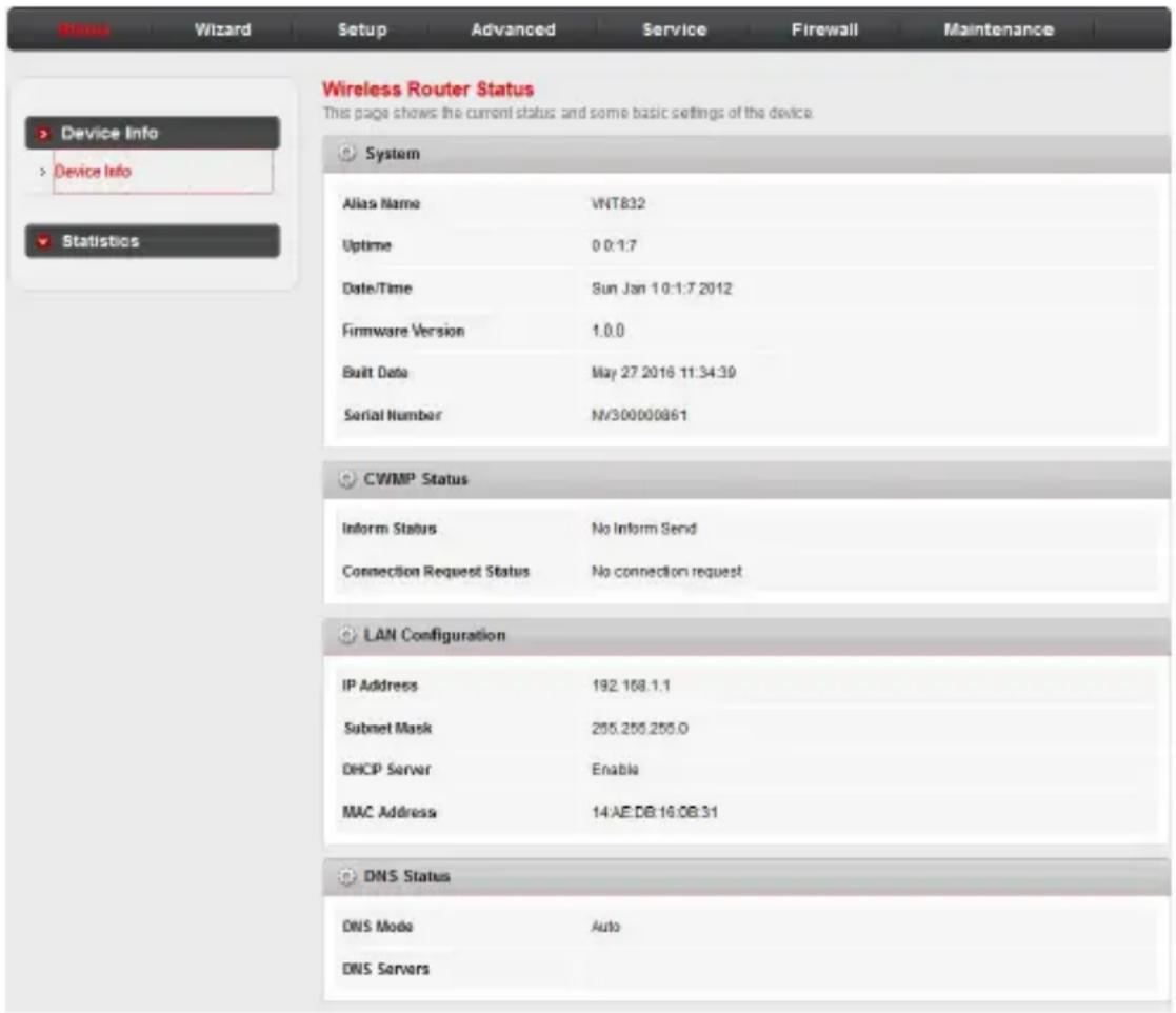
- STATUS: Allows you to view the information and statistics of the router.
- WIZARD: Allows you to start the fast configuration Wizard.
- SETUP: Allows you to configure the basic functions of the router.
- ADVANCED: Allows you to configure the advanced functions of the router.
- SERVICE: Allows you to configure extended network features.
- FIREWALL: Allows you to secure your router from unauthorized devices and/or services.
- MAINTENANCE: Allows you to manage firmware updates, passwords, network time, and diagnostics.
Configure your router
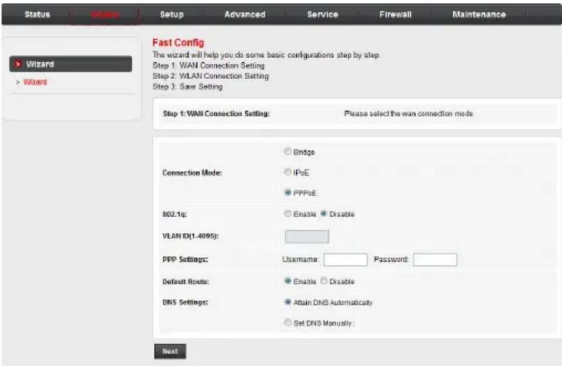
Fast configuration
The Wizard feature can guide you through the basic configuration of the router step by step. After running the Wizard you can close the web management page and then start connecting devices to the router.
- Click the Wizard menu to start the fast configuration.
- Select or input the information on the page as appropriate to configure the WAN settings. Click Next to proceed.
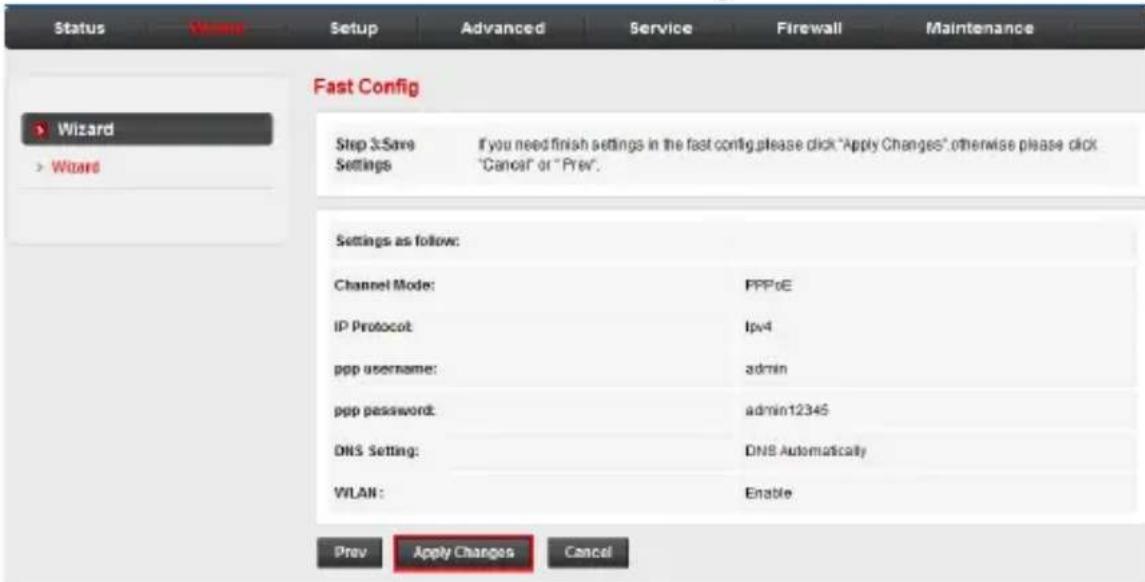
- Preview the settings and click Apply Changes to save the settings. Otherwise, click Prev to return to the previous page or click Cancel to cancel the fast configuration.
Configure your router
Status
The Status menu allows you to view the information and statistics of the router. Choose this menu and you can see the next sub-menus: Device info and Statistics.
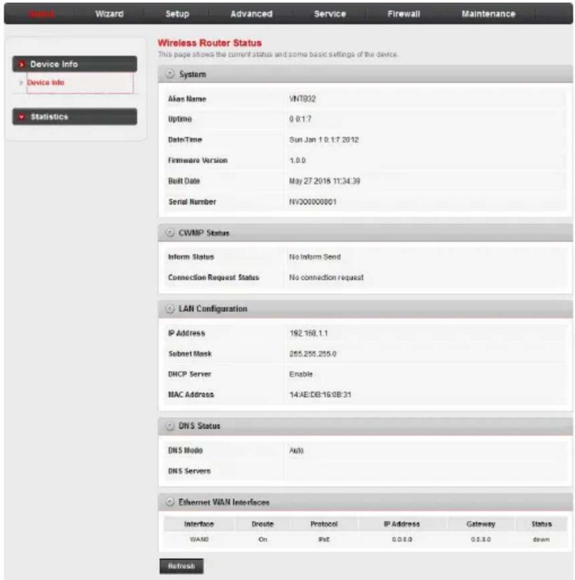
Device info: Wireless Router Status
Click the Status menu. The Wireless Router Status page under the Device info sub-menu in the left pane opens, displaying the basic information of the router, including system, LAN configuration, DNS status and Ethernet WAN interfaces.
Configure your router
Status
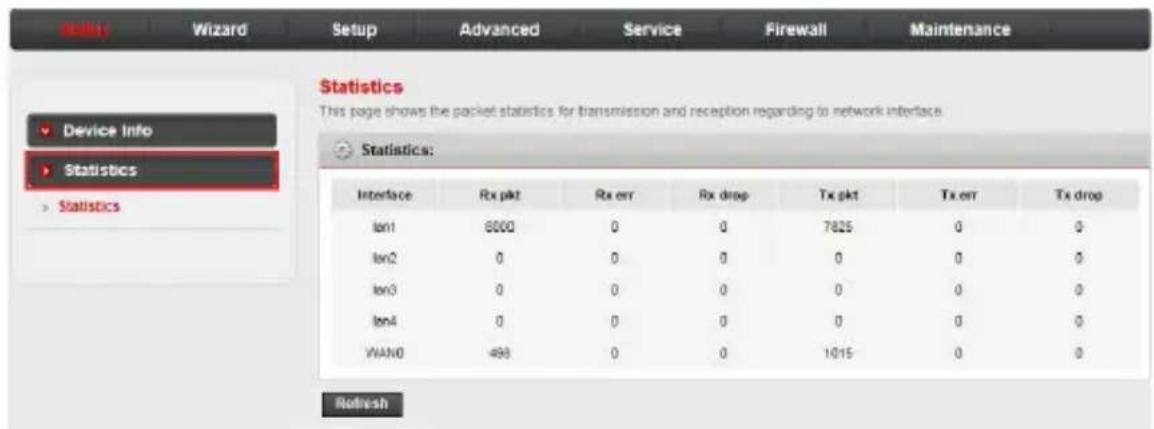
Statistics
Click the Statistics sub-menu. The page displays the packet statistics for transmission and reception regarding network interface.
Configure your router
Setup
The Setup menu allows you to configure the functions of the router. Choose this menu and you can see the next sub-menus: WAN and LAN.
WAN: WAN Configuration
Click the Setup menu. The WAN Configuration page under the WAN sub-menu in the left pane opens. You can configure the parameters for the WAN interface of your router, such as channel mode, PPP settings and WAN IP settings.
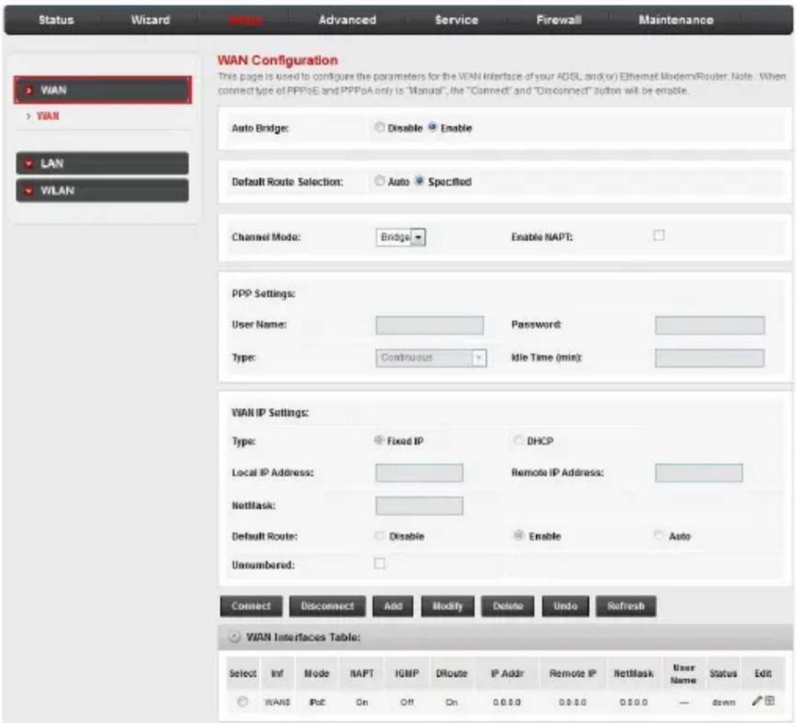
- Auto Bridge: Enable or disable the Auto Bridge Mode. If it is enabled, the child VNT832 router's DCHP mode will change to DCHP Relay automatically. See DCHP mode on page 21 for more details.
- Default Route Selection: Auto, Specified.
Configure your router
Setup
• Channel mode: It can be Bridge, IPoE or PPPoE.
- Enable NAPT: Enable or disable the NATP function.
- PPP User Name: User name of the PPP connection
- PPP Password: Password of the PPP connection.
• Type (PPP settings): Continuous, Manual or Connect On Demand.
- Idle Time (min): The idle time of the PPP connection when the type is Connect On Demand.
• Type (WAN IP settings): Fixed or DHCP.
- Local IP address: The IP address of the router.
- Remote IP address: The gateway's IP address of the router.
- NetMask: The subnet mask of the router.
- Default Route: The mode of the default route of the router.
- Unnumbered: Enable or disable IP unnumbered interface mode.
Configure your router
Setup
LAN: LAN Interface Setup
Click the LAN sub-menu in the left pane. The LAN Interface Setup page opens. You can configure the LAN interface of your router, such as changing the setting for IP address and subnet mask.
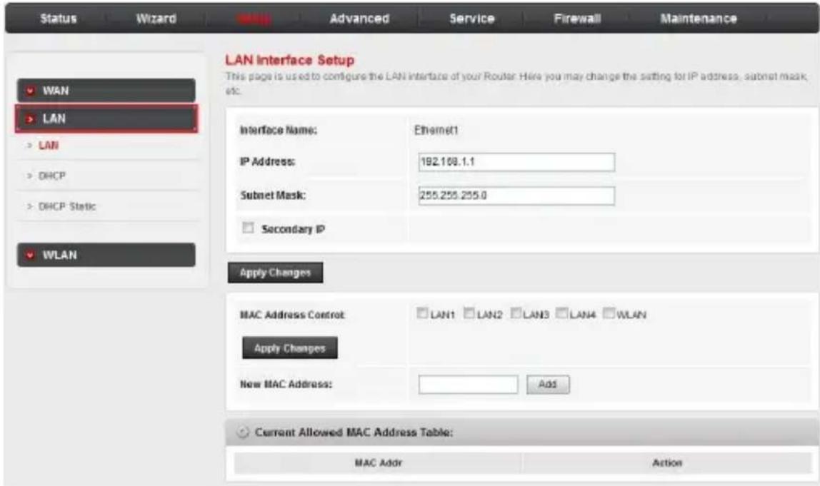
- IP Address: The IP address of the router's LAN interface. The default value is 192.168.1.1.
- Subnet Mask: The subnet mask of the router's LAN interface. The default value is 255.255.255.0.
- Secondary IP: If you enable the Secondary IP, you should configure another IP address and subnet mask for the LAN interface.
- MAC Address Control: Select the LAN interface on which you want to run MAC Address Control.
- New MAC Address: You can add a new MAC address.
- The Current Allowed MAC Address Table shows the current allowed MAC address list.
Configure your router
Setup
LAN: DHCP mode:
Click DHCP in the left pane. The DHCP Mode page opens. On this page, you can configure the DHCP mode of your router as None, DHCP Server or DHCP Relay.
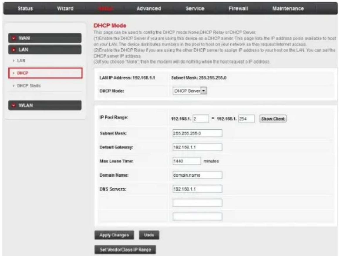
- DHCP Mode: Select one of the DHCP modes described below:
- None: The router will do nothing when the hosts require an IP address by DHCP protocol.
- DHCP Server: DHCP Server is used to configure correct TCP/IP protocol related parameters for the computer on you local network. If you enable the DHCP Server function, you can make the DHCP Server automatically configure the TCP/IP protocol parameters (such as IP address, subnet mask, gateway and DNS servers) for the computer on you local network.
- DHCP Relay: DHCP Relay is used if you are using the other DHCP Server to assign IP address to your Ethernet devices on the LAN. You can set the DHCP Server's IP address.
Configure your router
Setup

NOTES
- If you have more than four Ethernet devices and they are connected to the additional VNT832 router(s) you purchased, there is no need to change the DHCP mode setting of the child router(s). Once a child VNT832 router is connected with a parent VNT832 router, the child router enters Auto Bridge Mode, and all Ethernet devices obtain IP addresses from the parent router directly. See Plan and connect your system on page 4 for more details.
- If you have more than four Ethernet devices and you are using an existing non-VTech router as the parent router and VNT832 router(s) as the child router(s), you need to set the DHCP mode to DHCP Relay for the VNT832 router(s) manually and make sure the non-VTech router has the DHCP setting enabled, so that all Ethernet devices obtain IP addresses from the parent router directly.
- IP Pool Range: Enter the range of assignable IP addresses.
- Subnet Mask: The subnet mask of the router's LAN interface. The default value is 255.255.255.0.
- Default Gateway: Enter the IP address of the default gateway.
- Max Lease Time: Set the lease time for assigned IP addresses. When the lease time expires, the router may assign a new address for the client.
- Domain Name: Enter the domain name for the router.
- DNS Servers: Enter addresses for up to three DNS servers.
Configure your router
Setup
LAN: DHCP Static IP Configuration
In the left pane, click DHCP Static. The DHCP Static IP
Configuration page opens. On this page, you can set the DHCP address reservation rules. The DHCP Static IP table shows the reserved IP address and MAC address that have been set up for the DHCP Server.
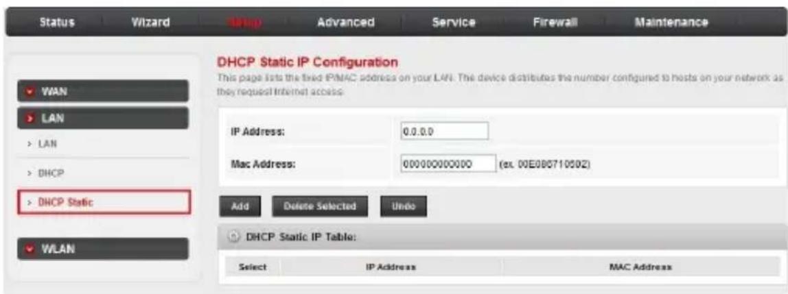
- IP Address: Manually input an IP address to add a static assignment.
• Mac Address: Manually input a MAC address to add a static assignment. - Click Add to add the static IP and associated MAC address to the Static IP table. The router searches the relevant entry in this table to assign an IP address according to the client's MAC address. If the router cannot find a corresponding static entry, it will choose an unallocated IP address from DHCP pool assigned to the client.
Configure your router
Setup
WLAN: Wireless Basic Settings
In the left pane, click WLAN. The Wireless Basic Settings page opens. On this page, you can configure the router if you plan to use the wireless LAN (Wi-Fi) features.
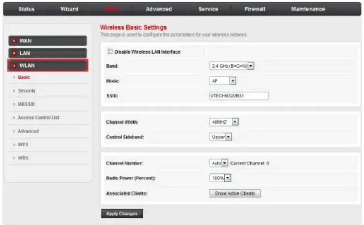
- Disable Wireless LAN Interface: Click to disable wireless functionality.
- Band: Select the wireless band standard: 2.4 GHz (B), 2.4 GHz (G), 2.4 GHz (B+G), 2.4 GHz (N), 2.4 GHz (G+N), 2.4 GHz (B+G+N)
- SSID: If necessary, edit the Server Set Identifier (SSID), that is, the Wi-Fi network name
- Channel Width: Select your preferred bandwidth: 20MHz, 40MHz, 20/40MHz. The lower bandwidth works best in busy Wi-Fi environments, and offers increased range.
- Control Sideband: When channel width is set to 40MHz, select the band to be used as the secondary channel: Upper, Lower. For channel numbers up to 7, select Lower; for channels up to 11, select Upper.
Configure your router
Setup
- Channel Number: Select the channel the router uses for Wi-Fi: Auto, 5,6,7,8,9,10,11. Unless you have specific requirements to use a specific channel, leave this setting at Auto.
- Radio Power (Percent): Select the power level of the Wi-Fi radio transmitter: 100, 80, 50, 25, 10 percent. Unless you have issues with signal strength and range, you should leave this setting at default.
- Associated Clients: Click the Show Active Clients button to display the Active Wireless Client Table. This table lists the MAC address, transmission, reception packet counters and encrypted status for each associated wireless client.
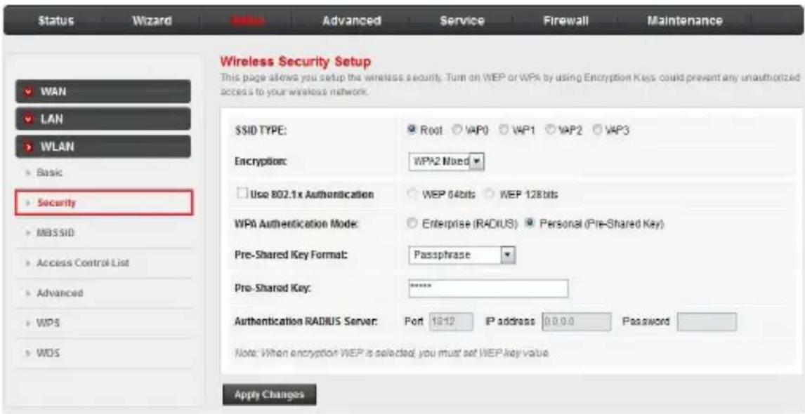
WLAN: Wireless Security Setup
In the left pane, click Security. The Wireless Security Setup page opens. This page allows you to prevent any unauthorized access to your wireless network.
Configure your router
Setup
- SSID Type: Root, VAP0, VAP1, VAP2, VAP3. Selecting Virtual Access Points VAP0 to VAP3 disables the security settings on this page. You must configure Virtual Access Points and VAP security on the MBSSID page.
- Encryption: Select the encryption type: WPA2 Mixed, WPA2(TKIP) WPA2(AES), WPA(AES), WPA(TKIP), WEP, None. None is not recommended except for certain configuration or troubleshooting situations.
- If you select WEP you must configure key length, key format, default Tx key, and encryption keys 1 to 4 (use the same number of characters for each key).
- Use 802.1x Authentication Mode: Select the authentication mode: Enterprise (RADIUS) or Personal (Pre-Shared Key). Select Enterprise (RADIUS) if using an external RADIUS server to authenticate clients.
- Pre-Shared Key Format: Select the pre-shared key format: Passphrase or Hex (64 characters). Passphrase can contain a–z, A–Z, 0–9, and symbols. Hex can contain 0–9, and upper case letters A–F.
- Pre-Shared Key: Enter the key for WPA or WEP authentication, from 8 to 63 characters.
- Authentication RADIUS Server: Enter the RADIUS server settings if using the RADIUS server for wireless client authentication. Port, IP address, Password
Configure your router
Setup
WLAN: Wireless Multiple BSSID Setup
In the left pane, click MBSSID. The Wireless Multiple BSSID Setup page opens. This page allows you to set four virtual access points (VAP0 to VAP3).
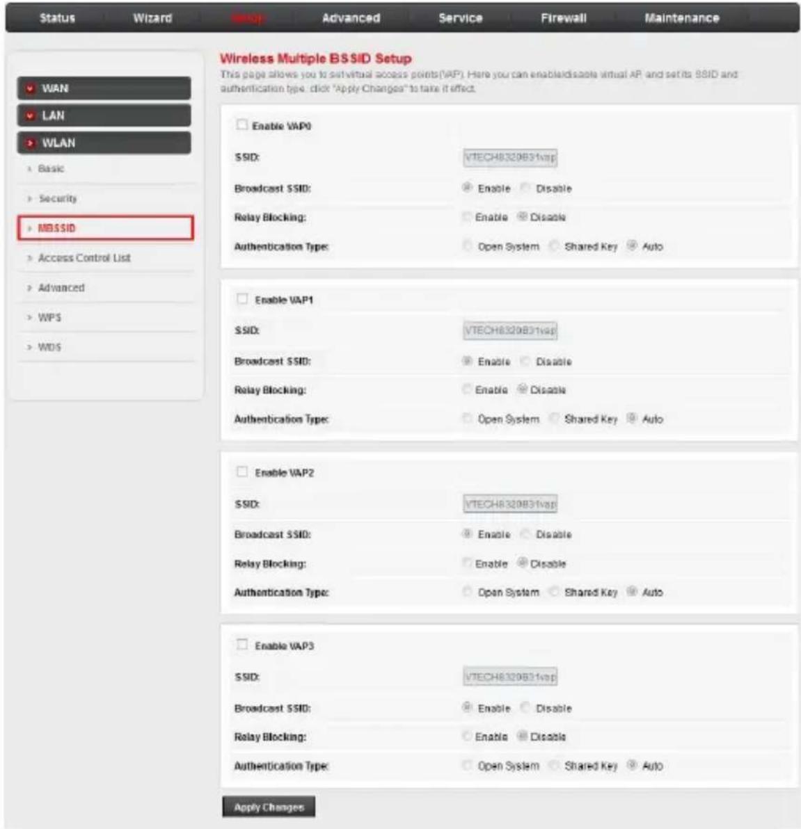
- Enable VAPn: Enable the virtual access point (VAP).
- SSID: Edit the SSID for the enabled VAP.
- Broadcast SSID: Set whether the router broadcasts the SSID: Enable, Disable. When enabled, wireless clients can display the SSID in their list of available networks.
Configure your router
Setup
- Relay Blocking: Set whether wireless clients using the same VAP are visible (and potentially have access) to each other: Enable, Disable
- Authentication Type: Select the authentication type: Open System, Shared Key, Auto
WLAN: Wireless Access Control
In the left pane, click Access Control List. The Wireless Access Control page opens. On this page, you can specify which clients can connect to your access point, based on device MAC addresses.
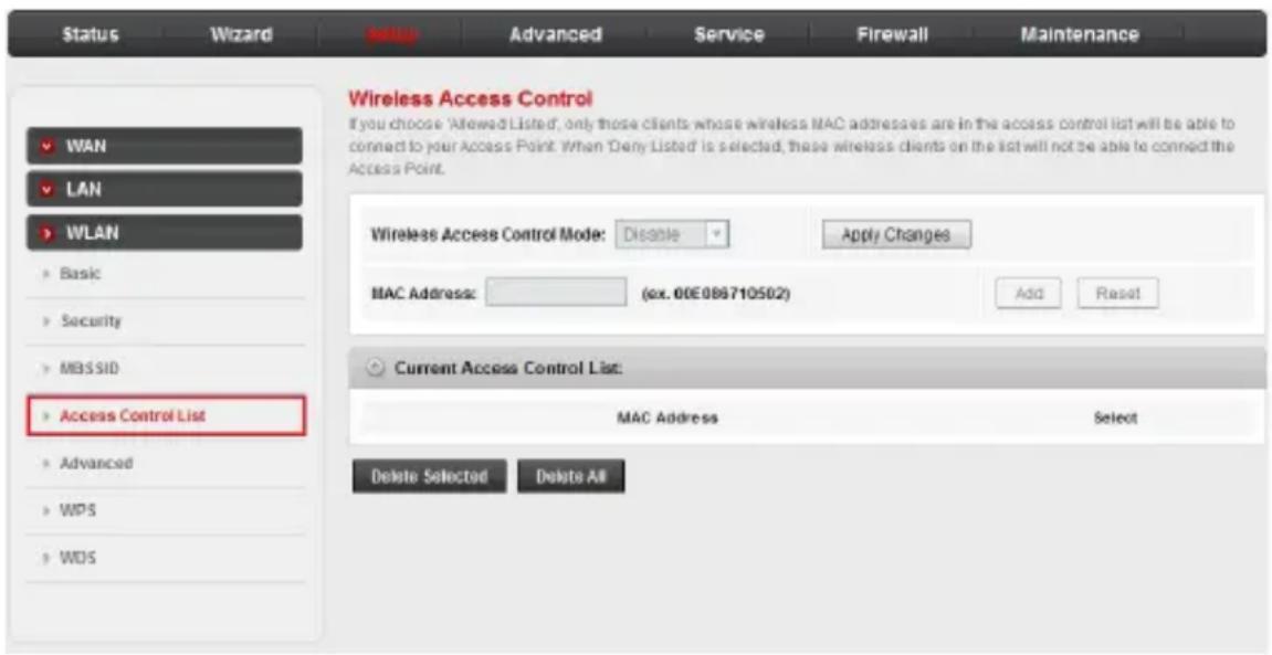
- Wireless Access Control Mode: Select the mode for device access control: Disable, Allow Listed, Deny Listed.
- MAC Address: If Allow Listed or Deny Listed are selected, enter a MAC address for each client you want to allow or deny access to the network. Click Add after entering each MAC address.
Click Apply Changes to apply the new control mode.
Configure your router
Setup
WLAN: Wireless Advanced Settings
In the left pane, click Advanced. The Wireless Advanced Settings page opens. Unless you are a technically advanced user with special requirements for your wireless network, you should not have to change these settings.
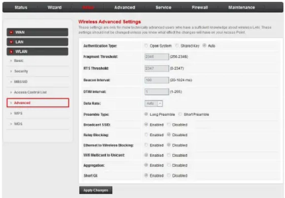
- Authentication Type: Open System, Shared Key, Auto
- Fragment Threshold: Sets the maximum packet size (maximum transmission unit, or MTU) before data is fragmented into multiple packets to accommodate devices in the transmission path that have lower MTU settings: 256–2346. Adjusting the threshold may correct a high packet error rate, although low settings can reduce performance over a wireless network.
- RTS Threshold: Sets the size of Mac protocol data unit (MPDU) below which a Request to Send/Clear to Send handshake between ADSL modem and router will not be performed: 0–2347 (bytes).
- Beacon Interval: Set the frequency of a beacon broadcast by the access point to synchronize the wireless network: 20–1024 ms
Configure your router
Setup
- DTIM Interval: Set the frequency of the Delivery Traffic Indication Message (DTIM): 1–255. When the access point has buffered broadcast or multicast messages for associated clients, it sends the next DTIM with a DTIM Interval value. Access point clients will awaken to receive the broadcast and multicast messages.
- Data Rate: Set the data transmission rate: Auto, 1–54M, MCS0–15. Leaving this setting at Auto will ensure the fastest available data rate, with automatic fallback to the best possible rate when the access point and client maximum speeds differ.
- Preamble Rate: Set the type of the Cyclic Redundancy Check (used for synchronizing router and clients, and detecting data transmission errors): Long Preamble, Short Preamble. In general, Long Preamble is compatible with older and newer devices. Long Preamble can be effective when there is network interference or signal strength is low. Short Preamble can improve performance if clients support the Short Preamble type.
- Broadcast SSID: Enabled, Disabled
- Relay Blocking: Enabled, Disabled
- Ethernet to Wireless Blocking: Enabled, Disabled.
- Wifi Multicast to Unicast: Enable this setting to have the router switch from multicast media (one media stream to multiple clients) streaming to unicast (multiple one-to-one sessions to multiple clients) streaming: Enabled, Disabled
- Aggregation: Enables or disables Aggregated MAC Protocol Data Unit (AMPDU), which can improve network performance in busy Wi-Fi environments : Enabled, Disabled. Overall, though, it can hamper performance when Wi-Fi signal is strong and few clients are connected.
- Short GI: Enables or disables short Guard Interval (GI): Enabled, Disabled. Short GI can increase the data rate by about 10% in certain environments, and when using 802.11n and 80211ac only.
Configure your router
Setup
WLAN: Wi-Fi Protected Setup
In the left pane, click WPS. The Wi-Fi Protected Setup page opens. WPS is a convenient method for wireless clients to connect to the network.
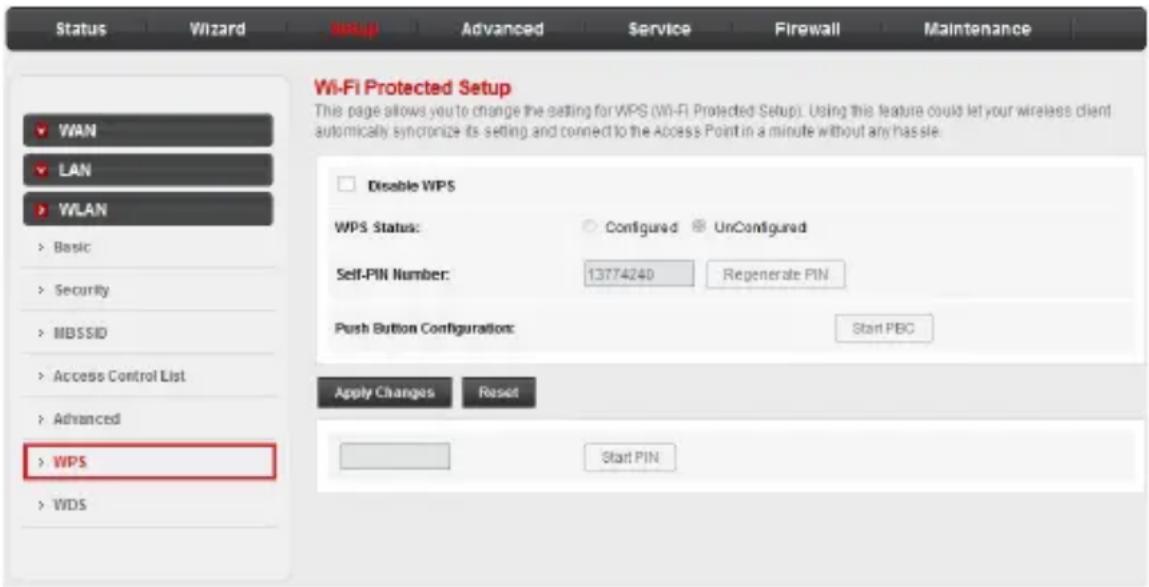
- Disable WPS: Click to disable Wi-Fi Protected Setup. Other methods of authentication will apply, such as entering a WPA2 passphrase.
- WPS Status: Configured, Unconfigured.
- Self-PIN Number: Set the 8-digit PIN that must be entered for clients to connect. The default PIN is provided on the label on the bottom of the router.
- Push Button Configuration: Click the PBC button to start Wi-Fi Protected Setup. You have two minutes to find the available wireless network on your device and connect to the router (you may also need to enter the PIN).
- Start PIN: Enter the client device's WPS PIN. After saving the client-generated WPS PIN, the client device can discover this router (some devices will display “WPS available” with the network name) in its list of detected networks. You can then easily connect to the router on your client device.
Configure your router
Setup
WLAN: WDS Settings
In the left pane, click WDS. The WDS Settings page opens. Wireless Distribution System (WDS) uses wireless media to communicate with other access points. In this way, you can expand the reach of your wireless network. On this page, you can enable WDS and add MAC addresses of the other devices/access points the router will communicate with.
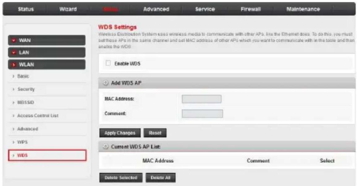
- Enable WDS: Click to enable WDS.
- MAC Address: Enter the MAC address of another device that will be another access point connected to the router.
- Comment: Enter any notes about the access point device name or location.
Click Apply Changes to add the new access point to the WDS AP list.
Configure your router
Advanced
The Advanced menu allows you to configure the advanced functions of the router. Choose this menu and you can see the next sub-menus: Route, NAT, QoS, Port Mapping, Others.
Route: Routing configuration
Click the Route sub-menu in the left pane. The Routing Configuration page opens. On this page, you can enable static routes, configure routing information, and add and delete IP routes.
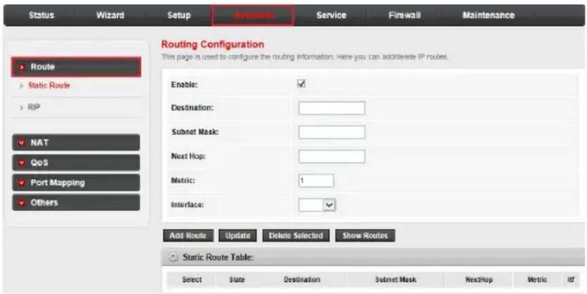
- Destination: Specifies the IP network address of the final destination.
- Subnet Mask: Enter the subnet mask for this destination.
- Next Hop: Enter the IP address of the gateway. The gateway is an immediate neighbour of your Router that will forward the packet to the destination. On the LAN, the gateway must be a router on the same segment as your Router; over Internet (WAN), the gateway must be the IP address of one of the remote nodes.
- Metric: Metric represents the cost of transmission for routing purposes. IP Routing uses hop count as the measurement of cost, with a minimum of 1 for directly connected networks. Enter a number that approximates the cost for this link. The number needs not to be precise, but it must between 1 and 15. In practice, 2 or 3 is usually a good number.
- Interface: The WAN interface to which a static route is to be applied.
- The Static Route Table shows the current static route entries.
Configure your router
Advanced
Route: RIP Configuration
Click RIP in the left pane. The RIP Configuration page opens.
Routing Information Protocol (RIP) is an internet protocol you can setup to share routing table information with other routing devices.
On this page, you can configure the RIP settings such as enabling or disabling the RIP function.
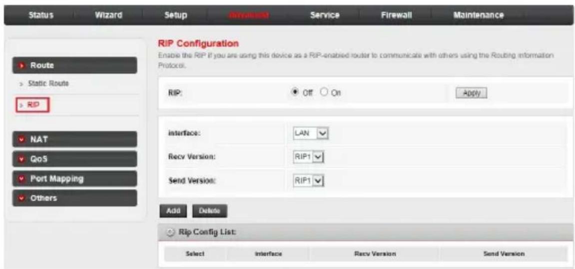
- RIP: Enable or disable the RIP function of the router.
- Interface: The interface on which you want to enable RIP.
- Recv Version: Indicates the RIP version in which information must be passed to the device it can be accepted into its routing table.
- Send Version: Indicates the RIP version this interface will use when it sends its route information to the other device.
- The RIP Config List shows the current RIP setting of the device.
Configure your router
Advanced
NAT: DMZ
You can set up the Network Address Translation (NAT) function in the NAT sub-menu.
Click the NAT sub-menu in the left pane. The DMZ page opens. On this page, you can configure the DMZ settings.
A Demilitarized Zone (DMZ) is a host between a private local network and the outside public network. Users of the public network outside the company can access the DMZ host. It allows you to expose one network user to the internet for some special-purpose services such as internet gaming or video conferencing. DMZ hosting forwards all the ports at the same time to one computer. You should assign a static IP address to the destination computer before you use this feature.
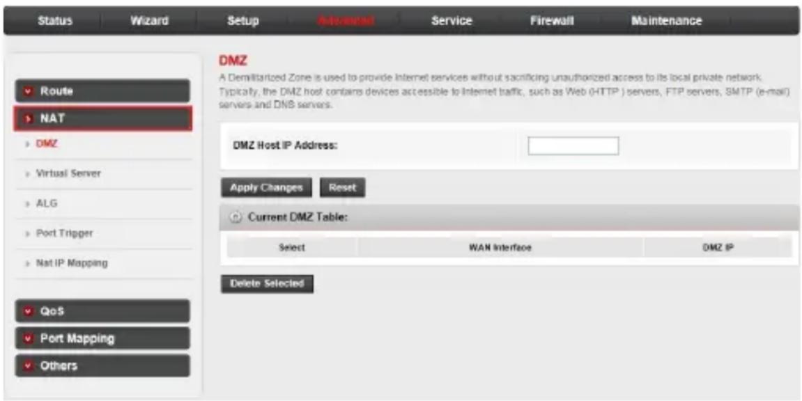
- DMZ Host IP Address: Enter the specified IP Address for DMZ host on the LAN side.
Configure your router
Advanced
NAT: Virtual server
Click Virtual Server in the left pane. The Virtual Server page opens. This page allows you to configure the virtual server so that others can access the server through the Gateway.
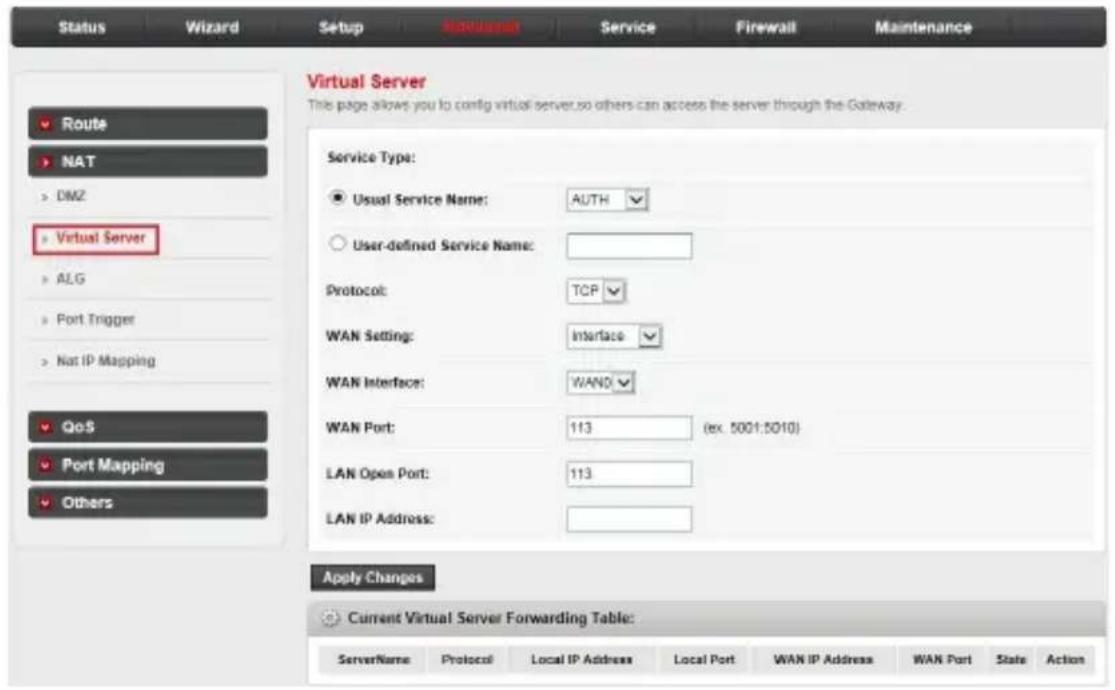
- Usual Service Name & User-defined Service Name: The name of this virtual server.
- Protocol: The protocol of this virtual server used: TCP or UDP.
- WAN Setting: The WAN setting of this virtual server used: Interface or IP address.
- WAN Interface: The interface on which the virtual server used on WAN side.
- WAN Port: The open port on WAN side. It can be either a single port or a port range.
• LAN Open Port: Enter the specific start and end port number you want to forward. If it is one port only, enter the same end port and start port number. For example, if you want to set the FTP virtual server, set the start and end port number to 21.
• LAN IP Address: The IP address of the host which provides the service on LAN side. - The Current Virtual Server Forwarding Table displays the information about the virtual servers you established.
Configure your router
Advanced
NAT: ALG
Click ALG in the left pane. The NAT ALG and Pass-Through page opens. On this page, you can configure the Application Layer Gateway (ALG) setting.
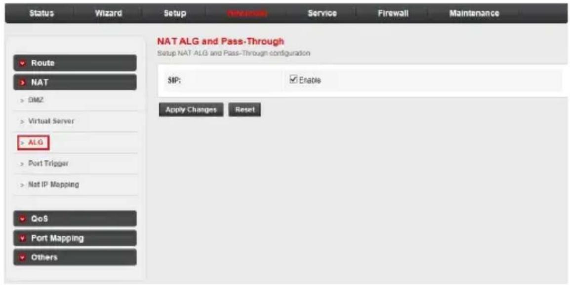
- SIP: Enable.
Configure your router
Advanced
NAT: NAT port trigger
Click Port Trigger in the left pane. Port trigger is used to restrict certain types of data packets from your local network to the internet. Use of such filters can be helpful in securing and restricting your local network. On this page, you can configure the port trigger rules.
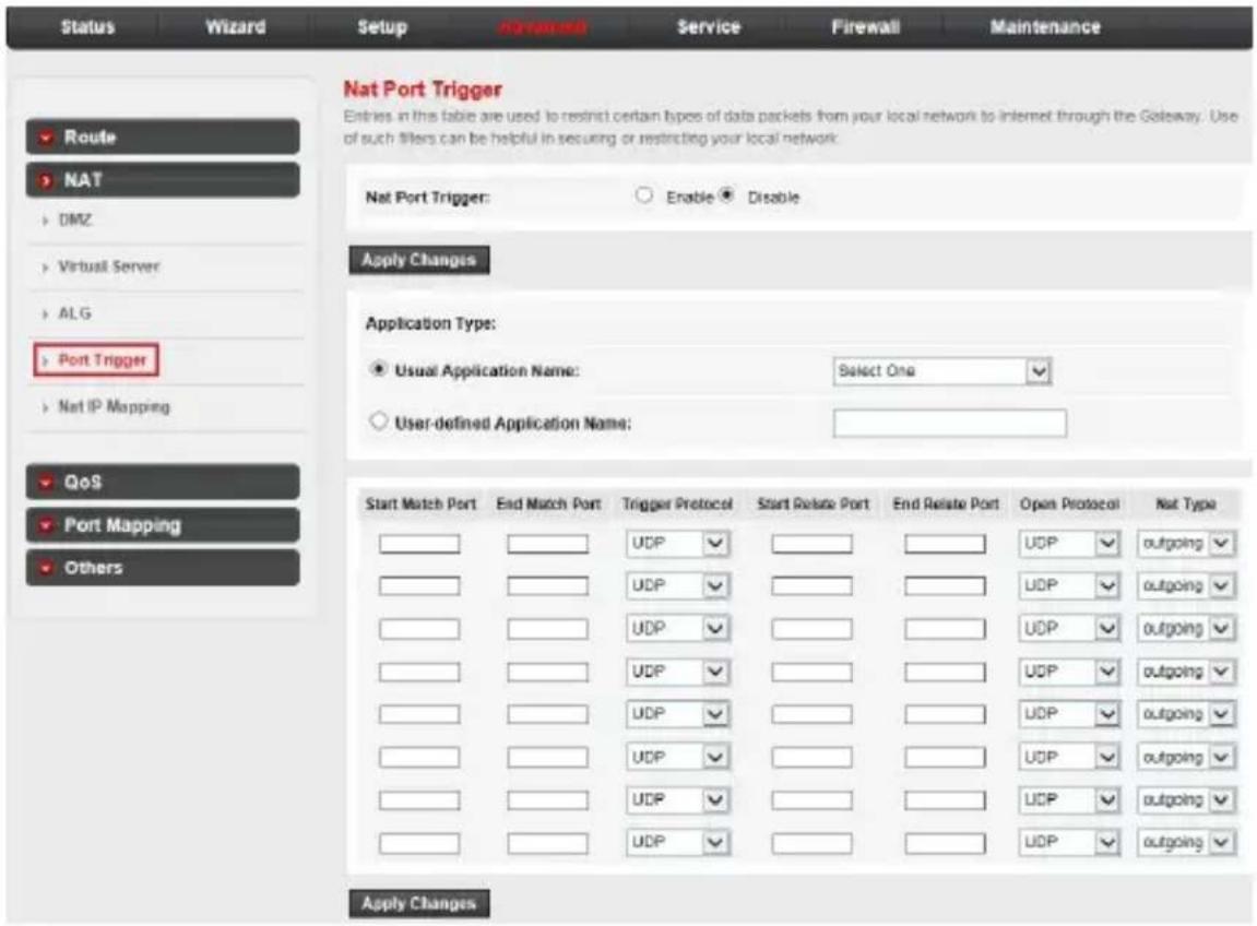
- Nat Port Trigger: Enable or disable the port trigger function on the device.
• Application Type: Select the service from the Usual Application Name or define the name from User-defined Application Name. - Start Match Port / End Match port: The start and end port to match.
- Trigger Protocol: The protocol to trigger the rule. It can be TCP, UDP or TCP/UDP.
- Start Relate Port / End Relate Port: The start and end relate port.
- Open Protocol: It can be TCP, UDP or TCP/UDP.
• NAT Type: It can be outgoing or incoming.
Configure your router
Advanced
NAT: NAT IP mapping
Click Nat IP Mapping in the left pane. NAT IP mapping allows you to configure one IP pool for specified source IP address from LAN, so a packet whose source IP is in range of the specified address will select one IP address from the pool for NAT.
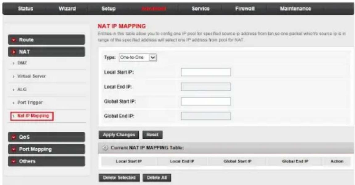
- Type: The type of this mapping rule. It can be One-to-One, Many-to-One, Many-to-Many or One-to-Many.
• One-to-One: One local IP will be mapped to one global IP.
- Many-to-One: The IP between Local Start IP and Local End IP will be mapped to a global IP.
- Many-to-Many: The IP between Local Start IP and Local End IP will be mapped to the IP between Global Start IP and Global End IP.
- One-to-Many: One local IP will be mapped to any of the IP between Global Start IP and Global End IP.
- Local Start IP: A local IP address.
- Local End IP: A local IP address.
- Global Start IP: A global IP address used for NAT.
- Global End IP: A global IP address used for NAT.
Configure your router
Advanced
QoS: IP QoS
The router provides a control mechanism that serves traffic with different priorities. The traffic is classified by criteria. A classification rule contains three configuration blocks: Quality of Service (QoS) policy, schedule mode and traffic rule. The QoS policy enables you to classify packet on the basis of various fields in the packet. The schedule mode enables you to configure which priority queue you want to use. The traffic rule enables you to assign the precedence or add marker for different streams.
To configure IP QoS, click the QoS sub-menu in the left pane. The IP QoS page opens. On this page, you can enable or disable the IP QoS and configure the rules if necessary.
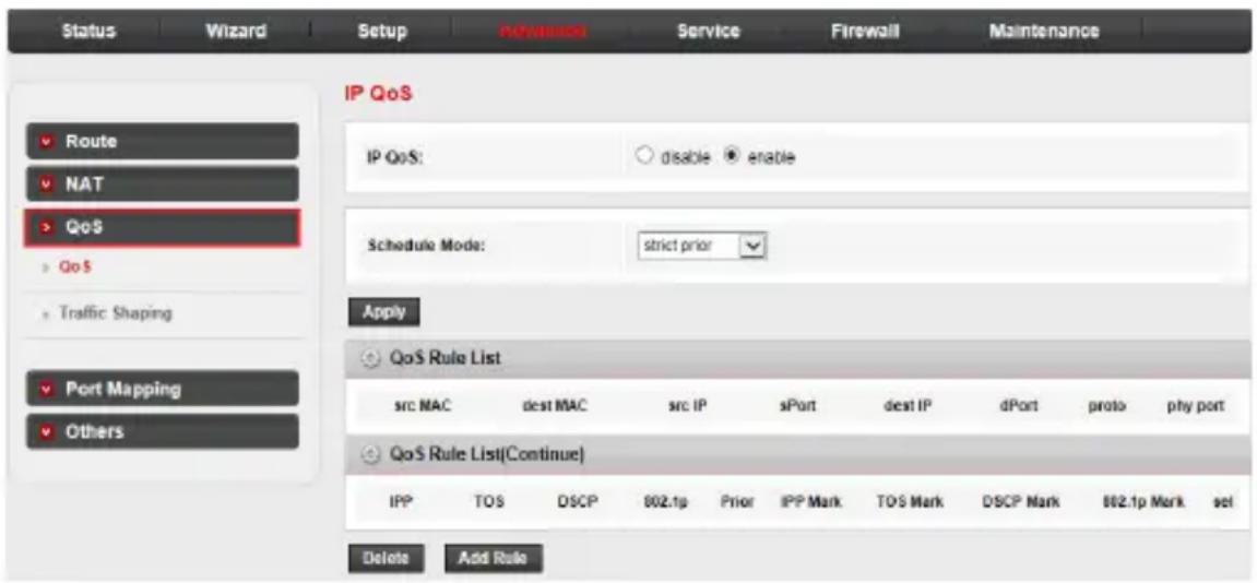
- IP QoS: Enable or disable the IP QoS function on the device.
-
Schedule Mode: The schedule mode of the IP QoS function. It can be strict prior or WFQ (4:3:2:1).
-
Strict Prior: Traffic with different priority will be sent by its priority. The higher priority the traffic is, the higher priority the traffic will be sent out.
- WFQ (4:3:2:1): Traffic with different priority will be sent in proportion of its priority. The four priority traffic will be sent out in proportion to 4:3:2:1.
Configure your router
Advanced
QoS: IP QoS traffic shaping:
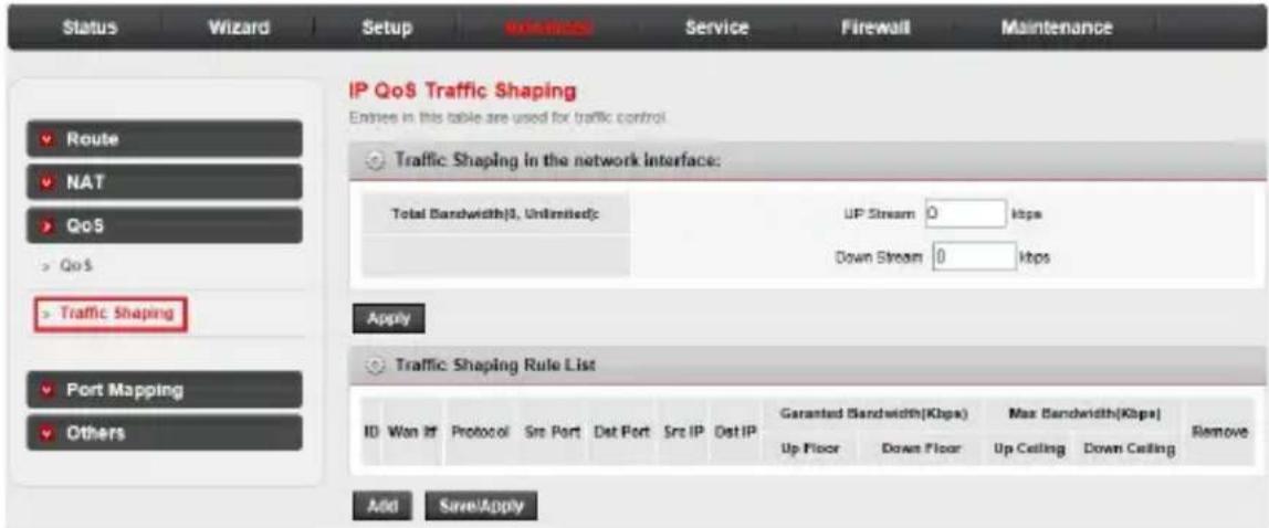
Click Traffic Shaping in the left pane. The IP QoS Traffic Shaping page opens. The tables on this page are used for traffic control. You can add traffic shaping rules in the list.
Configure your router
Advanced
Port Mapping Configuration
The router provides multiple interface groups and supports up to five interface groups including one default group. Traffic coming from one interface of a group can only be flowed to the interfaces in the same interface group. Thus, the device can isolate traffic from group to group for some applications. By default, all the interfaces (LAN and WAN) belong to the default group, and the other four groups are all empty. It is possible to assign any interface to any group but only one group.
Click the Port Mapping sub-menu in the left pane. The Port Mapping Configuration page opens.
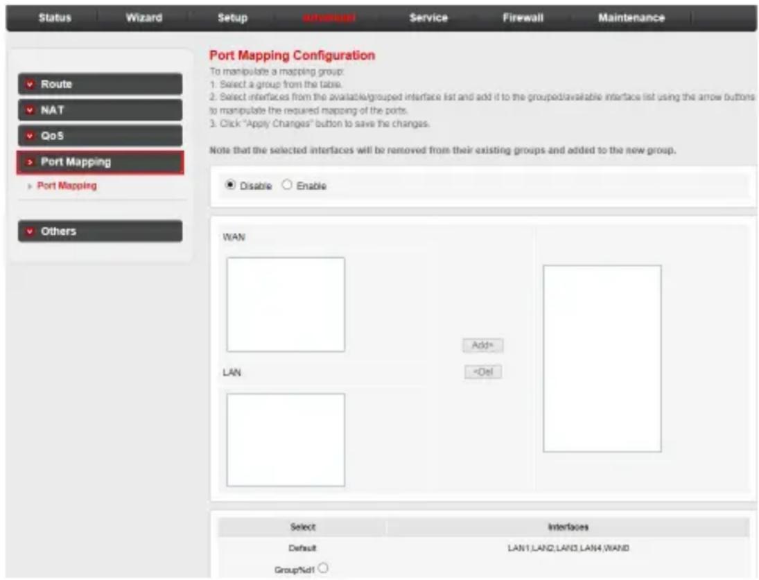
To manipulate a mapping group:
- Select a group from the table, then you can see the available interface (LAN and WAN) and grouped interface list.
- Select interfaces from the available and grouped interface list and add them to the interface group using the Add> button or delete them using the <Del button.
- Click Apply Changes to finish the configuration.
Configure your router
Advanced
Others: Bridge Setting
Click the Others sub-menu in the left pane. The Bridge Setting page opens. Here you can configure the bridge parameters and view the information on the bridge and its attached ports.
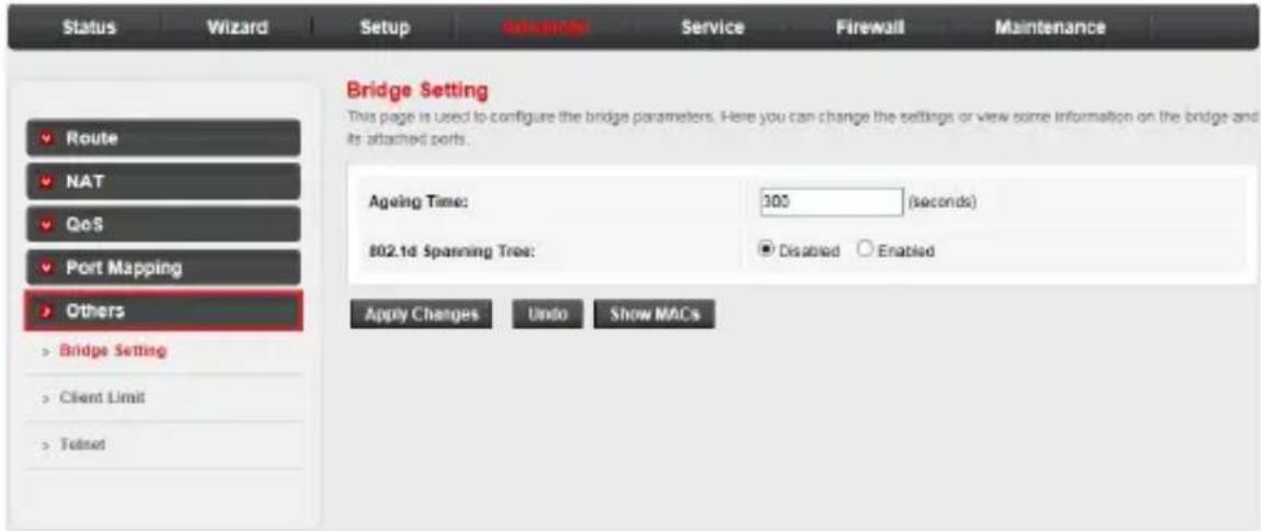
Click the Show MACs button and you will see the current Forwarding Table of the router.
- Ageing Time: The time for the MAC address to age out. If a frame does not come from a certain MAC address within the Ageing Time, the bridge will delete that address from the Forwarding Table.
- 802.1d Spanning Tree: Enable or disable the spanning tree protocol.
Configure your router
Advanced
Others: Client limit configuration
Click Client Limit in the left pane. The Client Limit Configuration page opens. On this page, you can enable or disable the client limit function and set the maximum number of device that can access the internet.
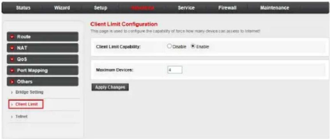
- Client Limit Capability: Enable or disable the client limit function.
• Maximum Devices: The maximum number of devices can access to the Internet.
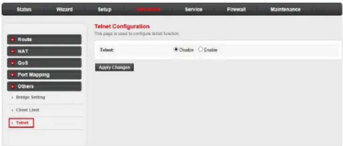
Others: Telnet
Click Telnet in the left pane. The Telnet Configuration page opens. On this page, you can enable or disable the Telnet function.
Configure your router
Service
Choose the Service menu and you can see the next sub-menus: UPnP, DNS, DDNS and USB Storage.
UPnP
Universal Plug and Play networking protocol (UPnP) is a feature that requires the operating system to support the UPnP application. LAN hosts can request a specific port translation on router by UPnP, so the external hosts can access the resources on the internal hosts when needed.
Click the UPnP sub-menu in the left pane. The UPnP Configuration page opens. On this page, you can configure the Universal Plug and Play networking protocol.
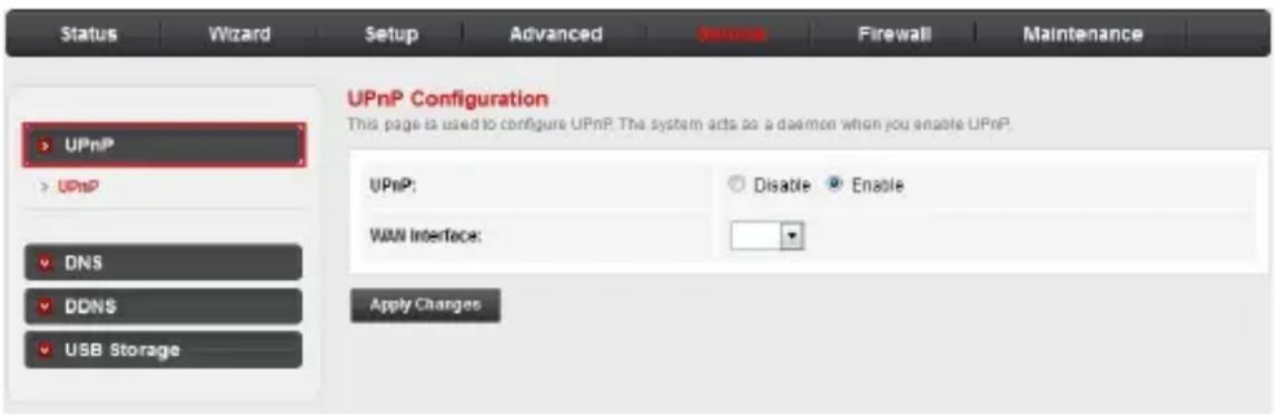
- UPnP: Enable or disable the UPnP function.
- WAN Interface: Choose which interface runs the UPnP function.
Configure your router
Service
DNS Configuration
Click the DNS sub-menu in the left pane. The DNS Configuration page opens. On this page, you can configure the IP address of the DNS server for DNS relay.
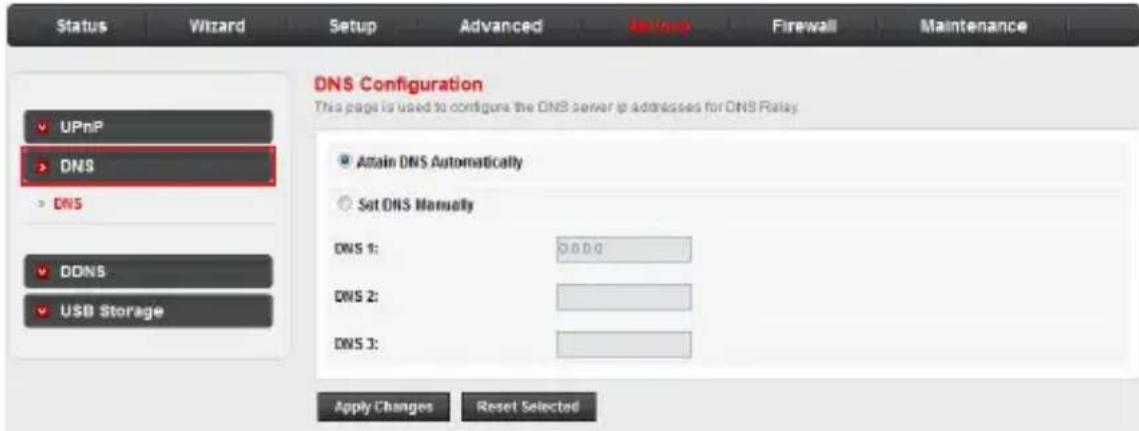
- Attain DNS Automatically: The device will use the DNS servers which are obtained by the WAN interface via the auto-configuration mechanism.
- Set DNS Manually: Configure the DNS IP address manually.
Configure your router
Service
Dynamic DNS Configuration
Dynamic Domain Name Server (DDNS) allows you to point a hostname to a dynamic or static IP address or URL.
Click the DDNS sub-menu in the left pane. The Dynamic DNS Configuration page opens. On this page, you can configure the DDNS settings.
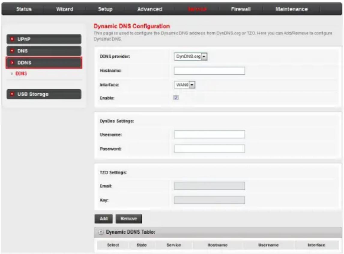
- DDNS provider: There are two DDNS providers to be selected in order to register your device: DynDNS.org and TZO.
- Hostname: Domain name to be registered with the DDNS server.
- Interface: The WAN interface over which your device will be accessed.
- Enable: Enable or disable the registration account for the DDNS server.
- Username: User name assigned by the DDNS provider.
- Password: Password assigned by the DDNS provider.
Configure your router
Service
USB Storage
Click the USB Storage sub-menu in the left pane. The USB
Storage page opens. On this page, you can enable or disable USB functionality.
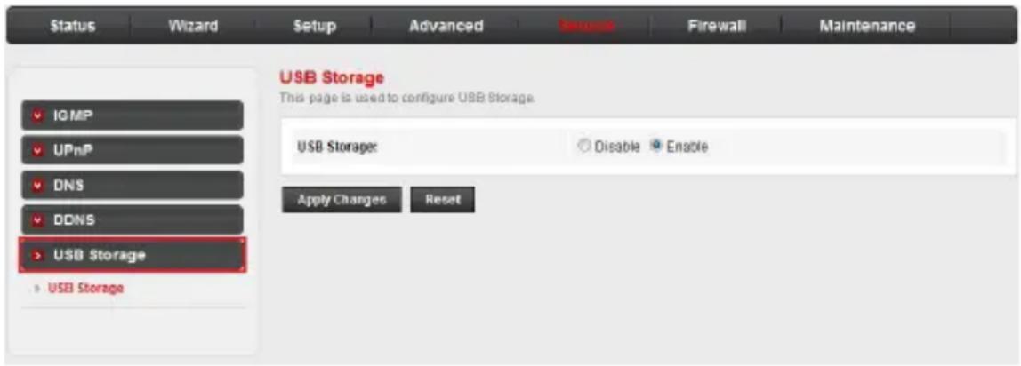
Once enabled, you can connect a USB drive to the router and share files (via FTP) between devices connected to the network.
To share files on a connected USB drive:
- In the address field of your web browser, enter ftp:// followed by the IP address of the router (usually 192.168.1.1).
- Log in to the router using your administrator account username and password.
The top-level folder of your USB drive should appear in your browser.
- From there, you can navigate to and access the desired files and folders on your USB drive.

NOTE
- In order to upload and download files, use your preferred FTP client.
Configure your router
Firewall
The Firewall menu includes the following sub-menus: MAC Filter, IP/Port Filter, URL Filter and DoS.
MAC filter
In order to manage your local network better, you can use the MAC address filter function to control internet access.
Click the MAC Filter sub-menu in the left pane. The MAC Filtering page opens. On this page, you can set the MAC filtering rules.
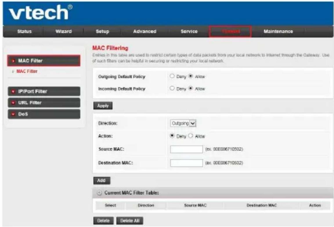
- Outgoing/Incoming Default Policy: The default action of outgoing/incoming connection. It can be Deny or Allow. If the connection does not match any MAC filtering rules, the router will handle the connection with the default action you have set.
• Direction: The direction of the filter entry (Outgoing or Incoming). - Action: The action of the filter entry. It can be Deny or Allow. If the action is Deny, the connection matching the filter rule will be denied; if the action is Allow, the connection matching the filter rule will be allowed.
Configure your router
Firewall
- Source MAC: The source MAC address of the filter entry. An empty field means it matches any source MAC address.
- Destination MAC: The destination MAC address of the filter entry. An empty field means it matches any destination MAC address.
- The Current MAC Filter Table shows the current MAC filtering rules. You can delete the entry on the list.
IP/Port filter
Click the IP/Port Filter sub-menu in the left pane. The IP/Port Filtering page opens. On this page, you can set the IP/Port filter rules to secure or restrict your local network. The default actions of the outgoing and incoming connection are shown on the top of the page.
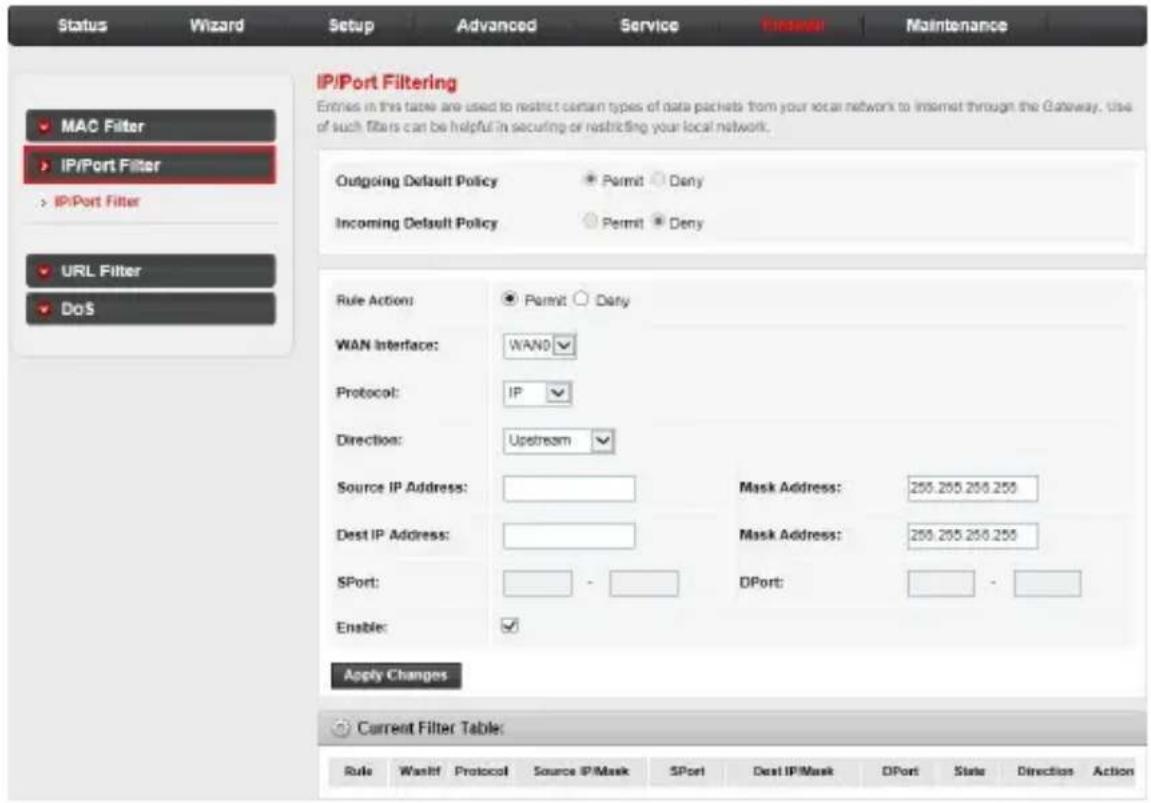
- Rule Action: The filter mode of this entry. It can be Permit or Deny. If the mode is Permit, the IP connection that matches the rule will be permitted; if the mode is Deny, the IP connection that matches the rule will be denied.
Configure your router
Firewall
IP/Port filtering (continued):
- Protocol: The protocol of this entry. It can be IP, ICMP, TCP or UDP.
- Direction: The direction of this entry. It can be Upstream or Downstream.
- Source IP Address/ Mask Address: The source IP address and mask address of the entry.
- Dest IP Address/ Mask Address: The destination IP address and mask address of the entry.
- SPort: If the protocol is TCP or UDP, you should set the source port of the entry. It can be a single port or a port range.
- DPort: If the protocol is TCP or UDP, you should set the destination port of the entry. It can be a single port or a port range.
- Enable: Enable or disable this filter entry.
- The Current Filter table shows the current filter rules. You can enable or disable or delete the filter entry.
Configure your router
Firewall
URL filter
In order to manage the site control of your local LAN client, you can use the URL filtering function to specify which site(s) cannot be accessed.
Click the URL Filter sub-menu in the left pane. The URL Blocking Configuration page opens. On this page, you can enable or disable the URL filtering function and add or delete the filtered keywords.
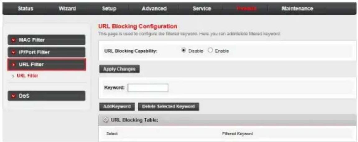
- URL Blocking Capability: Enable or disable the URL filtering function. If it is enabled, the access to the site which matches the keyword will be blocked by the router; if it is disabled, nothing will be done.
- Keyword: The keyword of the site you want to block.
- The URL Blocking Table shows the current URL filtering entry. You can delete the selected entry.
Configure your router
Firewall
DoS
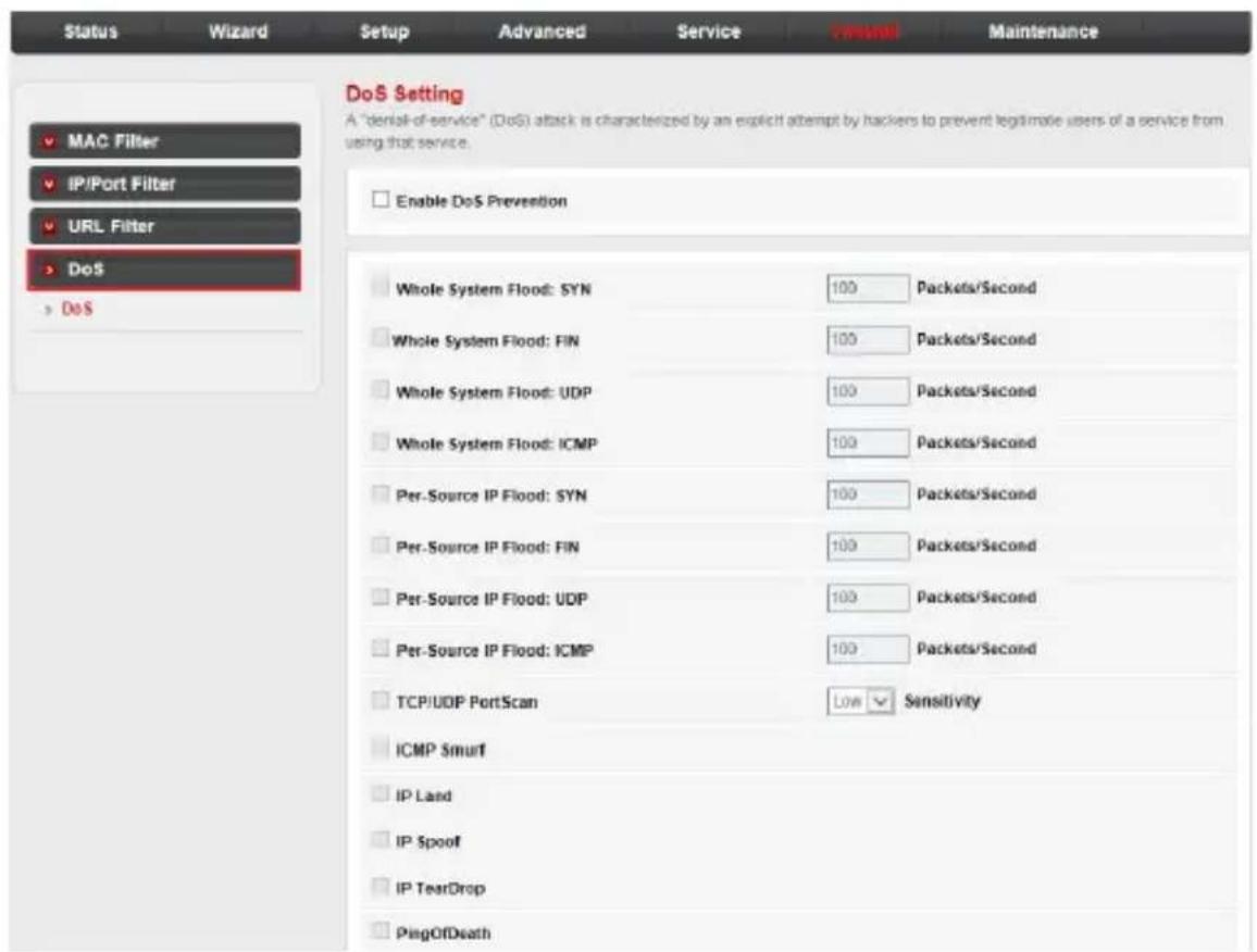
A Denial-of-Service (DoS) attack is characterized by an explicit attempt by hackers to prevent legitimate users of a service from using that service.
The router provides a protection of DoS attack.
Click the DoS sub-menu in the left pane. The DoS setting page opens. On this page, you can enable or disable the DoS prevention, configure the DoS parameters and specify the hack item.
Configure your router
Maintenance
Choose the Maintenance menu and you can see the next sub-menus: Update, Password, Reboot, Time, Log and Diagnostics.
Update: Upgrade firmware
The router supports firmware upgrade from HTTP.
Click the Update sub-menu in the left pane. The Upgrade Firmware page opens. On this page, you can upgrade the router firmware. Make sure the firmware or ROM file you want to use is on the local hard drive of your computer. Click Browse to find the local hard drive and locate the firmware or ROM file to be used for upgrade.
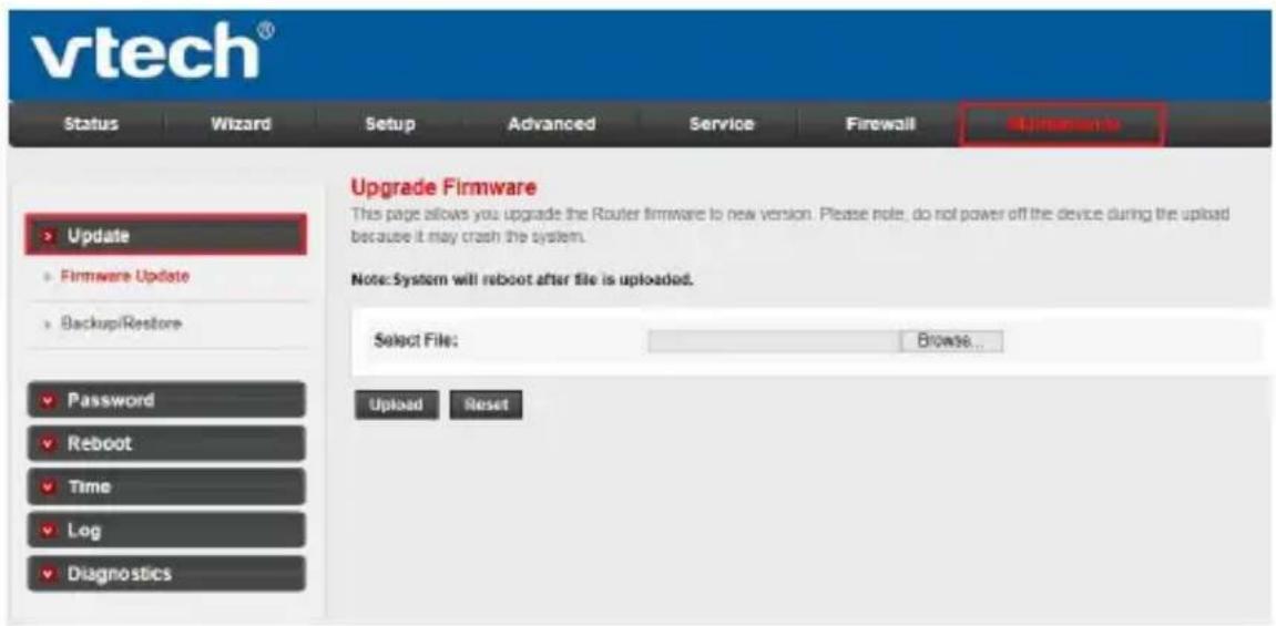
To upgrade the router's firmware:
- Download a more recent firmware upgrade file.
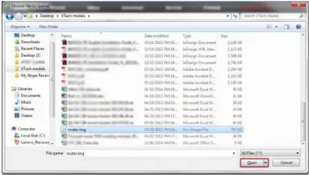
- Click the Browse... button.
- Choose the update file and click Open.
Configure your router Maintenance
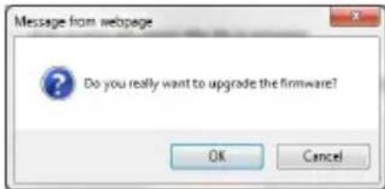
4. Click the Upload button.
5. When the confirmation message appears, click OK to proceed.
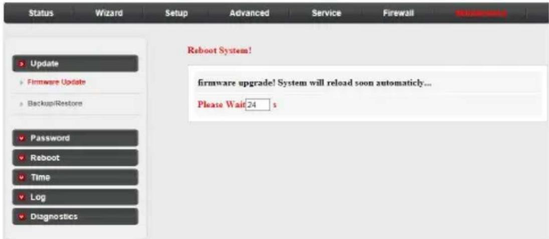
6. After the firmware file is uploaded, the system starts a 30-second countdown and then reboots. You need to login to the web management page again.

NOTES
• After the firmware is upgraded, we recommend resetting the router to default settings.
- For the router's back-end firmware upgrade, ensure the FTP server option is enabled under the Service menu. See FTP server on page 36 for details.
Configure your router
Maintenance
Update: Backup/restore settings:
Click Backup/Restore in the left pane. The Backup/Restore Settings page opens. On this page, you can save the current configuration settings to a file or restore the settings from a configuration file.
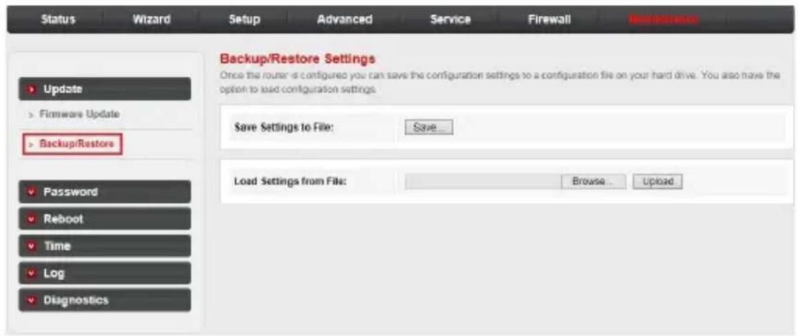
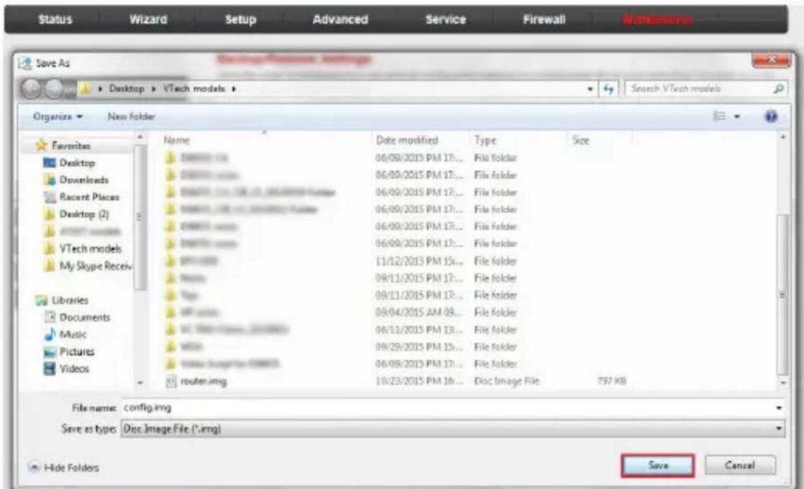
To back up the router's current settings:
- Click the Save... button.
- Click Save to save the file as the appointed file.
Configure your router Maintenance
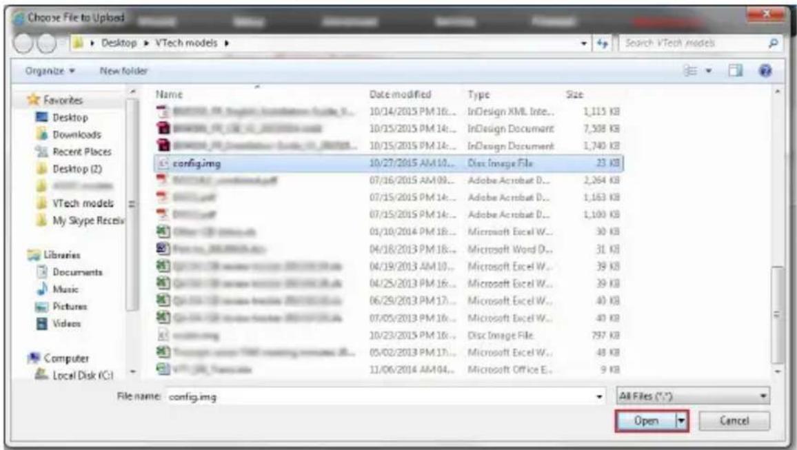
To restore the router's current settings:
- Click the Browse... button.
- Choose the file which you have saved and click Open.
- Click Upload.
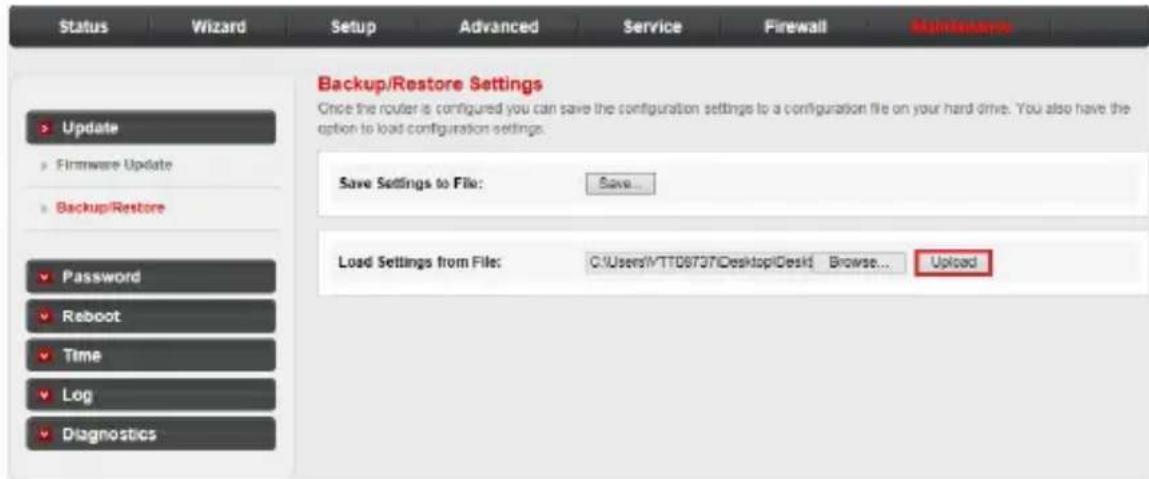
- A pop-up window will appear asking for confirmation of restoring the settings. Click OK to proceed.
- After the file is uploaded, the system starts a countdown and then reboots. You need to login to the web management page again.
Configure your router
Maintenance
Password: User account configuration
Click the Password sub-menu in the left pane. The User Account Configuration page opens. On this page, you can add a user account to access the web management page and modify the password of the specified user.
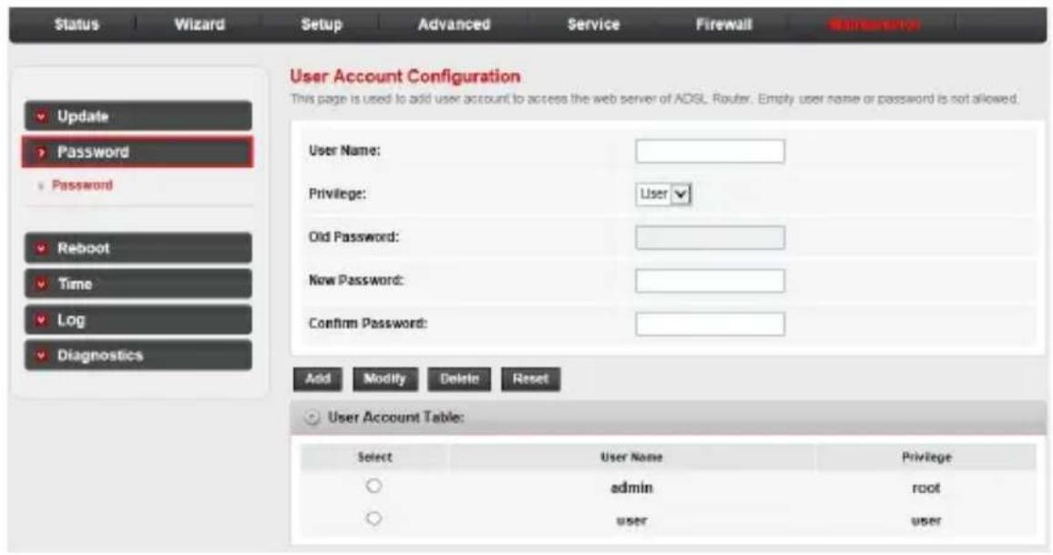
To create an account:
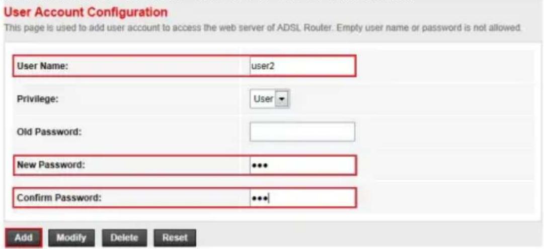
- Type a user name in the User Name input box, and then enter a password in the New Password and Confirm Password input boxes.
- Click Add to create the new user account.
Configure your router Maintenance
To change the password of an account:
- Select an account for which you want to change the password.
| User Account Table: | ||
| Select | User Name | Privilege |
| admin | root | |
| user | user | |
| user2 | user | |
- Fill in the Old Password, New Password and Confirm Password input boxes, and then click Modify to save it.

NOTE
- If you login to the web management page with an administrative account, you can change the password of all accounts. The default user name is admin and the password is 12345.
Configure your router
Maintenance
Reboot
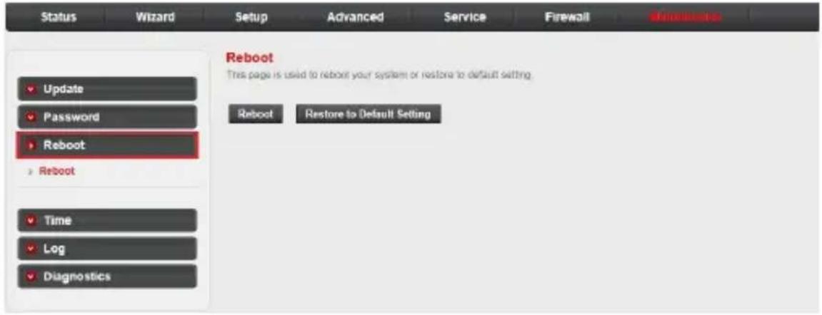
Click the Reboot sub-menu in the left pane. The Reboot page opens. On this page, you can reboot your system or restore the router to default settings.
Configure your router
Maintenance
Time
Simple Network Timing Protocol (SNTP) is a protocol used to synchronize the system time with the public SNTP server.
System time configuration:
Click the Time sub-menu in the left pane. The System Time Configuration page opens. On this page, you can configure the system time.
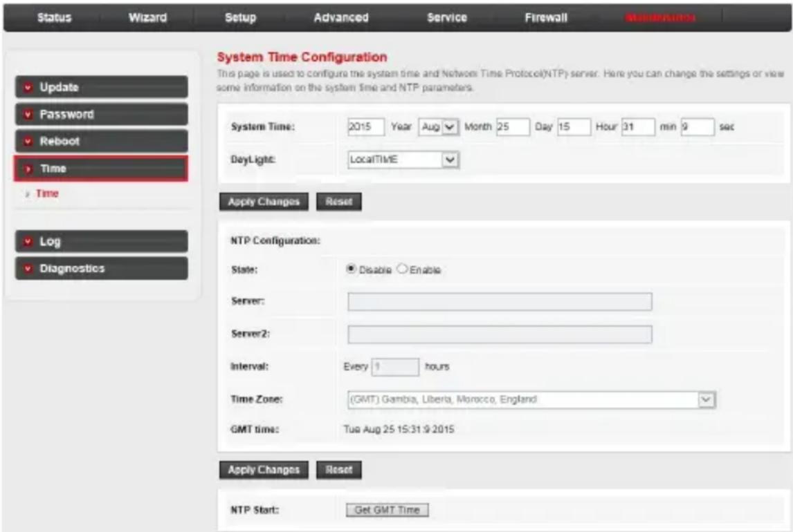
- Server/Server2: The IP address or the host name of the NTP server.
- Interval: The interval time of NTP function
- Time Zone: The time zone in which the device resides.
- When you set the NTP configuration correctly, press the button Get GMT Time to start the NTP function. Then, you can see the GMT time obtained from NTP server.
Configure your router
Maintenance
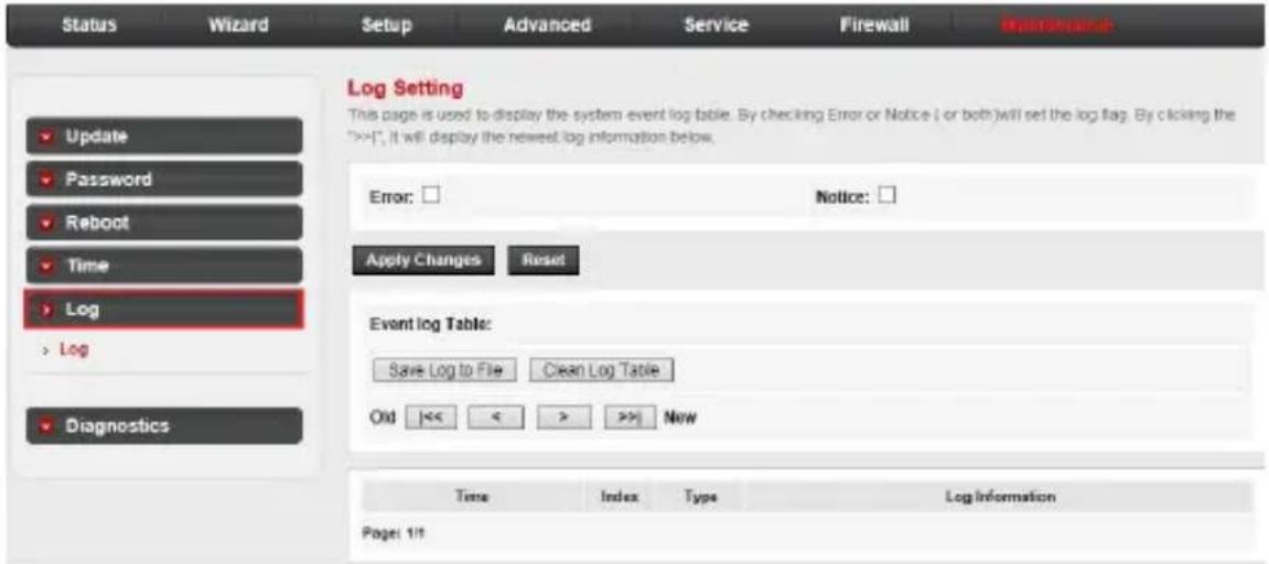
Log: Log setting
Click the Log sub-menu in the left pane. The Log Setting page opens. On this page, you can configure the parameters of the system log and view the system log information.
Diagnostics: Ping
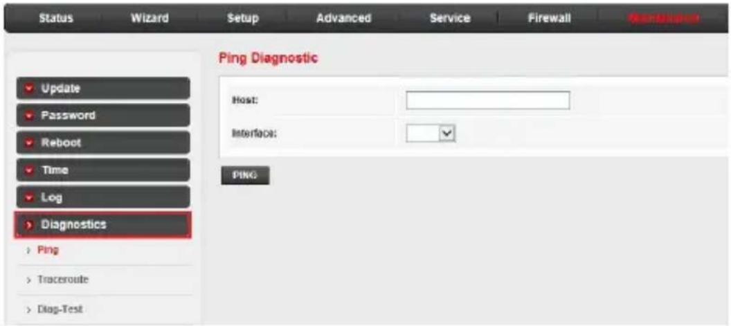
The router provides several useful diagnostic tools.
Click the Diagnostics sub-menu in the left pane. The Ping Diagnostic page opens. On this page, you can use the ping command to send a message to the host you specified.
Configure your router
Maintenance
Diagnostics: Traceroute
The router provides a trace route command to measure the route path and transit time of packets across an Internet Protocol (IP) network.
Click Traceroute in the left pane. The Traceroute Diagnostic page opens. On this page, you can specify an IP address or host to run trace route command.
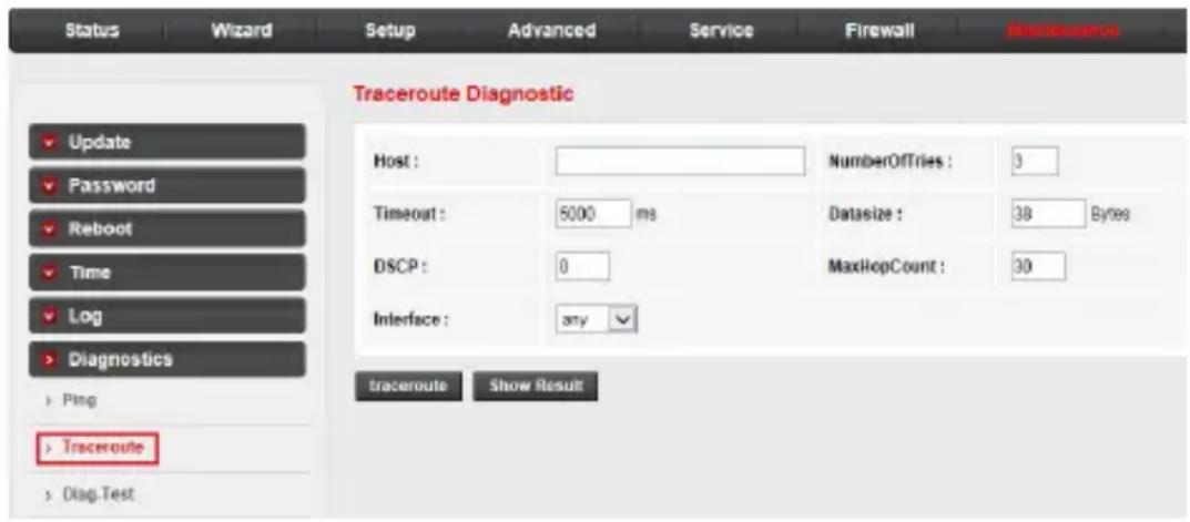
- Host: An IP address or host name you want to run trace route command.
• NumberofTries: The number of tries. - Timeout: The time for the trace route command timeout.
- Datasize: Data size of the trace route packet.
• DSCP: The value of DSCP. - MaxHopCount: The maximum hop count.
- Interface: The interface to which the trace route is to be applied.
Configure your router
Maintenance
Diagnostics: Diagnostic test
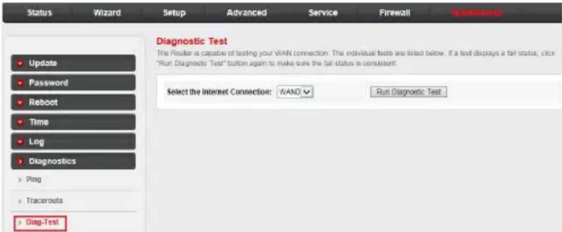
The Diagnostic Test allows you to test your DSL connection of the physical layer and protocol layer for both LAN and WAN sides.
Click Diag-Test in the left pane. The Diagnostic Test page opens. On this page, you can select an interface to run the diagnostic test.
Click the Run Diagnostic Test button to start the test. The test result will display after several minutes.
Appendix
Frequently asked questions
Below are the questions most frequently asked about the router. If you cannot find the answer to your question, visit our website at businessphones.vtech.com or call 1 (888) 370-2006 for customer service.
My router does not work.
- Make sure you install the router properly, and the electrical outlet is not controlled by a wall switch.
- Make sure the router is powered on and the light is on.
My router cannot load data from the Internet.
- Make sure you connect the WAN port properly. DO NOT mix up the WAN port with the LAN ports.
- Disconnect and then reconnect the power adapter, and then wait for a while for the router to restart. Observe the WAN light; it flashes when the router receives data.
- Disconnect the Ethernet cable from the router and connect it to a different router. If there is no signal on that router either, the problem is in your wiring or local service. Contact your Internet service provider.
- Your Ethernet cable might be defective. Try installing a new one.
How do I restore my router to its factory default settings?
- When the router is powered on, use a narrow-pointed object to press and hold the Reset button, and then wait for a while for the router to restart.

NOTE
- After the router resets to default settings, use the default user name and password to login to the web management page.
What can I do if I forgot my password?
- Restore the router to factory default settings. After the router restarts, use the default user name and password to log in to the web management page.
What can I do if my Ethernet devices cannot obtain IP addresses?
- Make sure you install the router and connect it with your Ethernet devices properly. See “Connect your system” on page 5 for details.
- If you have more than four Ethernet devices, use a narrow-pointed object to press and hold the Reset button, and then wait for a while for the router to restart.
Appendix
FCC part 15
This equipment has been tested and found to comply with the requirements for a Class B digital device under Part 15 of the Federal Communications Commission (FCC) rules. These requirements are intended to provide reasonable protection against harmful interference in a residential installation. This equipment generates, uses and can radiate radio frequency energy and, if not installed and used in accordance with the instructions, may cause harmful interference to radio communications. However, there is no guarantee that interference will not occur in a particular installation. If this equipment does cause harmful interference to radio or television reception, which can be determined by turning the equipment off and on, the user is encouraged to try to correct the interference by one or more of the following measures:
- Reorient or relocate the receiving antenna.
- Increase the separation between the equipment and receiver.
- Connect the equipment into an outlet on a circuit different from that to which the receiver is connected.
- Consult the dealer or an experienced radio/TV technician for help.
WARNING: Changes or modifications to this equipment not expressly approved by the party responsible for compliance could void the user's authority to operate the equipment.
This device complies with Part 15 of the FCC Rules. Operation is subject to the following two conditions: (1) this device may not cause harmful interference, and (2) this device must accept any interference received, including interference that may cause undesired operation.
This Class B digital apparatus complies with Canadian requirement: CAN ICES-3 (B)/NMB-3(B)
Appendix
For cETL compliance only
For cETL compliance only
1. What does this limited warranty cover?
The manufacturer of this VTech product warrants to the holder of a valid proof of purchase (“CONSUMER” or “you”) that the product and all accessories provided in the sales package (“PRODUCT”) are free from defects in material and workmanship, pursuant to the following terms and conditions, when installed and used normally and in accordance with the PRODUCT operating instructions. This limited warranty extends only to the CONSUMER for products purchased and used in the United States of America and Canada.
2. What will VTech do if the PRODUCT is not free from defects in materials and workmanship during the limited warranty period ("materially defective PRODUCT")?
During the limited warranty period, VTech's authorized service representative will repair or replace at VTech's option, without charge, a materially defective PRODUCT. If we repair the PRODUCT, we may use new or refurbished replacement parts. If we choose to replace the PRODUCT, we may replace it with a new or refurbished PRODUCT of the same or similar design. We will retain
defective parts, modules, or equipment. Repair or replacement of the PRODUCT, at VTech's option, is your exclusive remedy. VTech will return repaired or replacement products to you in working condition. You should expect the repair or replacement to take approximately 30 days.
3. How long is the limited warranty period?
The limited warranty period for the PRODUCT extends for TWO (2) YEARS from the date of purchase. If VTech repairs or replaces a materially defective PRODUCT under the terms of this limited warranty, this limited warranty also applies to repaired or replacement PRODUCT for a period of either (a) 90 days from the date the repaired or replacement PRODUCT is shipped to you or (b) the time remaining on the original two-year limited warranty; whichever is longer.
4. What is not covered by this limited warranty?
This limited warranty does not cover:
- PRODUCT that has been subjected to misuse, accident, shipping or other physical damage, improper installation, abnormal operation or handling, neglect, inundation, fire, water, or other liquid intrusion; or
- PRODUCT that has been damaged due to repair, alteration, or modification by anyone other than an authorized service representative of VTech; or
- PRODUCT to the extent that the problem experienced is caused by signal conditions, network reliability or cable or antenna systems; or
- PRODUCT to the extent that the problem is caused by use with non-VTech accessories; or
- PRODUCT whose warranty/quality stickers, PRODUCT serial number plates or electronic serial numbers have been removed, altered or rendered illegible; or
- PRODUCT purchased, used, serviced, or shipped for repair from outside the United States of America or Canada, or used for commercial or institutional purposes (including but not limited to products used for rental purposes); or
- PRODUCT returned without a valid proof of purchase (see item 6 on the next page); or
- Charges for installation or setup, adjustment of customer controls, and installation or repair of systems outside the unit.
Appendix
Limited Warranty
5. How do you get warranty service?
To obtain warranty service, visit businessphones.vtech.com or call 1 (888) 370-2006.
NOTE: Before calling for service, please review the user's manual; a check of the PRODUCT's controls and features may save you a service call.
Except as provided by applicable law, you assume the risk of loss or damage during transit and transportation and are responsible for delivery or handling charges incurred in the transport of the PRODUCT(s) to the service location. VTech will return repaired or replaced PRODUCT under this limited warranty to you. Transportation, delivery or handling charges are prepaid. VTech assumes no risk for damage or loss of the PRODUCT in transit. If the PRODUCT failure is not covered by this limited warranty, or proof of purchase does not meet the terms of this limited warranty, VTech will notify you and will request that you authorize the cost of repair prior to any further repair activity. You must pay for the cost of repair and return shipping costs for the repair of products that are not covered by this limited warranty.
6. What must you return with the PRODUCT to get warranty service?
You must:
- Return the entire original package and contents including the PRODUCT to the VTech service location along with a description of the malfunction or difficulty; and
- Include a "valid proof of purchase" (sales receipt) identifying the PRODUCT purchased (PRODUCT model) and the date of purchase or receipt; and
- Provide your name, complete and correct mailing address, and telephone number.
7. Other limitations
This warranty is the complete and exclusive agreement between you and VTech. It supersedes all other written or oral communications related to this PRODUCT. VTech provides no other warranties for this PRODUCT. The warranty exclusively describes all of VTech's responsibilities regarding the PRODUCT. There are no other express warranties. No one is authorized to make modifications to this limited warranty and you should not rely on any such modification.
State/Provincial Law rights: This warranty gives you specific legal rights, and you may also have other rights which vary from state to state or province to province.
Limitations: Implied warranties, including those of fitness for a particular purpose and merchantability (an unwritten warranty that the PRODUCT is fit for ordinary use) are limited to one year from date of purchase. Some states/provinces do not allow limitations on how long an implied warranty lasts, so the above limitation may not apply to you. In no event shall VTech be liable for any indirect, special, incidental, consequential, or similar damages (including, but not limited to lost profits or revenue, inability to use the PRODUCT or other associated equipment, the cost of substitute equipment, and claims by third parties) resulting from the use of this PRODUCT. Some states/provinces do not allow the exclusion or limitation of incidental or consequential damages, so the above limitation or exclusion may not apply to you.
Please retain your original sales receipt as proof of purchase.
Appendix
Technical specifications
Operating temperature 34^ F - 104^ F
0^-40^
Power requirements Input: 100-240V AC 500mA 50/60Hz
Output: 12V DC 1000mA
Network Ethernet ports 10/100 Mbps RJ-45 Ports
The Wi-Fi CERTIFIED™ Logo is a certification mark of Wi-Fi Alliance®.
VTECH COMMUNICATIONS LTD.
A member of THE VTECH GROUP OF COMPANIES.
Distributed in the U.S.A. by VTech Communications Inc., Beaverton, Oregon 97008.
VTech is a registered trademark of VTech Holdings Limited.
Copyright © 2016 for VTECH COMMUNICATIONS LTD. All rights reserved.
Version 1, 12/16
- businessphones.vtech.com
- vtech®
- User's manual
- Congratulations
- Important Safety Information
- SAVE THESE INSTRUCTIONS
- Electromagnetic fields (EMF)
- Parts checklist
- Table of Contents
- Important Safety Information ... i
- Parts checklist......ii
- Getting started ....3
- Configure your router ......13
- Appendix......65
- Getting started Router Overview
- 1- On/Off light
- 2- USB light
- 3- WAN light
- 4- Light
- 5- Wi-Fi light
- 6- light
- Getting started
- Router Overview
- 7-USB port
- 8-Power jack
- 9- On/Off button
- 10-LAN ports
- 11-WAN port
- 12-RESET button
- 13-WPS button
- Connect your system
- NOTES
- Configure your computer network
- For Windows XP/2000
- Select Obtain IP address automatically and Obtain DNS server address automatically, and then click OK.
- For Windows Vista/7/8
- Click Change adapter settings.
- Right-click Local Area Connection, and then select Properties.
- Select Internet Protocol Version 4 (TCP/IPv4), and then click Properties.
- Select Obtain an IP address automatically and Obtain DNS server address automatically, and then click OK.
- Connecting wireless devices
- Manual connection
- Using WPS
- Configure your router
- Log in to the web management page
- TIP
- NOTE
- Web management page overview
- Fast configuration
- Status
- Device info: Wireless Router Status
- Statistics
- Setup
- WAN: WAN Configuration
- LAN: LAN Interface Setup
- LAN: DHCP Static IP Configuration
- In the left pane, click DHCP Static. The DHCP Static IP
- WLAN: Wireless Basic Settings
- WLAN: Wireless Security Setup
- WLAN: Wireless Multiple BSSID Setup
- WLAN: Wireless Access Control
- WLAN: Wireless Advanced Settings
- WLAN: Wi-Fi Protected Setup
- WLAN: WDS Settings
- Advanced
- Route: Routing configuration
- Route: RIP Configuration
- NAT: DMZ
- NAT: Virtual server
- NAT: ALG
- NAT: NAT port trigger
- NAT: NAT IP mapping
- QoS: IP QoS
- QoS: IP QoS traffic shaping:
- Port Mapping Configuration
- To manipulate a mapping group:
- Others: Bridge Setting
- Others: Client limit configuration
- Others: Telnet
- Service
- UPnP
- DNS Configuration
- Dynamic DNS Configuration
- USB Storage
- To share files on a connected USB drive:
- Firewall
- MAC filter
- IP/Port filter
- IP/Port filtering (continued):
- URL filter
- DoS
- Maintenance
- Update: Upgrade firmware
- To upgrade the router's firmware:
- Configure your router Maintenance
- Click the Upload button.
- When the confirmation message appears, click OK to proceed.
- After the firmware file is uploaded, the system starts a 30-second countdown and then reboots. You need to login to the web management page again.
- Update: Backup/restore settings:
- To back up the router's current settings:
- To restore the router's current settings:
- Password: User account configuration
- To create an account:
- To change the password of an account:
- Reboot
- Time
- System time configuration:
- Log: Log setting
- Diagnostics: Ping
- Diagnostics: Traceroute
- Diagnostics: Diagnostic test
- Appendix
- Frequently asked questions
- My router does not work.
- My router cannot load data from the Internet.
- How do I restore my router to its factory default settings?
- What can I do if I forgot my password?
- What can I do if my Ethernet devices cannot obtain IP addresses?
- FCC part 15
- For cETL compliance only
- What does this limited warranty cover?
- What will VTech do if the PRODUCT is not free from defects in materials and workmanship during the limited warranty period ("materially defective PRODUCT")?
- How long is the limited warranty period?
- What is not covered by this limited warranty?
- Limited Warranty
- How do you get warranty service?
- What must you return with the PRODUCT to get warranty service?
- Other limitations
- Please retain your original sales receipt as proof of purchase.
- Technical specifications
Brand : VTECH
Model : VNT832
Category : Router