DN204P1V4 - Security Camera Digimerge - Free user manual and instructions
Find the device manual for free DN204P1V4 Digimerge in PDF.


| Product Type | Security Camera (IP) |
| Model | DN204P1V4 |
| Brand | Digimerge |
| Resolution | 4 MP (2592 x 1520) |
| Lens | 2.8 mm fixed lens |
| Field of View | 102° (horizontal) |
| Night Vision | IR LEDs up to 30 meters |
| Video Compression | H.265, H.264 |
| Power Supply | PoE (Power over Ethernet) IEEE 802.3af |
| Power Consumption | ≤ 5 W |
| Dimensions (W x H x D) | 70 x 190 x 70 mm |
| Weight | 0.5 kg |
| Ingress Protection | IP66 weatherproof |
| Operating Temperature | -30°C to 60°C |
| Mounting Type | Wall or ceiling mount |
| Main Features | Motion detection, remote viewing, microSD storage (up to 128 GB) |
| Maintenance | Clean lens with soft cloth; avoid solvents |
| Safety | UL listed; surge protection |
| Spare Parts & Repairability | Contact authorized service center; no user-serviceable parts |
| General Information | ONVIF compatible; 1-year warranty |
Frequently Asked Questions - DN204P1V4 Digimerge
User questions about DN204P1V4 Digimerge
0 question about this device. Answer the ones you know or ask your own.
Ask a new question about this device
Download the instructions for your Security Camera in PDF format for free! Find your manual DN204P1V4 - Digimerge and take your electronic device back in hand. On this page are published all the documents necessary for the use of your device. DN204P1V4 by Digimerge.
USER MANUAL DN204P1V4 Digimerge
DIGIMERGE | Right for Business
DNR200V Series
Network Video Surveillance Recorder
4 1080P View & Record CMS Mobile Apps HDMI H.264

natural_image
Black DigJMERGE server unit with ports and indicator lights (no readable text beyond branding)Instruction Manual
English Version 1.0
www.digimerge.com
Copyright © 2013 Digimerge Technologies Inc.
Thank you for purchasing this product. Digimerge is committed to providing our customers with a high quality, reliable security solution.
This manual refers to the following models:
- DNR200V Series
For more information on this product, firmware updates, and accessory products, please visit us at:
www.digimerge.com

CAUTION
RISK OF ELECTRIC SHOCK DO NOT OPEN

CAUTION: TO REDUCE THE RISK OF ELECTRIC SHOCK DO NOT REMOVE COVER. NO USER SERVICABLE PARTS INSIDE.
REFER SERVICING TO QUALIFIED SERVICE PERSONNEL.

The lightning flash with arrowhead symbol, within an equilateral triangle, is intended to alert the user to the presence of uninsulated "dangerous voltage" within the products' enclosure that may be of sufficient magnitude to constitute a risk of electric shock.

The exclamation point within an equilateral triangle is intended to alert the user to the presence of important operating and maintenance (servicing) instructions in the literature accompanying the appliance.
WARNING: TO PREVENT FIRE OR SHOCK HAZARD, DO NOT EXPOSE THIS UNIT TO RAIN OR MOISTURE.
CAUTION: TO PREVENT ELECTRIC SHOCK, MATCH WIDE BLADE OF THE PLUG TO THE WIDE SLOT AND FULLY INSERT.
Important Safeguards
In addition to the careful attention devoted to quality standards in the manufacturing process of your video product, safety is a major factor in the design of every instrument. However, safety is your responsibility too. This sheet lists important information that will help to assure your enjoyment and proper use of the video product and accessory equipment. Please read them carefully before operating and using your video product.
Installation
- Read and Follow Instructions - All the safety and operating instructions should be read before the video product is operated. Follow all operating instructions.
- Retain Instructions - The safety and operating instructions should be retained for future reference.
- Heed Warnings - Comply with all warnings on the video product and in the operating instructions.
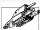
- Polarization - Do not defeat the safety purpose of the polarized or grounding-type plug.
A polarized plug has two blades with one wider than the other.
A grounding type plug has two blades and a third grounding prong.
The wide blade or the third prong are provided for your safety.

If the provided plug does not fit into your outlet, consult an electrician for replacement of the obsolete outlet.
- Power Sources - This video product should be operated only from the type of power source indicated on the marking label. If you are not sure of the type of power supply to your location, consult your video dealer or local power company. For video products intended to operate from battery power, or other sources, refer to the operating instructions.
- Overloading - Do not overload wall outlets of extension cords as this can result in the risk of fire or electric shock. Overloaded AC outlets, extension cords, frayed power cords, damaged or cracked wire insulation, and broken plugs are dangerous. They may result in a shock or fire hazard. Periodically examine the cord, and if its appearance indicates damage or deteriorated insulation, have it replaced by your service technician.
-
Power Cord Protection - Power supply cords should be routed so that they are not likely to be walked on or pinched by items placed upon or against them, paying particular attention to cords at plugs, convenience receptacles, and the point where they exit from the video product.
-
Ventilation - Slots and openings in the case are provided for ventilation to ensure reliable operation of the video product and to protect it from overheating. These openings must not be blocked or covered. The openings should never be blocked by placing the video equipment on a bed, sofa, rug, or other similar surface. This video product should never be placed near or over a radiator or heat register. This video product should not be placed in a built-in installation such as a bookcase or rack unless proper ventilation is provided or the video product manufacturer's instructions have been followed.
- Attachments - Do not use attachments unless recommended by the video product manufacturer as they may cause a hazard.
- Camera Extension Cables – Check the rating of your extension cable(s) to verify compliance with your local authority regulations prior to installation.
- Water and Moisture - Do not use this video product near water. For example, near a bath tub, wash bowl, kitchen sink or laundry tub, in a wet basement, near a swimming pool and the like. Caution: Maintain electrical safety. Powerline operated equipment or accessories connected to this unit should bear the UL listing mark of CSA certification mark on the accessory itself and should not be modified so as to defeat the safety features. This will help avoid any potential hazard from electrical shock or fire. If in doubt, contact qualified service personnel.
- Accessories - Do not place this video equipment on an unstable cart, stand, tripod, or table. The video equipment may fall, causing serious damage to the video product. Use this video product only with a cart, stand, tripod,
bracket, or table recommended by the manufacturer or sold with the video product. Any mounting of the product should follow the manufacturer's instructions and use a mounting accessory recommended by the manufacturer.

Service
- Servicing - Do not attempt to service this video equipment yourself as opening or removing covers may expose you to dangerous voltage or other hazards. Refer all servicing to qualified service personnel.
-
Conditions Requiring Service - Unplug this video product from the wall outlet and refer servicing to qualified service personnel under the following conditions:
-
When the power supply cord or plug is damaged.
- If liquid has been spilled or objects have fallen into the video product.
- If the video product has been exposed to rain or water.
- If the video product does not operate normally by following the operating instructions. Adjust only those controls that are covered by the operating instructions. Improper adjustment of other controls may result in damage and will often require extensive work by a qualified technician to restore the video product to its normal operation.
- If the video product has been dropped or the cabinet has been damaged.
-
When the video product exhibits a distinct change in performance. This indicates a need for service.
-
Replacement Parts - When replacement parts are required, have the service technician verify that the replacements used have the same safety characteristics as the original parts. Use of replacements specified by the video product manufacturer can prevent fire, electric shock or other hazards.
- Safety Check - Upon completion of any service or repairs to this video product, ask the service technician to perform safety checks recommended by the manufacturer to determine that the video product is in safe operating condition.
- Wall or Ceiling Mounting - The cameras provided with this system should be mounted to a wall or ceiling only as instructed in this guide, using the provided mounting brackets.
- Heat - The product should be situated away from heat sources such as radiators, heat registers, stoves, or other products (including amplifiers) that produce heat.
G
Use
- Cleaning - Unplug the video product from the wall outlet before cleaning. Do not use liquid cleaners or aerosol cleaners. Use a damp cloth for cleaning.
- Product and Cart Combination - Video and cart combination should be moved with care. Quick stops, excessive force, and uneven surfaces may cause the video product and car combination to overturn.
- Object and Liquid Entry - Never push objects for any kind into this video product through openings as they may touch dangerous voltage points or "short-out" parts that could result in a fire or electric shock. Never spill liquid of any kind on the video product.
- Lightning - For added protection for this video product during a lightning storm, or when it is left unattended and unused for long periods of time, unplug it from the wall outlet and disconnect the antenna or cable system. This will prevent damage to the video product due to lightning and power line surges.
General Precautions
- All warnings and instructions in this manual should be followed.
- Remove the plug from the outlet before cleaning. Do not use liquid aero sol detergents. Use a water dampened cloth for cleaning.
- Do not use this unit in humid or wet places.
- Keep enough space around the unit for ventilation. Slots and openings in the storage cabinet should not be blocked.
- During lightning storms, or when the unit is not used for a long time, disconnect the power supply, antenna, and cables to protect the unit from electrical surge.
FCC CLASS A NOTICE
NOTE
This equipment has been tested and found to comply with the limits for a Class A digital device pursuant to Part 15 of the FCC Rules. These limits are designed to provide reasonable protection against harmful interference when the equipment is operated in a commercial environment. This equipment generates, uses, and can radiate radio frequency energy and, if not installed and used in accordance with the manufacturer's instruction manual, may cause harmful interference with radio communications. Operation of this equipment in a residential area is likely to cause harmful interference, in which case you will be required to correct the interference at your own expense.
This equipment has been certified and found to comply with the limits regulated by FCC, EMC, and LVD. Therefore, it is designated to provide reasonable protection against interference and will not cause interference with other appliance usage.
However, it is imperative that the user follows the guidelines in this manual to avoid improper usage which may result in damage to the unit, electrical shock and fire hazard injury.
In order to improve the feature functions and quality of this product, the specifications are subject to change without notice from time to time.
DIG!MERGE
www.digimerge.com
Features

natural_image
Black server rack unit labeled 'MIOJMERGE' with ports and ventilation slots (no readable text beyond branding)- Easy Connection and setup with 4 integrated PoE ports and auto-discovery of IP Cameras
- Record all 4 cameras in Real-Time at 1080P Full HD quality
- Full HD 1080P recording provides the most detailed picture and reliable identification with selectable area digital zoom
- Dual streaming (H.264) and dual core processor
- Pentaplex operation - simultaneous View, Record, Playback, Backup & Remote Monitoring
• ONVIF 2.0 conformance ensures compatibility with popular industry IP cameras
- Substream recording for bandwidth efficient remote playback
• 64 Channel CMS by Digimerge included
• Fully PC / Mac compatible
• Mobile apps: iPhone, iPad, Android
• HDMI / VGA simultaneous video output
• Free DDNS service by Digimerge with secure redundant servers
• RS-485 supports Pelco D & P PTZ
• Audio I/O: 1 in - 1 out, Alarm I/O
• Supports 2x SATA HDDs up to 3TB (6TB total), 2x USB 2.0 ports
• eSATA back-up/storage up to 4 HDD (12TB total)
- Drive Mirroring
- Embedded Linux operating system, simple GUI on screen display
• 1/3/5 year Fortress Vision warranty
*Please visit www.digimerge.com for information, firmware, and compatibility updates for mobile viewing
TABLE OF CONTENTS
Getting Started .... 1
Basic Setup 2
- Connect the Cameras .... 2
- Connect a Monitor 2
- Connect the Mouse 2
- Connect the Ethernet Cable 2
- Connect the Power Adapters .... 2
Front Panel 3
Rear Panel 4
Remote Control.... 5
Mouse Control 6
Using the System 7
Password 7
On-Screen Display 7
Using the Quick Menu 8
Adjusting Color Settings 8
Using the Navigation Bar 9
Using the Camera Toolbar 9
Using Quick Playback 10
Using Digital Zoom in Live Display 10
Using Real-time Backup 10
Using the Virtual Keyboard 11
Setting the Time 12
Recording.... 13
Search (Playback).... 14
Playing Back Video from the Hard Drive 14
Playback Controls 15
Backup 16
Formatting the USB Device 16
Backing up Video 16
Using Video Clip Backup 17
Viewing Backup Files 18
Using the Main Menu 20
Info 21
HDD Info 21
BPS 21
Log 21
Version 21
Updating Firmware 21
Online Users 22
Remote Device Info 22
Setting 23
General 23
Recording 24
Schedule 24
Configuring the Recording Schedule 24
Configuring Pre-Recording and Mirror Recording 25
Configuring Holidays 25
Network 25
Configuring DHCP or Fixed IP Address 25
Configuring System Ports 25
Configuring NTP 26
Configuring DDNS 26
Configuring Email Alerts 27
Configuring Switch Settings 28
Motion 28
Configuring Motion Detection Events 28
Display 29
Default 30
Device Search 30
Adding Cameras from the LAN 30
Manual Add 31
Editing Cameras 31
Deleting Cameras 31
Advanced 32
HDD Management 32
Formatting Hard Drives 32
Selecting Hard Drive Types 32
Configuring Hard Drive Group Settings 32
Configuring eSATA External Hard Drives 33
Warning 34
Record 34
Account 35
Adding Accounts 35
Modifying Accounts ....36
Deleting Accounts 36
Adding Groups 36
Deleting Groups 37
Modifying Groups 37
Auto Maintain 37
Config Backup 37
Shutdown 38
DigiNet NVR Central Management Software 39
System Requirements 39
Prerequisites 39
Installing DigiNet NVR CMS 40
Adding a NVR from the Local Area Network (LAN) 40
Adding a NVR using a DDNS address 42
CMS Live Viewing Overview 44
Using Alarm Rec (Event Search) 45
Using Playback Mode ....46
Playback Controls 47
Configuring Monitoring Tasks and Projects 47
Configuring Tasks 47
Configuring Projects 48
Running Tasks and Projects 49
Using E-Map 50
Configuring E-Map 50
Opening Cameras from E-Map 51
Configuring the CMS 52
Configuring CMS Options 52
Changing the CMS Admin Password 53
Adding User Accounts to the CMS 54
Multi-Monitor Support 55
Opening Cameras in Secondary Monitors 55
Managing Secondary Monitors 55
Remote Viewing on Internet Explorer 57
Prerequisites 57
IE Live Display Overview 58
Using Search Mode in IE (Playback) 59
Playback Controls 60
Mobile Connectivity 61
iPhone 61
System Requirements 61
Prerequisites 61
Connecting to your NVR on an iPhone 61
DigiNet NVR Interface 63
Viewing Videos with Local File 63
Using Playback Mode on iPhone 64
Enabling Push Notifications 65
Device Manager 66
iPad 67
System Requirements 67
Prerequisites 67
Connecting to your NVR on an iPad 67
DigiNet NVR HDInterface 69
Device Manager 69
Using Playback Mode on iPad 70
Enabling Push Notifications 71
Android Phones 72
Compatible Devices 72
Prerequisites 72
Connecting to your NVR on an Android Phone 72
DigiNet NVR Interface 74
Viewing Snapshots and Videos with Local Files 75
Using Playback Mode on Android Phones 75
Enabling Push Notifications 76
Device Manager 78
Android Tablets 78
System Requirements 78
Prerequisites 78
Connecting to your NVR on an Android Tablet 79
DigiNet NVR HD Interface 80
Using Playback Mode on Android Tablets 81
Enabling Push Notifications 82
Device Manager 83
Appendix A: System Specifications 85
Appendix B: Setting up Remote Viewing 87
What Do I Need? 87
How Do I Find My IP and MAC addresses? 88
Finding Your External IP Address 88
How Do I Enable Port Forwarding? 88
Appendix C: Auto Port Forwarding Wizard 90
Installation 90
Obtaining Your Router Model Number and Version 91
Example 91
Configuration 91
Initial Startup: Select Language 92
Step 1: Populate the Router Database ....92
Step 2: Enter your Router Settings .....92
Step 3: Update the Router Settings .....94
Step 4: Test your Connection .....94
Configuring Multiple Routers 94
Scenario A: Router/Modem Combination + Router 95
Scenario B: Multiple Routers 95
Example 96
Appendix D: Setting Up DDNS Service 97
How Do I Enable DDNS On My System? 98
Connecting to your system using DDNS 99
CMS Software or Mobile Apps 99
Internet Explorer 99
Appendix E: Remote Firmware Upgrade 100
Installing a Firmware Upgrade Over the LAN 100
Installing a Firmware Upgrade Over the Internet 101
Appendix F: Hard Drive Installation.... 103
Installing a Hard Drive 103
Removing the Hard Drive 104
Formatting the Hard Drive 106
Troubleshooting 107
GETTING STARTED
The system comes with the following components:
a. Connect IP cameras to PoE (Power over Ethernet) ports. OR
b. Connect IP cameras to the same LAN as the NVR. For details on connecting IP cameras over the LAN, see "Device Search" on page 30.
2. Connect a Monitor
a. Connect an HDMI cable (not included) from the HDMI port on the rear panel to an HDTV or HDMI monitor, OR
b. Connect a VGA cable (not included) from the VGA port to the VGA port on your monitor.
3. Connect the Mouse
a. Connect the mouse (included) to one of the USB ports on the front or rear panel.
4. Connect the Ethernet Cable
a. Connect an Ethernet cable (not included) to the LAN port on the rear panel of system; connect the other end of the Ethernet cable to an empty LAN port on your router or switch (not included).
5. Connect the Power Adapters
a. Connect the DC 12V power supply to the DC 12V port on the rear panel of the system. Connect the power cable to an outlet, power strip, or surge protector. This power adapter is used to power the main unit.
b. Connect the DC 48V power supply to the DC 48V port on the rear panel of the system. Connect the power cable to an outlet, power strip, or surge protector. This power adapter is used to power the integrated PoE ports.
c. Turn the power switch to the ON position.

Connect IP cameras to the system

Connect to an HDMI, VGA, or BNC monitor

Connect the mouse to a USB port
Connect an Ethernet cable

Connect the power adapters
FRONT PANEL

- IR Receiver: IR receiver for the remote control. Keep the IR receiver clear from obstructions.
-
LED Indicators :
-
POWER ( ) ows to indicate the system is on.
- HDD (☐): Glows to indicate hard drive is in normal state. Turns off when there is a hard drive error.
- NET (☐): Glows when network is in normal state. Turns off for network error.
-
ALARM ( ▲): Glows when an external alarm or sensor device (not included) is triggered.
-
Power Button: Press and hold to power off the system. Press to power the system back on.
- FN: Performs special functions in some menus.
- USB Ports: Connect a USB mouse (included) or connect a USB flash drive (not included) for data backup or firmware upgrades.
REAR PANEL

-
PoE Ports: Camera input ports for IP cameras.
-
DC 48V: Port for 48V DC power supply (included) for integrated PoE ports.
-
Power Switch
-
eSATA Port: Connect a self-powered external eSATA HDD (not included) to extend the storage capacity of the system or for data backup. For details, see "Configuring eSATA External Hard Drives" on page 33.
-
VGA: V GA port to connect the system to a VGA monitor.
-
HDMI: HDMI port to connect the system to a HDMI TV/monitor.
-
ALARM IN / OU T / RS422-RS485: Alarm block to connect PTZ cameras (not included) or external alarm or motion devices (not included).
-
MIC:
• IN: RCA port for microphone (not included) for 2-way audio.
- OUT: RCA port for audio output device (e.g. speakers; not included) for 2-way audio.
-
NET: Connect an Ethernet c-able (not included) to connect the system to a router or switch (not included).
-
USB port: Connect a USB mouse or connect a USB flash drive (not included) for data backup or firmware upgrades.
- DC 12V: Port for 12V DC power supply (included).
- Ground
REMOTE CONTROL
- Power: Press and hold to power off the system. Press to power on.
-
Playback Contro ls:
-
Pause/Play: In live view, press to enter playback mode. Press to play/pause playback.
-
Reverse: Press to reverse playback/pause playback.
• Fast: Press to increase playback speed.
• Next: Press to skip to next video.
• Previous: Press to skip to previous video.
• Slow: Press for slow playback. -
Esc: In menus, press to go back / exit menus. In playback, press to return to live view.
- Directional Keys:
- Enter: Press once to open the System Information screen; press twice to open the Main Menu. Press to confirm menu selections.
- Press ◀ ▶ to move the menu cursor.
-
Press ▲▼ to change menu options.
-
Mult: Pr ess to switch between full-screen and split-screen layouts.
-
Number Keys:
-
1\~0: In live view, press to open channels in full-screen.
- In menus, press to input numbers or text input.
-
Shift: Press to change input types.
-
Add: Configure remote control address.
- Rec: Press to open manual record menu.
- Fn: Press to perform special functions in some menus.

Mouse Control
The mouse is the primary control device for the system. To connect a USB mouse:
- Connect a USB mouse to the USB port on the front or rear panel.
1. Left -Button:
• In live view, click to open the Navigation Bar.
- In live view, while in a split-screen display mode, double-click an individual channel to view it in full-screen. Double-click again to return to the split-screen display mode.
- While navigating menus, click to open a menu option.
2. Right-Button:
- During live view, right-click anywhere on the screen to open the Quick Menu.
-
Within navigating menus, right-click to exit menus.
-
Scroll-Wheel: Use to change menu options.

USING THE SYSTEM
The default system password is 000000
Password
By default, the login password is enabled. The default system password is 000000.
On-Screen Display
The system shows the following for all display views:
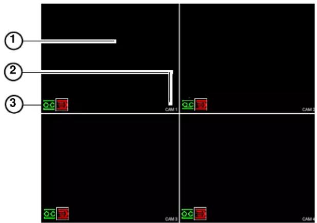
1. Display Area:
- Double-click on a channel to view in full-screen; double-click again to return to split screen.
- Right-click to open the Quick Menu. See "Using the Quick Menu" on page 8.
- Left-click to open the Navigation bar.
- Move the mouse to the top of a channel to view the Camera Toolbar.
- Click-and-drag cameras to rearrange the channel display. This does not affect the channels each camera is connected or recording to.
2. Channel Name
3. Channel Status Icons:
• channel is recording.
- Motion has been detected.
- Camera is locked (covert mode is activated).
Using the Quick Menu
The Quick menu gives you access to the system's key functions. To access the Quick Menu, right-click the screen during live view.

The Quick Menu has the following options:
- View: Select a camera in full-screen or select a multi-channel display.
- Pan/Tilt/Zoom: Access controls for PTZ cameras (not included).
• Color Setting: Configure color settings for IP cameras. - Search: Search/playback recorded video. See "Search (Playback)" on page 14.
- Record: Open the Record menu to select manual recording options. See “Recording” on page 24.
- Device Search: Open the Device Search menu to manage IP cameras.
- Alarm Output: Open the Alarm Output menu.
- Main Menu: Open the Main Menu. See "Using the Main Menu" on page 20.
Adjusting Color Settings
Use the Color Settings menu to adjust color settings for your IP cameras.
To adjust color settings:
- Right-click on the channel you would like to configure and select Color Setting. Enter the system password if prompted.
- Adjust the Hue, Brightness, Contrast, and Saturation settings that the camera will use. To enable custom Gain controls, check Gain and use the slider to configure the gain level.
OR
Use Color mode to select a preset color profile.

NOTE: Color settings will update once you save changes.
NOTE: To configure the Customized1\~4 profiles, click Customized.
- Click OK to save e changes.
Using the Navigation Bar
The Navigation Bar gives quick access to certain functions and menus.
To open the Navigation bar:
- Left click on the screen to open the Navigation Bar. The Navigation Bar has the following options:

Using the Camera Toolbar
The Camera Toolbar is used to perform actions on a specific channel.
To access the Camera Toolbar:
- Move the mouse to the top of the channel display. The Camera Toolbar has the following options:

Using Quick Playback
Quick Playback is used to playback the last 5\~60 minutes of video from the selected channel. You can also access Quick Playback in split-screen mode, while still viewing live video from the other channels.
To use Quick Playback:
- Move your mouse to the top of the e channel display and click
NOTE: By default, the NVR will begin playback from 5 minutes ago. You can increase this to up to 60 minutes using the Realtime Play setting in Main Menu→Setting→General.
- Right-click to exit Quick Playback.
Using Digital Zoom in Live Display
- Move your mouse to the top of the channel display and click 📄 to activate digital zoom. The icon will change to ✅ to indicate digital zoom is activated.
NOTE: You may activate digital zoom in multiple channels at the same time.
-
Click and drag inside the channel to zoom in.
-
Click and drag to pan the zoom area.
- Right-click to zoom out and select a new zoom area.
- Click 📋 to disable digital zoom. Note that the channel will remain at the same zoom level until you right-click inside it.
Using Real-time Backup
Real-time backup allows you to save footage from the live display to a USB flash drive (not included) or external hard drive (not included).
To use Real-time Backup:
- Insert the USB flash drive or external hard drive into one of the USB ports on the system.
- Move your mouse to the top of the e channel display and click to start Real-time Backup.
The icon changes to √.
- Click ☑ again to end Real-time Backup. The file is saved to your USB device.
NOTE: If the system prompts you to log in, you will need to click 📄 again to start Real-time Backup after logging in.
Using the Virtual Keyboard
The Virtual Keyboard is used to input text or numeric values in certain menus.

SETTING THE TIME

It is highly recommended to set the time on the system prior to doing any recording.
To set the date and time:
- In the main viewing mode, right-click and click Main Menu. Log into the system using the admin account (default User Name is admin and Password is 000000).
- Click Setting→General.
- Enter the current date (MM DD YYYY) and time (HH MM SS) under System Time.
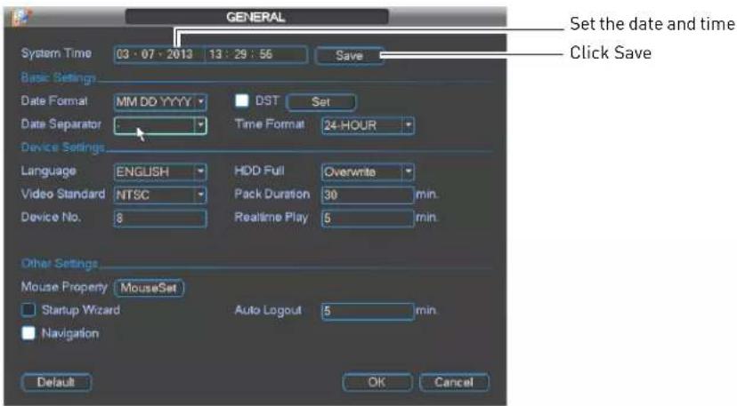
4. Click Save.
NOTE: To configure Daylight Savings Time see "General" on page 23. To configure NTP, see "Configuring NTP" on page 26.
RECORDING
By default, the system is set to immediately record at startup from connected cameras. This is called Continuous Recording. It is highly recommended to keep Continuous Recording on at all times.
The system supports the following recording types:
- Continuous Recording: By default, all camera channels are enabled with Continuous Recording. During Continuous Recording, the Record icon appears in the channel.
- Motion Recording: Cameras can be configured to record and mark events when motion is detected. When motion is detected, the Motion icon (E) appears in the channel.
NOTE: You must enable motion recording in the Schedule before the system will record motion events. For details, see "Schedule" on page 24.
- Alarm Recording: Cameras can be configured to record when external alarm devices are triggered.
SEARCH (PLAYBACK)
Search mode is used to navigate and playback recorded video files on the NVR.
Playing Back Video from the Hard Drive
-
From live view, right-click and then click Search. If needed, log in using the admin account (default User Name is admin and default Password is 000000).
-
Use the calendar on the right to select the day to playback.
-
Use the drop-down menus to select the channels you would like to playback. Click the display options (☐) to playback multiple channels simultaneously.
-
Click inside the video bar to select the playback time. The system will begin playing back at the selected time.

Click inside the bar to select a playback time
Playback Controls

Click inside the bar to select a playback time
BACKUP
Backup video files to external USB flash drive (not included) or self-powered USB external hard drive (not included).
NOTE: An eSATA external hard drive (not included) may also be used for backup. For details, see "Configuring eSATA External Hard Drives" on page 33.
Formatting the USB Device
It is recommended to format your USB device before using it with the system.
To format a USB device:

Formatting the USB device will permanently erase all data.
- Insert a USB flash drive (not included) or USB external hard drive (not included) into one of the USB ports.
- From live view, right-click and then select Main Menu. Login if prompted.
- Click Backup.
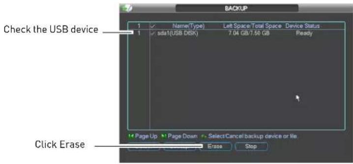
- Check the USB device you would like to format and click Erase. Click OK to confirm.
Backing up Video
- Insert a USB flash drive (not included) or USB external hard drive (not included) into one of the USB ports.
- From live view, right-click and then select Main Menu. Login if prompted.
- Click Backup.
- Check the USB device where you would like to save video.
5. Click Backup.

6. Configure your search options:

- Type: Select the recording type you would like to search for or select All to search all recording types.
- Channel: Select the channel you would like to search or select All to search all channels.
- File Format: Select DAV to save files to save files to .dav format. You can use the Player that is automatically saved on the USB device to playback .dav files on PC (Mac not supported). Or, select ASF for .asf format. You can playback .asf files in VLC Media Player (free download from www.videolan.org) on PC or Mac.
-
Start Time/End Time: Select the start and end time for your search.
-
Click Add. A list of files that match your search criteria appears.
-
Check files you would like to backup and then click Start. Wait for the backup to complete.
NOTE: HD video files saved on the system may take up a large amount of disk space. The size of video files selected and the amount of free space on your USB device is shown at the bottom of the screen.
Using Video Clip Backup
Video clip backup allows you to select a duration of video during playback mode and save it to a USB device (not included).
To use Video Clip Backup:
-
Insert a USB flash drive (not included) or USB external hard drive (not included) into one of the USB ports.
-
Start playing back video using the steps in "Playing Back Video from the Hard Drive" on page 14.
-
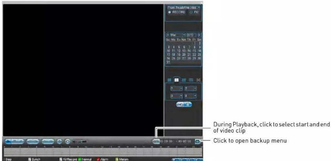
Click 📋 to mark the beginning of the video clip. Click 📋 again to mark the end of the video clip.
-
Click to open the Backup menu.
-
Check the USB device where you would like to save the file.
-
Check the files you would like to backup.

- Click Start. Wait for the backup to complete before removing the USB flash drive.
Viewing Backup Files
To playback .dav backup video files, use the Player that is automatically installed on the USB device when you save a backup file.
NOTE: The Player is PC compatible only. For Mac users, make sure to save backup files in .asf format (select ASF under File Format).
You can playback .asf backup video files in VLC Media Player (free download from www.videolan.org) on PC or Mac.
To view backup video files using the Player (PC only):
- Insert the USB device into your computer. Open the USB device in Windows Explorer.
-
Right-click the Play er.exe file and select Open as administrator. The Player opens and begins playing all video files on the USB device in sequence.
-
Use the Player controls to control playback or select other files for playback.

NOTE: To view or change where manual recordings or snapshots are saved, right click in the video area and select Parameter Setting.

USING THE MAIN MENU
To open the Main Menu:
• Using the Remote Control: Press the Enter button twice.
• Using the Mouse: Right-click and click Main Menu.
NOTE: The system password may be required to access the Main Menu. By default the User Name is admin and the Password is 000000.
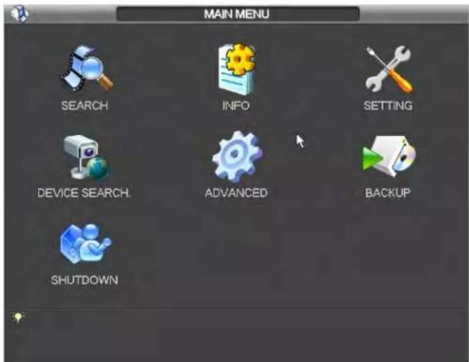
- SEARCH: Open Search/Playback mode. For details, see "Search (Playback)" on page 14.
- INFO: View system information. Perform firmware upgrades.
- SETTING: Configur e general system, schedule, network, recording, display, and motion settings. Restore system to factory defaults.
- DEVICE SEARCH : Connect IP cameras to the NVR.
- ADVANCED: Configur e HDD, user accounts, and error functions. Configure auto-restart. Save/restore system configuration. Access Manual Recording Menu.
- BACKUP: Export files to USB device. For details, see "Backup" on page 16.
- SHUTDOWN: Lo gout, restart, or shutdown the system.
NOTE: Checkboxes on the system are filled in white when settings are enabled or empty when disabled.
Info
The Info menu contains the following sub-menus showing system information.
HDD Info

The HDD Info sub-menu shows information related to the hard drives installed in the system, including capacity, status, and type. Click View recording time to see the start and end times of recordings saved on the hard drives.
BPS

The BPS sub-menu shows the bitrates of connected IP cameras.
Log
![LOG Type All Start Time 03 - 07 - 2013 00 00 : 00 End Time 03 - 08 - 2013 00 00 : 00 Details Search 17 Log Time Every 6 2013-03-07 13:15:26 Reboot with Flag [0x01] 7 2013-03-07 13:15:25 Save NETWORK Config? 8 2013-03-07 13:15:25 Disk totals<0>, Current working disk<-> 9 2013-03-07 13:18:23 DEFAULT 10 2013-03-07 13:18:23 Shut down at [03-07-13 13:16:16] 11 2013-03-07 13:18:23 Reboot with Flag [0x01] 12 2013-03-07 13:18:23 Disk totals<0>, Current working disk<-> 13 2013-03-07 13:21:55 Shut down at [03-07-13 13:20:55] 14 2013-03-07 13:21:55 Reboot with Flag [0x01] 15 2013-03-07 13:21:55 Disk totals<0>, Current working disk<-> 16 2013-03-07 13:21:55 User logged in 17 2013-03-07 13:22:35 Add Users Page Up Page Down Backup Clear PrePage NextPage M/(Current Page/Total Page) Jump to GO](/content/2026/05/1002354/images/8b3d2de963a035d2342de4a907d20f725eceffa8a1e4717279e61a1fa5bfd1f7.jpg)
The Log sub-menu allows you to search for system logs.
To search for system logs:
- Under Typ e, select the log type to search for.
- Under Start Time and End Time, select the start and end time for your search.
- Click Search.
- (Optional) Click Backup to export logs to a USB flash drive connected to the system.
Version

The Version sub-menu allows you to view information about the current firmware. You may also update the firmware through the version menu.
Updating Firmware
-
Download the latest firmware update from www.digimerge.com.
-
Copy the firmware to a blank USB flash drive.
NOTE: Do not have any folders on the USB flash drive—just the firmware file.
- Connect the USB flash drive to a USB port on the system.
- Right-click and then select Main Menu→Info→Version.
- Click Start to update firmware. Wait for the firmware upgrade to complete. Do not remove the USB flash drive until the upgrade process is complete or power off the NVR during the upgrade process.
Online Users

The Online Users sub-menu shows a list of users connected to the system using remote devices. You may Disconnect a user for up to 18 hours or Block a user from the system.
Remote Device Info
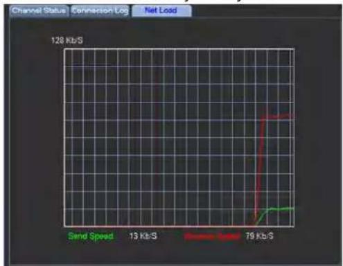
The Remote Device Info sub-menu shows information about IP cameras connected to the system, it contains the following tabs:
- Channel Status: Shows the IP address, model number, and camera status.
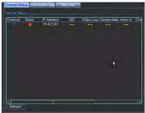
- Connection Log: Search for camera status logs, including user access to cameras.

- Net Load: Shows a graph of upload and download traffic for your system.
line
| Time (Gb/s) | Signal (Kb/S) | |-------------|---------------| | 79 | 128 |
Setting
The Setting menu allows you to configure general system, schedule, network, recording, display, and
motion settings. It also allows you to restore the system to factory defaults.
General

The General sub-menu allows you to Configure the time and general system settings.
The General sub-menu contains the following options:
- System Time: Select the current date and time and click Save to save changes.
- Date Format: Select the date format (YYYY MM DD, MM DD YYYY, or DD MM YYYY).
- Date Separator: Select if you would like a dot (.), dash (-), or slash (/) to separate the date display.
- DST: Check to enable daylight savings time adjustments. To configure the start and end times for daylight savings, click Set. Then, configure the Start and End as needed, and click OK.
• Time Format: Select 24-HOUR or 12-HOUR. -
Language: Select the system language.
• Video Standard: Select NTSC (North America) or PAL (Europe). -
Device No.: Select the Remote control ID for the NVR.
- Device ID: Enter a custom name for the NVR.
- HDD Full: Select Overwrite for the system to begin overwriting the oldest recordings when the hard drive is full or select Stop Recording for the system to stop recording when the hard drive is full.
- Pack Duration: Enter the desired pack duration. The pack duration determines the duration of video files saved to the system.
- Realtime Play: Select the duration of videos that will be played back in Quick Playback mode. For example, if Realtime Play is set to 5 minutes, Quick Playback will start playing back video recorded from 5 minutes ago on the selected channel.
- Mouse Property: Click MouseSet, adjust the double-click speed and click OK.
- Startup Wizard: Check to enable the Startup Wizard when your system starts. It is recommended to disable Startup Wizard once you have configured the system.
- Navigation: Check to enable the System Toolbar that appears when left clicking on the screen.
- Auto Logout: Enter the amount of time the system will wait before logging a user out when idle.
- IPC Time Sync: The NVR will regularly sync the internal clocks of connected IP cameras. Enter the interval between time syncs.
NOTE: Click OK when finished making changes.
Recording

The Recording sub-menu allows you to configure image quality settings for the recording stream and sub-stream (used during remote connection). Settings for the recording stream are shown on the left, and sub-stream settings are shown on the right.
To configure recording quality settings:
- Under Channel, select the channel you would like to configure.
- Under Ty pe, select the type of recording you would like to configure: Regular (continuous recording), MD (motion detection recording), or Alarm.
- Under Resolution, select the resolution for the selected recording type. Settings available depend on the model of IP camera connected.
- Under Fra me Rate, select the frame rate for the selected recording type on the left. Select the frame rate for the sub-stream on the right.
- Under Bit Rate Type, select CBR (Constant Bit Rate) or VBR (Variable Bit Rate) for the selected recording type on the left and sub-stream on the right. If you select VBR, select the Quality from 1 (lowest) to 6 (highest).
- Under Bit Rate (Kb/S), select the bit rate for the selected recording type on the left and the sub-stream on the right.
- Under Audio/Video, check the box on the left to enable audio recording (camera must have microphone attached). Check the box in the middle to enable audio
streaming to remote users. Check the box on the far right to enable video streaming to remote users (un-check to hide the channel from remote users.
- (Optional) To copy settings to other channels, click Copy, select channels to apply settings to, and click OK.
- Click OK to save changes.
Schedule

The Schedule sub-menu allows you to configure the recording schedule for continuous and motion recording. It also allows you to configure holiday, pre-recording, and redundancy settings.
NOTE: To use motion recording, motion detection must be enabled for the channel. For details, see "Motion" on page 28.
Configuring the Recording Schedule
- Under Channel, select the channel you would like to configure or select All.
- Under Period, select the day of the week you would like to configure, or select Holiday or All.
- Configure up to 6 separate schedule periods.
- Configure the start and end time for the time period on the left.
-
Check the types of recording that will apply to the time period on the right: Continuous, MD (Motion Detection), Alarm, or MD&Alarm.
-
A visual representation of the current schedule is shown below.
- (Optional) Click Copy to copy the selected to schedule to other channels. Select the channels you would like to copy to and click OK.
- Click OK to save e changes.
Configuring Pre-Recording and Mirror Recording
Pre-recording determines the amount of time the system will record before events. Mirroring allows the camera to record simultaneously to a secondary mirror hard drive and primary recording hard drive.
NOTE: Secondary hard drive must be installed and configured for mirror recording to use mirror recording function.
To configure pre-recording and mirror recording:
- Under Channel, select the camera you would like to configure or select All.
- Under PreRecor d, select the duration for pre-recording.
- Check Mirrori ng to enable mirror recording for the selected channel.
- Click OK to save e settings.
Configuring Holidays
Holiday settings allow you to configure a special recording schedule on certain days.
To configure holidays:
- Check the checkbox next to Holidays Setting to enable holidays.
- Click Holidays Setting.
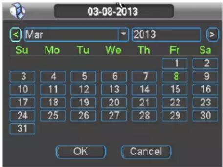
- Click days in the calendar to enable them as holidays. Selected holidays are highlighted in blue.
- Click OK. Click OK to save changes.
Network
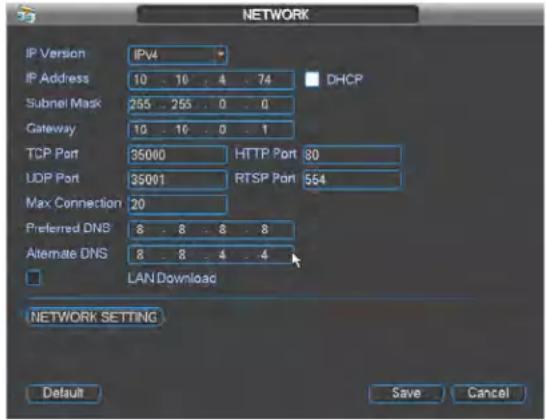
The Network sub-menu allows you to configure network settings.
Configuring DHCP or Fixed IP Address
- From live view, right-click and select Main Menu. Login if prompted.
- Click Setting→Network.
-
Check DHCP to use DHCP or un -check to use a static IP address. If you un-check DHCP, configure the following:
-
IP Address
- Subnet Mask
- Gateway
- Preferred DNS
-
Alternate DNS
-
Click Sav e to save your changes. Restart the system to update the IP address.
Configuring System Ports
The system uses the following ports:
- TCP Port (Client Port): Used for remote video streaming to computers and mobile devices. The default port number is 35000.
- HTTP Port: Used to enable connection to the system's web browser interface. The default port number is 80.
- UDP Port: Used for special applications. The default port number is 35001.
- RTSP Port: Used for special applications. The default port number is 554.
You must port forward the TCP (Client) Port and HTTP Ports to enable remote access to the system.
To configure ports:
- Configure the TC P Port (Client), HTTP Port, UDP Port, and RTSP Port fields as needed.
NOTE: Please note that if the HTTP is port is anything other than 80, you must enter http:// before the camera's IP address and colon (:) and the HTTP port after the IP address when connecting using an Internet browser (e.g. if the HTTP port is 85, enter http://192.168.x.x:85).
- Click Save. The system will restart to update the ports used.
Configuring NTP

You can sync the system clock with an Internet NTP time server.
To sync the system with a time server:
- Click Network Setting g.
- Check NTP.
- Double-click NTP to open the configuration menu.
- Configure the following:
- Under Server IP, enter the IP or DNS address of the NTP server.
- Under Port, enter the NTP server port number.
- Under Time Zone, select your time zone.
- Under Update Period, enter the interval your system will sync the time with the selected server.
TIP: Click Manual Update to test the server settings entered and manually sync the system time.
- Click OK. Click Sa ve to save your changes.
Configuring DDNS
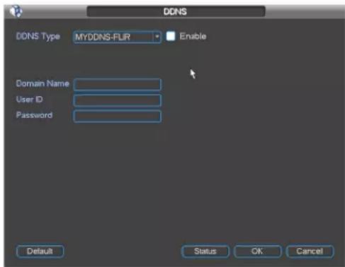
The DDNS Setup window allows you to enter your Digimerge DDNS settings in the NVR. This step is required for remote access.
Prerequisites:
- Create a DDNS account. For details, see "Appendix D: Setting Up DDNS Service" on page 97.
- Port forward ports on your router to NVR's IP address (by default, ports 35000 and 80).
- Have your DDNS account name, password, and domain name ready.
To configure DDNS settings:
- Click Network Setting.
- Check DDNS.
- Doubl e-click DDNS.
- Ensure Enable is checked. The box will be white when DDNS is enabled.
-
Under Domain Name, enter the Domain Name from the confirmation email you received after registering for DDNS.
-
Under User ID, enter the User Name from the confirmation email.
- Under Pass word, enter the Password from the confirmation email.
- Click OK.
- Click OK.
- Click Save.
Connecting to your system
After you have port forwarded the required port, created a DDNS account, and enabled DDNS on your system, you must enter the DDNS URL into Internet Explorer to access your NVR.
The DDNS URL must include http://, the name of your DDNS URL, followed by a colon, then the port number of your NVR.
For example:

NOTE: If you change your HTTP port number (port 80) to a different port, you must enter your port number after the DDNS address.
Configuring Email Alerts
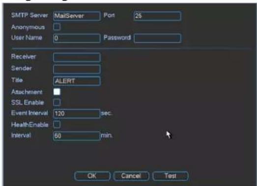
You can configure the system to send out email alerts for motion detection or other events.
NOTE: To send out motion detection alerts, you must enable the Send Email option for motion detection on each camera. For details, see "Configuring Motion Detection Events" on page 28.
To configure Email Alerts:
- From live view, right-click and select Main Menu. Log in if prompted.
- Click Setting→Network.
- Click Network Setting.

- Check Email. Double-click Email.

- Configure the following:

- SMTP Server: Enter the SMTP server address.
- Port: Enter the port used by the SMTP server.
- Anonymous: Check if your server supports anonymous log ins. Otherwise, leave this unchecked.
- User Name: Enter the SMTP user name.
- Password: Enter the SMTP password.
- Receiver: Enter the email address that will receive alerts.
- Sender: Enter the sender's email address.
- Attachment: Check to include a jpg image attachment of the camera.
- Title: Enter the subject line for email alerts.
- Encrypt Type: Select SSL or TLS if your server uses encryption. Select None if your server does not use encryption.
- Event Interval: Enter the interval between alert emails.
- Health Enable: Check to enable health check emails. Health check emails will be sent periodically to ensure that the system is functioning normally.
-
Interval: Enter the interval in minutes for health check emails.
-
Click Test to send a test email.
- Click OK.
- Click Save to save settings.
Configuring Switch Settings

You can configure the networking settings for
the internal PoE switch.
NOTE: Changing this information from the default values may disrupt the connection to the cameras. Make sure your IP cameras are using DHCP or IP addresses that are compatible with your selected settings.
To configure switch settings:
- Click Network Setting.
- Double-click Switch Settings.
- Configure the IP Add ress, Subnet Mask, and Gateway for the internal PoE switch.
- Click OK. Click Sa ve to save changes. The system will restart.
Motion
The Motion sub-menu allows you to configure settings for motion detection.
Configuring Motion Detection Events
Motion Detection events allow the system to mark footage that has motion. This allows you to quickly locate relevant footage through Search. You can also configure system responses to motion detection events, such as activating the system buzzer or sending an email alert.
To configure Motion Detection events:
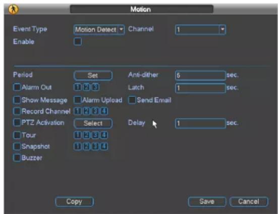
- Under Event Type, select Motion Detect.
- Under Channel, select the channel you would like to configure.
-
Check Enable to enable motion detection on the selected channel.
-
Under Sensitivity, select the motion detection sensitivity between 1 (lowest) and 6 (highest).
- Under Anti-dither, enter the anti-dither time. After a motion event occurs and motion stops, if motion is detected within the anti-dither time, the system continues the motion event and includes the new motion within the first event, rather than creating a new motion event.
- Under Delay, enter the post-recording time.
- To configure a schedule when motion detection will be enabled on this channel, click Set next to Period. Configure times when motion detection will be enabled. For example, you may want to disable motion detection during business hours and enable it outside of business hours. Click OK when finished.
NOTE: This setting can override scheduled motion recording. This means that motion recording will only take place at times that are enabled both in the Schedule menu and here.
-
Configure the following system actions when motion is detected:
-
Show Message: Check to enable an on-screen pop-up. On-screen pop-up shows the channels an event occurred on and the type of event.
- Send Email: Check to enable email alerts. You must configure email alerts before you will be able to receive them (see "Configuring Email Alerts" on page 27).
- Record Channel: Select the channels that will record when motion is detected on the selected channel.
- Buzzer: Check to enable the system buzzer.
-
Snapshot: Unsupported.
-
Click Sav e to save changes.
Display
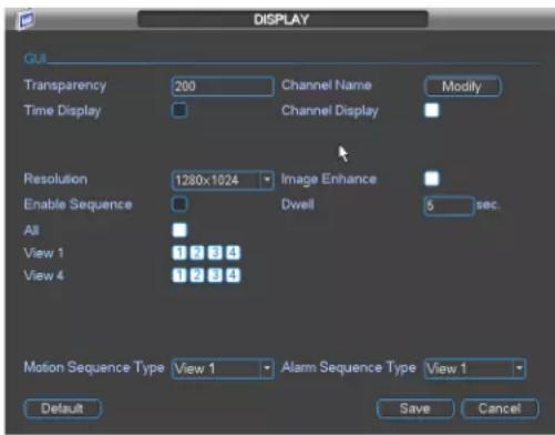
The Display sub-menu allows you to configure the system's display settings, such as the monitor resolution.
To configure display settings:
-
Configure the following, as needed:
-
Transparency: Select the menu transparency between 128 (lowest) and 255 (highest).
- Channel Name: Click Modify and enter names for your IP cameras. Click Save when finished.
- Time Display: Check to enable system time display.
- Channel Display: Check to enable camera title display.
- Resolution: Select the correct resolution for your monitor. The system will reboot when you save changes.
- Image Enhance: Check for the NVR to digitally improve the video quality on the live display. This setting does not affect recordings.
- Enable Sequence: Check to enable Sequence mode. When Sequence mode is activated, the system will cycle through enabled views and a (arrows) icon is shown on screen. You can click this icon to pause Sequence mode.
NOTE: View 1/View 4: Check to enable views to be shown in Sequence mode. View 1 allows you to enable/disable specific channels in Sequence mode. Other View
options allow you to enable/disable views based on pages.
- Dwell: Enter the Dwell time in seconds. The Dwell time is the amount of time views are shown on screen before changing in Sequence mode.
- Click Save to save changes.
Default

The Default sub-menu allows you to reset the system to factory default settings.
NOTE: Resetting to factory defaults does not reset user accounts or passwords.
To reset the system to factory default settings:
- Check the settings you would like to reset to default settings.
- Click OK.
Device Search
The Device Search menu allows you to manage connections to your IP cameras. SyncrolP cameras connected to the PoE (Power over Ethernet) Ports will automatically be detected by your NVR. Device Search also allows you to search for IP cameras connected to the LAN. Some configuration may be required to connect IP cameras from other manufacturers.
NOTE: For a list of 3rd party IP cameras supported, visit www.digimerge.com.
Adding Cameras from the LAN
- Connect the camera to a router or switch on the same network as the NVR.
- Right-click and select Device Search. Log in using the admin account (the default User Name is admin and the default Password is 000000).
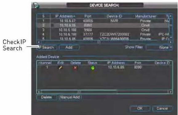
- Click IP Search. The NVR scans your LAN for compatible IP cameras.
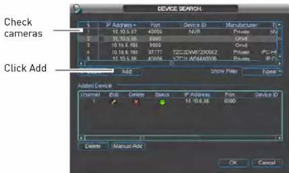
- Check the camera(s) you would like to add and click Add.
-
If the Status indicator is green, the camera is connected and no further configuration is required. Click OK to save changes.
-
If the Status indicator is red, click Update the following information needed.

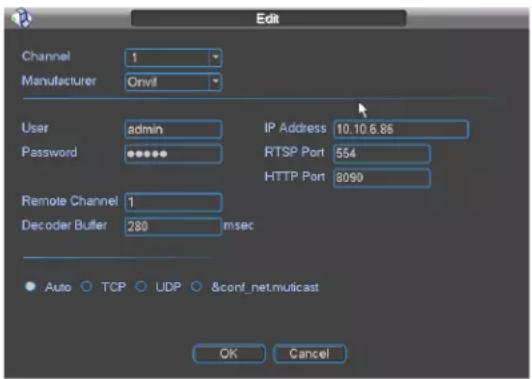
- Manufacturer: Select the manufacturer of your IP camera.
- User: Enter the camera's user name.
- Password: Enter the camera's password.
- RTSP Port: Enter the camera's RTSP Port.
- HTTP Port: Enter the camera's HTTP Port.
NOTE: See the manufacturer's user manual for your IP camera for the default user name, password, etc.
- Click OK. Click OK again to save changes.
Manual Add

If the IP address of your IP camera does not appear when you run IP search, ensure that the camera is connected to the same LAN as
the NVR or is connected to the PoE Ports. You may attempt to manually connect IP cameras using Manual Add.
To manually add a camera to the NVR:
-
Click Manual Add. Configure the following:
-
IP Address: Enter the public IP address of your IP camera.
- Manufacturer: Select the manufacturer of your IP camera.
- User: Enter the camera's user name.
- Password: Enter the camera's password.
- RTSP Port: Enter the camera's RTSP Port.
- HTTP Port: Enter the camera's HTTP Port.
NOTE: See the manufacturer's user manual for your IP camera for the default user name, password, etc.
- Click OK. Click OK again to save changes.
Editing Cameras
If the Status indicator on cameras connected to the NVR via PoE or LAN is red or if you change the connection details for your IP cameras, you will need to update this information.
To edit cameras:
- Click 📋 next to the camera you would like to edit.
- Configure the connection in formation as needed.
- Click OK. Click OK again to save changes.
Deleting Cameras
- Click next to the camera you would like to delete.

Advanced
Configure HDD, user accounts, and error functions. Configure auto-restart. Save/restore system configuration. Access Recording Menu.
HDD Management
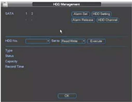
HDD Management allows you to format hard drives and manage hard drive settings. The top right corner shows hard drive status.
• 0: Normal hard drive operation.
• X: Hard drive error.
- -: Hard drive is not installed.
Formatting Hard Drives
You must format hard drives before you may use them with the system.
ATTENTION: Formatting the HDD erases all data on the hard disk. This step cannot be undone. System settings will not be erased.
To format a hard drive:
- From Live View, right-click and select Main Menu→Advanced→HDD Management.
- Under HD D No., select the hard drive you would like to format. Information about the hard drive appears in the lower section of the menu.
-
Under Set to, select Format.
-
Click Apply. Click OK to confirm. Wait for the hard drive to format. Hard drives become Read/Write hard drives by default when formatted.

Selecting Hard Drive Types
The system supports the following hard drive types:
- Read/Write: Normal recording hard drive.
- Read only: Do not record on the hard drive.
- Mirroring: Record in parallel to Read/Write hard drive for cameras enabled for mirroring. This allows you to create automatic backups of recordings.
NOTE: Mirroring must be enabled in the schedule (for details, see "Schedule" on page 24).
NOTE: Mirroring begins backing up data starting when the hard drive is configured for mirroring.
To select hard drive types:
- Under HDD No., select the hard drive you would like to format.
- Under Set to, select the hard drive type.
- Click Execute.
- Right-click to exit the HDD Management menu. The system will restart.
Configuring Hard Drive Group Settings
Hard drive group settings allows you to balance recordings for your IP cameras across multiple hard drives.
To configure hard drive group settings:
-
Click HDD Setti ng.
-
Under HDD Group select the group number you would like to assign to each hard drive.

-
Click OK. The system will restart.
-
Return to the HDD Manage menu (right-click→Main Menu→Advanced→HDD Manage). Click HDD Channel.
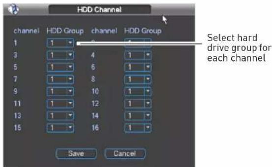
-
For each channel, select the hard drive group you would like it to record to.
-
Click OK.
Configuring eSATA External Hard Drives
You may use up to 4 eSATA external hard drives (up to 3TB each for a maximum capacity of 12TB; not included) by connecting a single, self-powered eSATA hard drive enclosure (not included) to the eSATA port on the system.
eSATA hard drives may be used for backup, recording, or mirroring hard drives. This is useful because you can store your external hard drive in a separate lock box from the main NVR unit.
To configure eSATA hard drives:
-
Connect an eSATA external hard drive to the eSATA port on the rear panel of the system.
-
From live view, right-click and click Main Menu. Log in if prompted.
-
Click Advanced→HDD Management.
NOTE: When eSATA HDD's are detected, they are located below the internal SATA HDD's. If they are not detected, restart the NVR.
- Click eSATA.
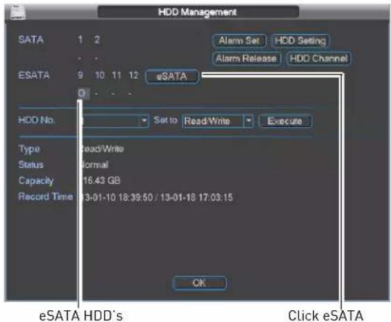
- Double-click on the hard drive you would like to configure.
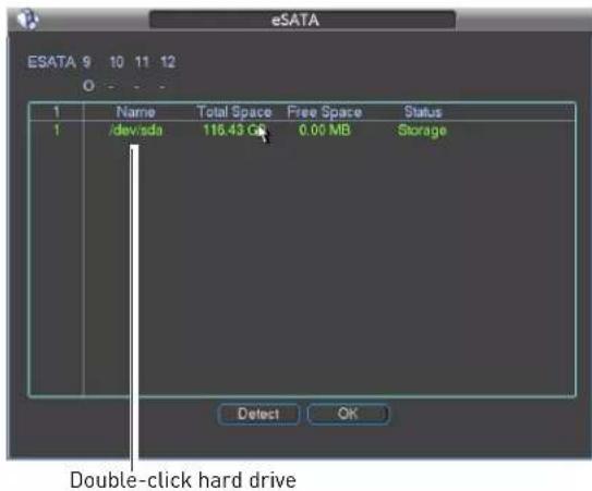
- Select Storage to use the hard drive for normal recording or mirroring or select
Backup to use the hard drive for data backup only. Click OK.
ATTENTION: This step will format the hard drive. Formatting the HDD erases all data on the hard disk. This step cannot be undone.

- The NVR formats the hard drive and restarts. If you set the external hard drive for Storage, you may configure it for Mirroring or Read only mode the same way you would configure one of the internal hard drives (see "Selecting Hard Drive Types" on page 32).
Warning

The Warning sub-menu allows you to configure actions taken when system errors occur.
To configure system error actions:
-
Under Event Type, select one of the following system errors to configure: No Disk, Disk Error, Disk No Space, Net Disconnection, IP Conflicted, or MAC Conflicted.
-
Check Enabl e to enable warnings for the selected Event Type.
-
Configure the following actions that will be taken when errors occur:
-
Show Message: Check to show pop-up window with information related to the error.
- Send Email: Check to enable email message. You must configure email alerts before you will be able to receive them.
-
Buzzer: Check to enable system buzzer.
-
Click Sav e to save changes.
Record

The Record menu is used control manual recording for connected cameras.
The Record menu is divided into the following sections.
- The Record Mode section defines settings for the main (high quality) recording stream.
- The Extra Stream section defines settings for an optional lower quality recording stream. This is useful because you can record the Extra Stream to the hard drive and stream it for playback to remote
devices. This saves bandwidth during remote playback.
NOTE: Enabling Extra Stream Recording is required to use playback mode on a smartphone or tablet.
NOTE: Recording the Extra Stream will increase the amount of disk space required for recording.
To configure manual recording:
- Right-click in live view and select Record. Log in if prompted.
OR
Click Main Menu→Advanced→Record. Log in if prompted.
-
Under Recor d Mode, select the main stream recording option under each camera or under All to configure all cameras:
-
Schedule: Camera will record according to settings configured in the schedule.
- Manual: When selected, the camera will use continuous recording.
-
Stop: When selected, the camera will not record.
-
Under Extra Stream, configure recording options for the Extra Stream.
-
Click OK to save e changes.
Account

The Account sub-menu allows you to configure user accounts. Accounts are organized into groups, and receive permission to access system functions based on their group's settings. By default, the following user groups are configured on the system:
- admin: Accounts in the admin group are system administrators. They have full access to the system, may configure all system settings, and can manage user accounts.
- user: Accounts in the user group are normal users. They have limited access to system menus.
Adding Accounts
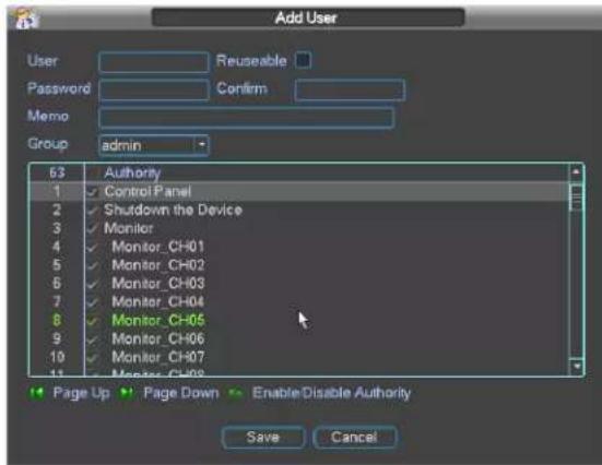
- Click Add User.
-
Configure the following:
-
User: Enter a user name for the account.
- Memo (Optional): Enter comments for the account.
- Password: Enter a password for the account. Repeat password under Confirm.
- Reusable: Check to enable multiple users to connect using this account.
-
Group: Select the group that the account will be included in.
-
In the bottom portion of the screen, select the permissions that will apply to the user. By default the account will have all permissions that are enabled for its group. An account cannot have more permissions than its group.
-
Click Save to save e changes.
Modifying Accounts
Admin accounts may modify the user name, password, and permissions of user accounts. User accounts may modify their own password.
To modify account settings:
-
Click the account in the list.
-
Click Modify User.

- Under User, select the account you would like to modify.
- Configure the account settings and permissions as necessary and then click Save.
To modify an account password:
- Click Mo dify Password.

- Under User, select the account you would like to modify.
- Under Old P password, enter the account's previous password.
- Under New P password, enter the new password for the account. Repeat it under Confirm.
- Click Save.
Deleting Accounts
- Click the account in the list.
- Click Modify User.
- Under User, select the account you would like to delete.
- Click Dele te then click OK to confirm.
Adding Groups
Groups allow you to easily manage permissions for multiple user accounts. A user account by default has all permissions available to the group it is in, and it cannot be given permissions the group does not have.
To add a group:
- Click Add Group.

- Under Name, enter a name for the group.
- (Optional) under Memo, enter comments for the group.
- Configure group permissions as needed. Note that any user accounts added to the
group may not be given any permissions that are not selected.

- Click Save.
Deleting Groups
- Click Modify Group.
- Under Group, select the user group you would like to delete.
- Click Dele te and then click OK to confirm.
Modifying Groups
- Click Modify Group.
- Under Group, select the user group you would like to modify.
- Update group settings as needed and then click Save.
Auto Maintain

The Auto-Maintain sub-menu allows you to configure your NVR to automatically reboot once a day or once a week. For system stability, it is recommended to enable auto-rebooting.
The Auto-Maintain sub-menu also allows you to set the NVR to automatically delete files that are older than a specified number of days.
To configure Auto Maintain settings:
- Under Auto-Reboot System, select the day of the week you would like the system to reboot on, select Everyday to reboot the system everyday, or select Never to disable auto-rebooting. On the right, select the time of day you would like the system to reboot.
- Under Auto-Delete Old Files, select Never to disable auto-deleting of old recordings or select Customized to enable auto-deleting.
- If you select Customized, enter the number of days the system will retain recordings.
NOTE: The system must have sufficient storage space to keep recordings for the specified duration.
- Click OK to save changes.
Config Backup
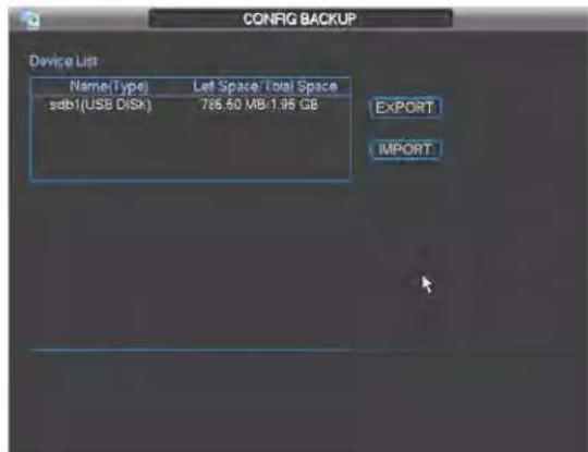
The Config Backup sub-menu allows you to export your system configuration to a USB flash drive (not included) or to import a saved configuration. You can import a saved configuration from another NVR of the same model and channel configuration.
To export the system configuration to a USB flash drive:
- Insert a USB flash drive into one of the USB ports on the system.
- Right-click and select Main Menu→Advanced→Config Backup.
- Check the USB flash drive you would like to export to in the list.
4. Click Export.
To import a saved system configuration:
- Insert a USB flash drive with a saved system configuration into one of the USB ports on the system.
- Right-click and select Main Menu→Advanced→Config Backup.
- Check the USB flash drive with the saved system configuration file.
- Click Import.
- Click OK. The system will restart.

Shutdown
Use the Shutdown menu to shutdown, restart, or log out of the system.
To access the Shutdown menu:
- From live view, right-click and select Main Menu. Login if prompted.
- Click Shutdown.
- Select one of the following:

- Logout menu user: Log out the account that is currently active.
- Switch user: Log out the account that is currently active, and sign in with a new account.
- Shutdown
-
Restart system
-
Click OK to complete the selected action.
DIGINET NVR CENTRAL MANAGEMENT SOFTWARE
DigiNet NVR is a central management software that allows you to view and manage multiple DNR200 series NVRs.

System Requirements
Your system must meet or exceed the system requirements below:
| Description Requirement | |
| CPU Core 2 Duo 3.0GHz | |
| Operating System Windows ^TM 8/7/Vista | |
| Memory 2GB | |
| Video 512 MB of video memory and above | |
| Network (LAN) 10/100 BaseT Network | |
| Network (WAN) 1 Mbps upstreamHigh-speed Internet service is required to remotely connect to your system. | |
NOTE: To connect to your system on Mac, please visit www.digimerge.com for instructions.
Prerequisites
- Port forward the Client and HTTP ports (default 80 and 35000) on the router that the NVR is connected to.
- Create a DDNS account.
-
Enable DDNS in the NVR.
-
Enter the DDNS information into the NVR.
- NVR must have access to the Internet or Local Area Network (LAN).
Installing DigiNet NVR CMS
Install DigiNet NVR CMS from the CD included with your NVR or by downloading it from www.digimerge.com. It is recommended to visit www.digimerge.com for the latest software versions.
To start the software:
- Double-click the DigiNet NVR CMS icon (the desktop.
- Click Login.
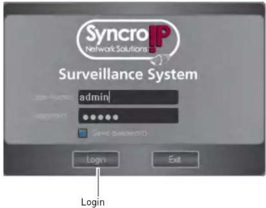
NOTE: The CMS default User Name is admin and the Password is admin.
Adding a NVR from the Local Area Network (LAN)
Once you open the software, you can add a NVR.
Prerequisites:
- Connect the NVR to a router or switch on the network.
• Install the CMS on a computer in the same LAN as the NVR.
To add a NVR:
- Click Config Manager→Device Manage.

- Click Search Device. If a Windows Firewall alert appears, click Allow.
- Check the NVR and click Add Management.
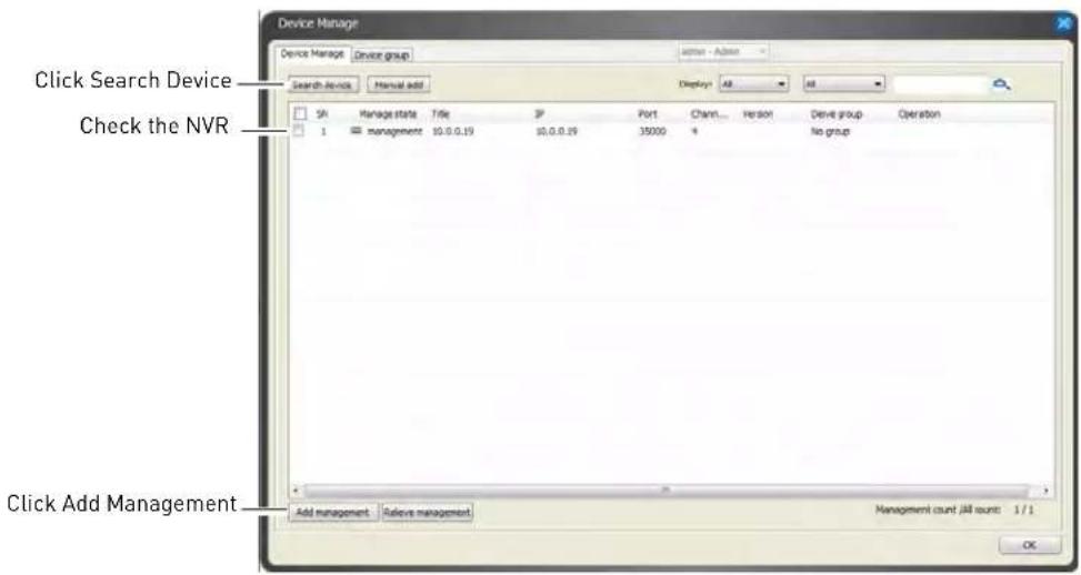
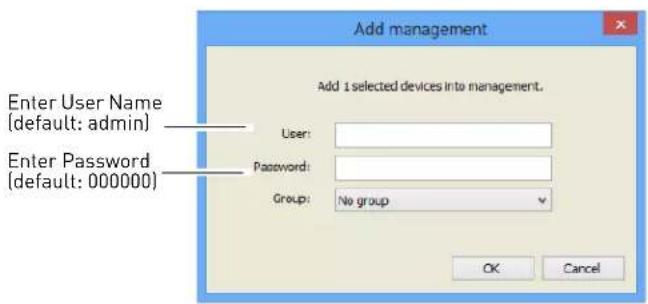
- Enter the User Name (default: admin) and Password (default: 000000) for the NVR and click OK.
- Click OK.
-
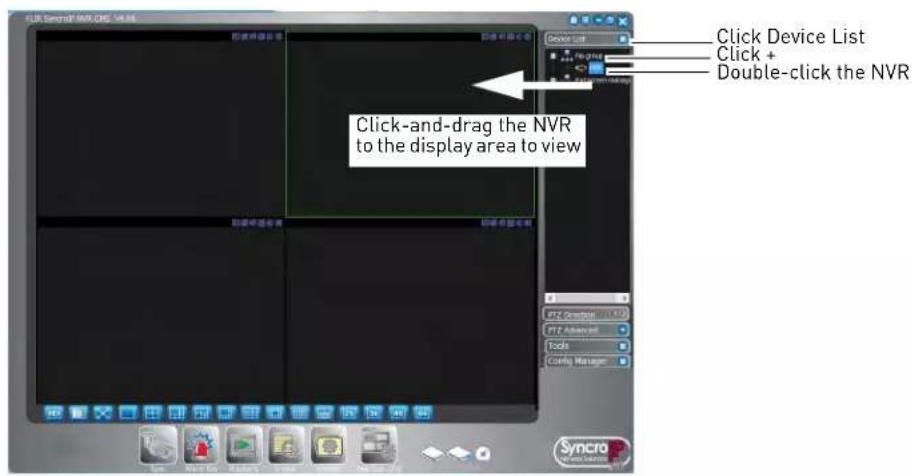
Click Device List.
-
Click + next to No Group.
- Double-click the NVR.
- Click-and-drag the NVR to the display area to view.
Adding a NVR using a DDNS address
If you have NVR systems with DDNS set up, you can add them to the CMS.
Prerequisites:
- Create a DDNS account. For details, see "Appendix D: Setting Up DDNS Service" on page 97.
- Enter the DDNS information into the NVR locally.
- Port forward the Client and HTTP ports (default, ports 80 and 35000) on the router.
To add a NVR using a DDNS address:
- Click Config Manager→Device Manage.

2. Click Manual Add.

3. Configure the following:
- Title: Enter a name for your NVR of your choice (e.g. home or office).
- Type: Select NVR.
- Add Type: Select Domain Name.
- Domain Name: Enter the Domain Name from the confirmation email after your registered for DDNS, followed by .digimerge.net.
- Port: Enter the Client Port (default: 35000).
- User: Enter the NVR's user name (default: admin).
- Password: Enter the NVR's password (default: 000000).

- Click Ad d, then click OK.
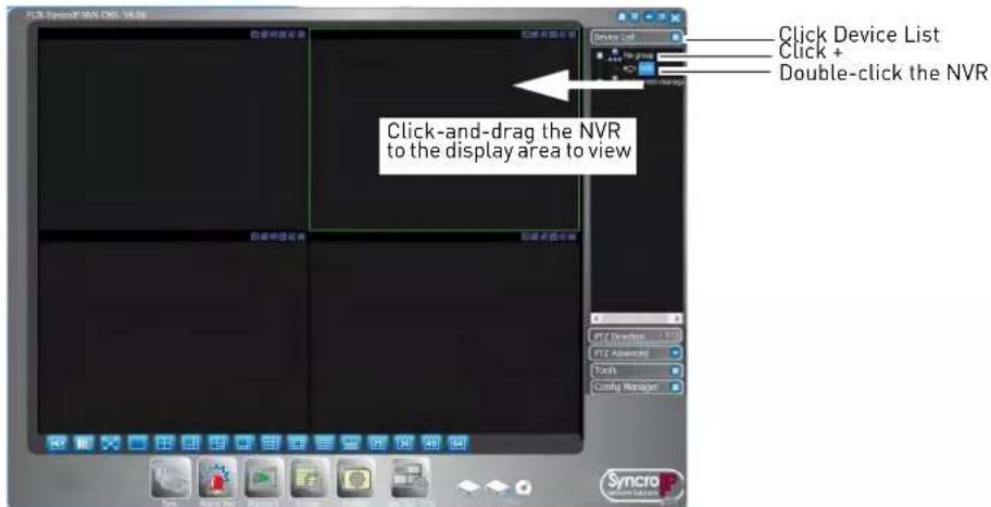
- Click Device List.
- Click + next to No Group.
-
Double-click the NVR.
-
Click-and-drag the NVR to the display area to view.
CMS Live Viewing Overview
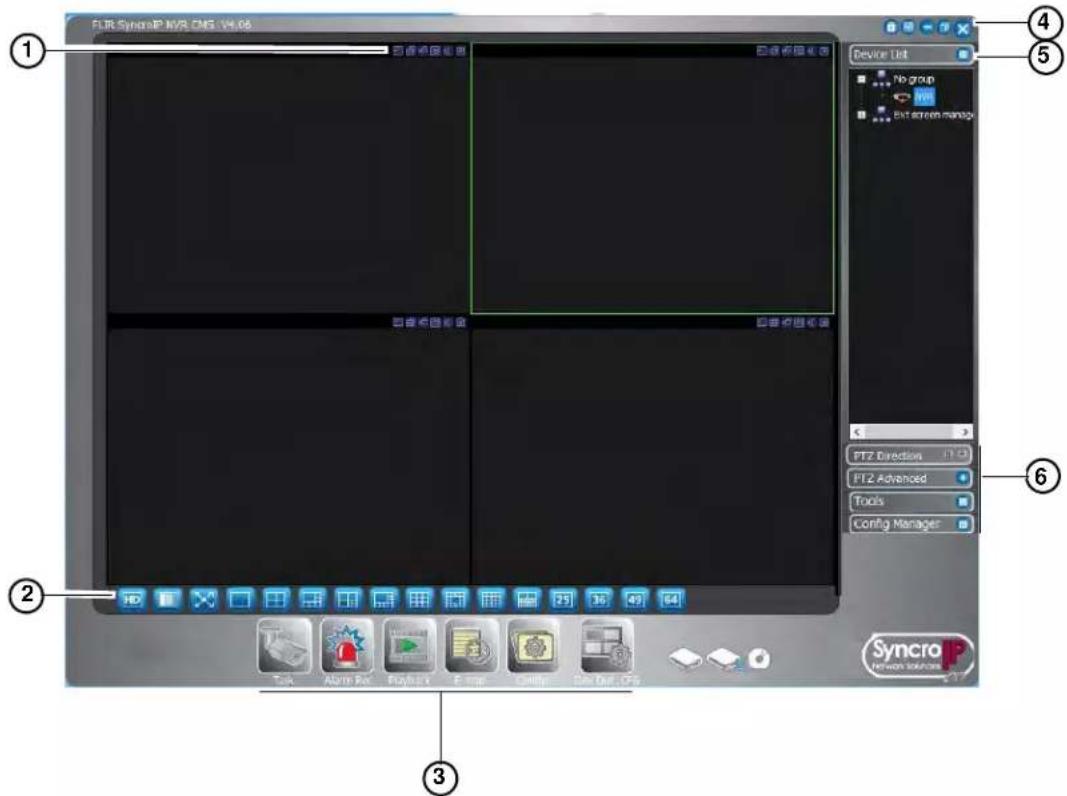
- Camera Controls:

2. Live View Toolbar:

-
CMS Quick Menus: Click to access key CMS and NVR functions, such as Playback, event search (Alarm Rec), E-Map, and software configuration (Config).
-
CMS Window Contr ols:
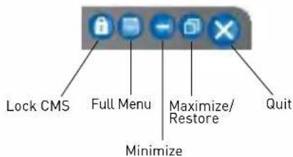
-
Device List: Open NVR's and IP cameras in live display.
-
Click + next to NVR's or Groups to expand.
- Click and drag NVR's, Groups, or Cameras to the display area to open.
-
Right-click NVR's, Groups, or Cameras to view system options.
-
CMS Menus:
-
PTZ Direction: Access basic PTZ controls.
- PTZ Advanced: Access advanced PTZ controls (e.g. Auto Scan, Tour, etc.).
- Tools: Contains the following menus: Begin Record Plan, NVD Control, Health Report, Log Search, Alarm Video, Alarm Output, Color Config, Volume.
- Config Manager: Contains the following menus: Scheme Task Config, Record Plan Config, Alarm Config, Alarm Rec Config, E-Map Config, DecCard Config, User Manage, Device Manage, Ext Screen Manage, User Config.

Using Alarm Rec (Event Search)
Alarm Rec allows you to search for events saved on the NVR.
To use Alarm Rec:
- Click Alarm R ec (
- At the top of the screen, select the alarm type you would like to search.

3. Check Search.

- Under Device, select the NVR you would like to search.
- Under Start Time and End Time, enter the start and end times for your search.
- Click Search. A list of relevant alarms appears below.
Using Playback Mode
You can view recorded footage from your NVR's in the CMS software.
To use playback mode:
- Click Playback (

- Under Device, select the NVR and channel you would like to search.

- Check Multiple channel to playback video from multiple cameras. Select camera and then click Add. Repeat to add additional cameras.
- Under Parameter, select the start and end time for the search.
-
Click Search.
-
Check video files to select and click Play to open.
OR, click Download to download the video files to the local computer.
OR, click To AVI to convert the video files to AVI and save to your local computer.
NOTE: You must stop playback before you may download video files.
Playback Controls
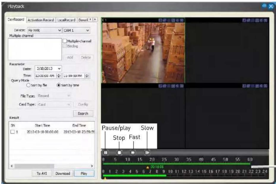
Click and drag to select playback time. Use the top bar to select minutes and the bottom to select hours
Configuring Monitoring Tasks and Projects
Tasks are used to configure the CMS to automatically cycle through different channel arrangements. Projects are used to automatically cycle through multiple tasks.
Configuring Tasks
- Click Config Manager→Scheme Task Config.
2. Click Monitor Task.

- Click New.
- Enter a Task Name of your choice.
- Under Window, select the split-screen mode you would like to show in the task.
-
Under Monito r Item, configure the following:
-
Window: Select the display window you would like to configure.
- Device: Click and drag the camera from the Device List in the main CMS window to the field to add it.
- Stream Type: Select Main Stream or Extra Stream to view the sub-stream.

- Click Ad d. Repeat Steps 6 & 7 to configure additional screens.
- Click OK. Click OK to save changes.
Configuring Projects
Once you have multiple tasks set up, you can configure projects to automatically cycle through them.
To configure a project:
- Click Config Manager→Scheme Task Config.
- Click Monitor Project.
Click Monitor Project
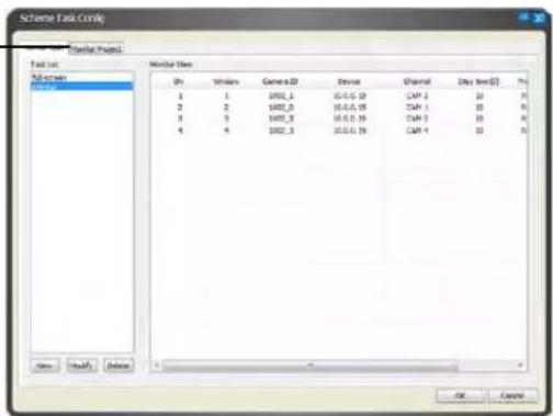
- Click New.
- Enter a Name for the project. You may not change the name after the project is created.
- Under Mode, select Tour Mode or Schedule Mode. Tour Mode will cycle through tasks on a fixed interval. Schedule Mode will switch tasks at a pre-defined time of the day.

-
Under Task Name, select the task you would like to add to the project.
-
If you selected Tour Mode, enter the Interval Time in minutes that the task will run for before changing to the next task.
-
If you selected Schedule Mode, enter the time of day when the task will start running.
-
Click Add.
-
Repeat steps 6-7 for each additional task you would like to add to the project.
- Click OK. Click OK to save changes.
Running Tasks and Projects
- Once you have configured tasks or projects, you may run them by clicking Task ( ) and then selecting the task or project you would like to run.
- You may also select a task or project to run when you first launch the CMS. For details, see "Configuring CMS Options" on page 52.
Using E-Map
The E-Map feature allows you to visually map your cameras over a .jpg image.
Configuring E-Map
Use the steps below to select a .jpg image to use for the E-Map and place your cameras.
To configure the E-Map:
-
Click Config Manager→E-Map Config.
-
Cl ick Picture Edit.
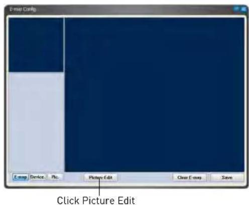
- Click Add.
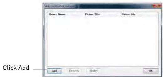
-
Click Browse. Select a .jpg image on your computer to use as the E-Map.
-
Enter a Name and Title for your E-Map of your choice.
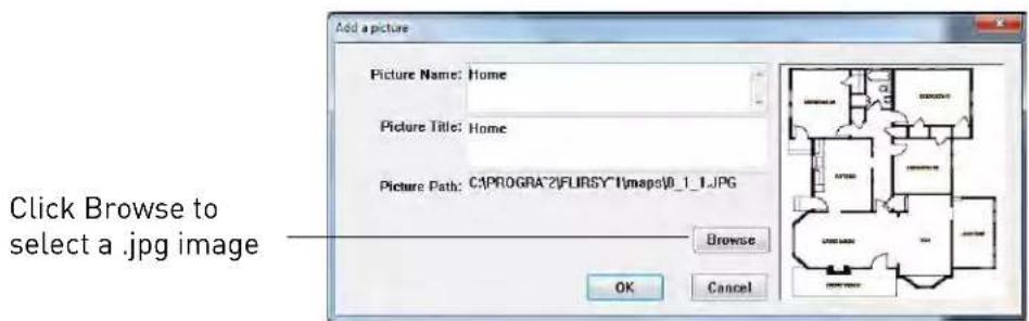
-
Click OK.
-
Click Pic.
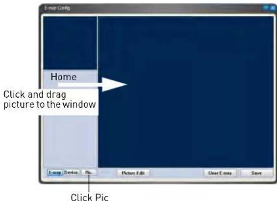
-
Click-and-drag the picture to the window to use it for the E-Map.
-
Click Device to view a list of connected NVR's.
-
Click + next to an NVR. To place cameras, drag cameras from the list to the map.

- Click Save.
NOTE: To delete all E-Map data, including images and camera positions, click Clear E-Map.
Opening Cameras from E-Map
Once you have configured your E-Map, you can use it to open cameras in live display.
To open cameras from E-Map:
- Click E-Map ( ).

- Click on a display area in the main CMS window, then double-click on the camera to open it.
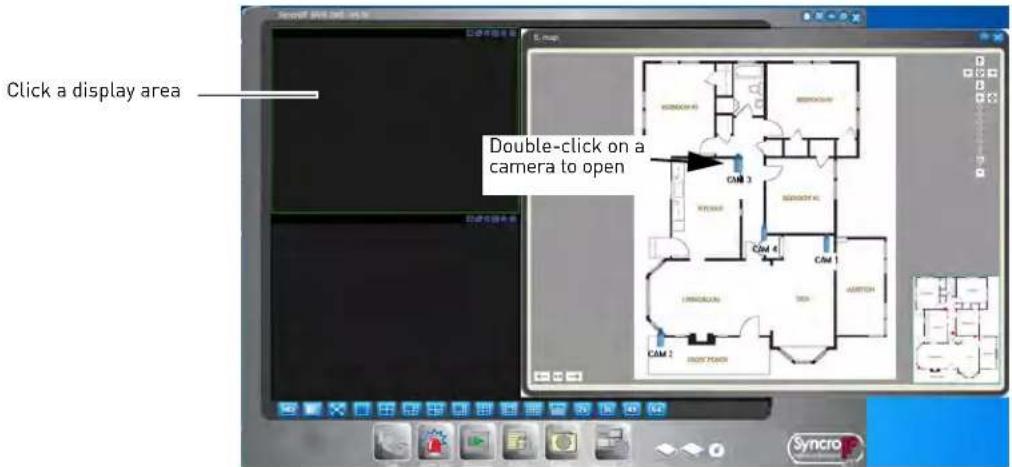
Configuring the CMS
You can configure settings for the CMS such as the admin password, recording directories, and start up settings through the Config menu.
Configuring CMS Options
- Click Config()→Options.
- Configure the following:


- Verify password: Check to require passwords when logging into or closing the CMS.
- Log in all devices: Check to allow the CMS to log into all NVR's when it opens.
-
Auto start record plan: Check to have the CMS automatically start the record plan, which allows recording to the computer hard drive when it opens. To configure the record plan, click Config Manager→Record Plan Config.
-
Auto Login : Check for the CMS to automatically log in the admin account when it is opened.
- Hotkey Setup: Configure hotkeys for the CMS. Use the drop-down menu to select the command, and then click inside the box on the right and enter the hotkey.
NOTE: Do not use F12 as a hotkey. F12 is reserved for the system debug command.
- Displayed items in the right bar: Select which right-side menu is opened when the CMS opens.
- Record Time (M): Select the length in minutes of video files recorded on your computer hard drive. For example, if you select 15 minutes, the system will save a new video file for every 15 minutes of recording.
- Snapshot picture path: Click ... to select the default save folder for snapshots.
- Picture file name rule: Click ... to define the file name rule for snapshots.
- Recorded file path: Click ... to select the default save folder for manual recordings.
- Recorded file name rule: Click ... to select the file name rule for manual recordings.
- Downloaded file path: Click ... to select the folder for downloaded recording files.
- Download record file name rule: Click ... to define the file name rule for downloaded recording files.
- Device free minimum space (MB): Enter the amount of minimum space in MB to maintain on the computer hard drive. The system will stop recording when only this much space is left.
- Auto Start Project: Check for the CMS to automatically run a project when opened. Select the project it will run under Project Name.
- Auto Start Task: Check for the CMS to automatically run a task when opened. Select the task it will run under Task Name.
- Last Run: Check for the CMS to start the last used task or project when opened.
- Save last monitor status: Check to have the CMS restore the previously used display mode when opened.
- Auto sync PC time to device: Check to have the NVR sync the clock with the system time on the PC.
- Sync time becomes valid at: Select the time that the NVR will sync its clock with the PC's system time.
- Week: Select days that the NVR will sync its clock with the PC's system time.
-
Auto reboot device: Check to enable the NVR to reboot when the time sync occurs.
-
Click 0k t o save changes. Close the CMS and restart it to update the configuration.
Changing the CMS Admin Password
You can change the admin password that is used to log into the CMS. The default password is admin.
NOTE: The CMS will automatically populate the admin password unless you enable Verify Password under Config→Options.
To change the CMS admin password:

- When logged in as the admin account, click Config( )→Modify Password.
- Under Old Password, enter the old password.
- Under New Password and Confirm Password, enter the new password.
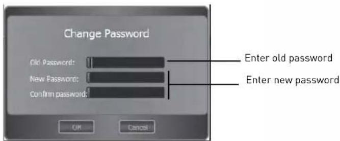
- Click OK.
Adding User Accounts to the CMS
You can add multiple user accounts to the CMS with varying levels of access to the system.
NOTE: To make sure users must enter their user name and password to access the CMS, you must make sure Verify User is checked and Auto Login is unchecked in Config→Options. For details, see "Configuring CMS Options" on page 52.
To add a user account to the CMS:
- Click Config Manager→User Manage.
- Cl ick Add.

-
Configure the following:
-
User: Enter the user name for the account.
- Password/Confirm: Enter the password for the account.
-
Name/Sex/Information: (Optional) Enter descriptive details about the user account.
• Right: Check the permissions that will apply to the user account. -
Click Sav e. Click OK to save changes.
Multi-Monitor Support
The CMS supports up to 4 monitors on a single system. The recommended system specifications is listed below. If your system does not meet the requirements below, you may experience slow system performance.
Minimum system recommendations to run the CMS on multiple monitors:
- Intel Core i5 or i7 processor.
- 6 GB of RAM.
- Geforce 9500GT video card, 1GB or greater.
Opening Cameras in Secondary Monitors
- To open a single channel on a secondary monitor: Open it in a window on the main screen, then right-click on the display area, and select Output current window to extension screen. Select the monitor you would like to send the channel to.
- To open multiple-channels on a secondary monitor: Open your desired channel view, then right click in the display area, and select Output all windows to extension screen. Select the monitor you would like to send them to.
![[Pir NIVS] © Kaps S Talk Audio Format Output current window to the extension screen Output all windows to the extension screen Copy Video Info Close current window video Close Videos of all windows Video Attribute Right-click and select output option to open channels on a secondary monitor](/content/2026/05/1002354/images/d44890d9fd98f5cf02673c9a4f96f0c755ed87cd198f58504a6cdc978e956649.jpg)
Managing Secondary Monitors
Use Ext Monitor Config to configure settings for secondary monitors. You can select which monitors you would like to enable. Enabled monitors start up when you open the CMS software.
You can close secondary monitors by clicking on them and then pressing ESC. However, you must close the CMS software and restart it to re-open windows on secondary monitors.
To manage secondary monitors:
-
Click Config Manager→Ext Scr een Manager.
-
Click Search to detect secondary monitors or Identify to display the monitor number assigned to each secondary monitor.

- Check monitors to open them when the CMS software opens or uncheck to disable.
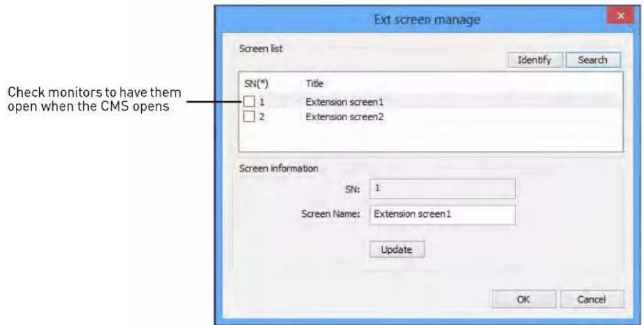
- Click OK to save changes. Restart the CMS software to open the new monitor configuration.
REMOTE VIEWING ON INTERNET EXPLORER
You can also view your system remotely using Internet Explorer (version 8 or later required).
NOTE: Remote viewing is only compatible with Internet Explor and other browsers are not supported.
er. Mozilla Firefox, Opera, Safari,
Prerequisites
- The HTTP Port (default: 80) and Client Port (default: 35000) must be port forwarded to your router.
- You must create a DDNS account, and have the DDNS settings configured in your NVR. For details, see "Appendix D: Setting Up DDNS Service" on page 97.
- The NVR must have internet access.
To view your system using Internet Explorer:
- Open Internet Explorer. Note that it is recommended to select Run as Administrator when opening Internet Explorer to ensure full functionality.
-
In the address bar, enter your system's IP address or DDNS address followed by the HTTP Port (default: 80). For example, http://192.168.1.1:80 or http://tomsmith.digimerge.net:80
NOTE: You MUST include http:// in order to access your system. -
An attention bar appears at the top or bottom of the screen t o prompt you to install ActiveX plugins, click Install or Allow and follow the prompts to install the plugins.
-
Enter the system user name and password (by default admin / 000000).
-
Select LAN to connect using the main (high quality) stream. Select WAN to use the sub-stream to conserve bandwidth and for improved performance when connecting over the Internet.
-
Click Login to log in.

- Click and drag cameras to the display window to view them live.

NOTE: Some options are not available in WAN mode.

- Cameras: Click and drag to the display area to view.
- Live View Contr ols:
- Open All: Click to open all cameras.
- Local Play: Open recorded or back up video files (.dav) saved on the local computer.
- Refresh: Click this button to refresh monitor channel name.
3. Camera Controls:

NOTE: Manual Recordings are saved to C:|RecordDownload. Snapshots are saved to C:|PictureDownload. You must select Run as Administrator when you open Internet Explorer to use these functions.
4. Live Vie w Toolbar:

5. PTZ Controls
- Color Settings: Use the sliders to adjust the brightness, contrast, saturation, and hue for the selected camera.
Using Search Mode in IE (Playback)
You can access recorded video from your NVR using the Internet Explorer client.
To access recorded video from your NVR:
- Cl ick Search.
-
Co nfigure the following search options:
-
Type: Select the type of recording to search for.
- Begin Time/End Time: Select the start and end for your search.
- Channel: Select the channel you would like to search or select All.
- Main Stream: Check to search for main stream recordings.
-
Extra Stream: Check to search for Extra Stream recordings. Extra Stream recordings are lower recording that may be saved on the system to reduce the bandwidth required for remote playback.
-
Click Sear ch.
-
Under Multiple-channel Playback, select the channels you would like to playback.
-
Click a search result and then click Playback to open or Download to save the file to your computer hard drive.
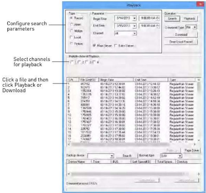
Playback Controls
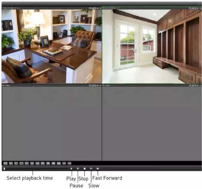
MOBILE CONNECTIVITY
The DNR200 Series is compatible with iPhone, iPad and Android devices.
iPhone
DigiNet NVR is an iPhone app that allows you to remotely view your NVR.
System Requirements
- iOS 4.3 or later.
Prerequisites
- Port 80 and 35000 (or your HTTP and Client Ports, if you have changed them) must be port forwarded to your router.
- You must create a DDNS account, and have the DDNS settings configured in your NVR.
- The NVR must have internet access.
- You must have a DDNS address to log in remotely.
- An iTunes account.
NOTE: You will need to create an iTunes account before you can download the app. An iTunes store account requires a valid credit card number. The app is free of charge.
Connecting to your NVR on an iPhone
- Download DigiNet NVR for free from the App Store.
- Tap on the DigiNet NVR icon ( ) to start the app.
- Tap
- Tap Device Manager.

Device Manager
5. Tap Add→Manually Add.

6. Configure the following:
- Name: Enter a name for your NVR of your choice.
- Address: Enter your DDNS address (e.g. tomsmith.digimerge.net).
- Port: Enter the Client Port (default: 35000).
- Username: Enter the NVR's User Name (default: admin).
- Password: Enter the NVR's Password (default: 000000).
- Channel: Enter the number of channels your NVR has.

7. Tap Save.
8. Tap
9. Tap Live Preview.
- Tap + on one of the display areas and select the camera you would like to open in the selected display area.
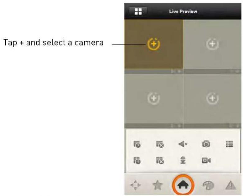
- Repeat to view additional cameras.
DigiNet NVR Interface
You can use DigiNet NVR in portrait and landscape mode.
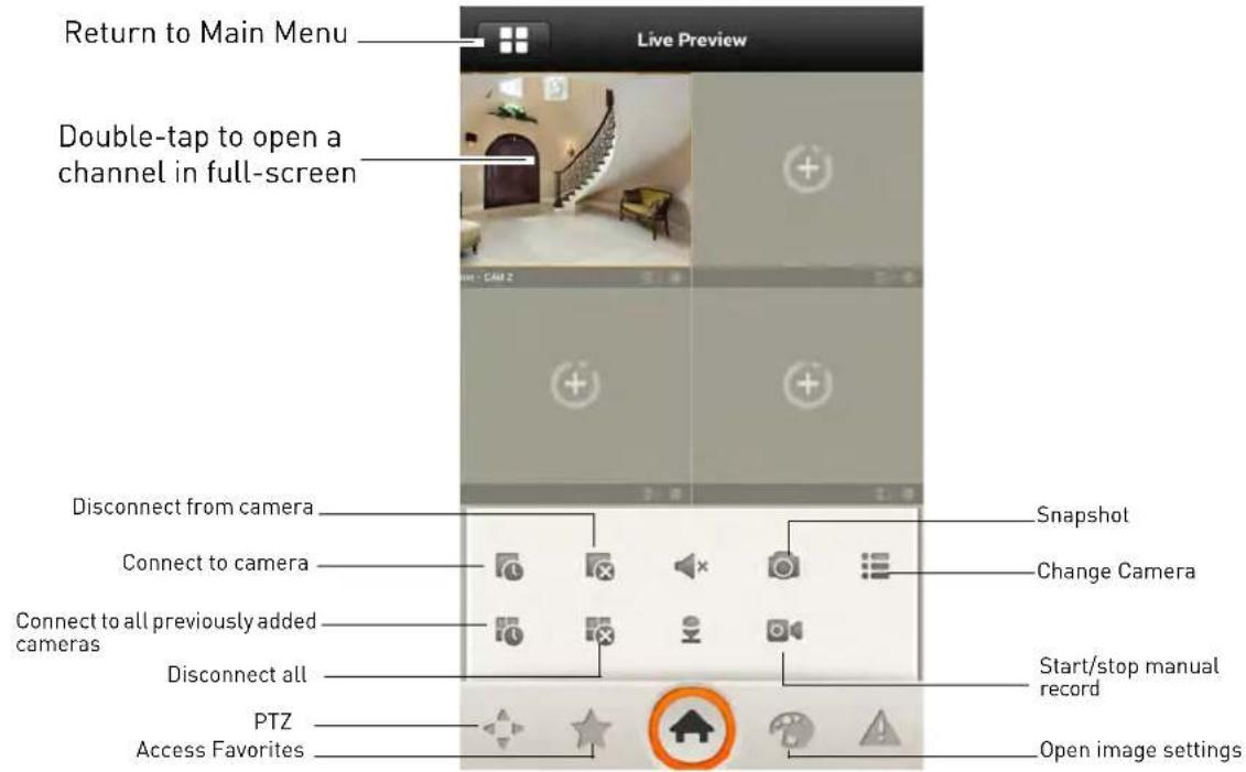
Viewing Videos with Local File
If you have saved videos using DigiNet NVR, you may open them with Local File.
NOTE: You may open screenshots using the Photos app.
To access Local File:
• From the Main Menu, tap Local File.
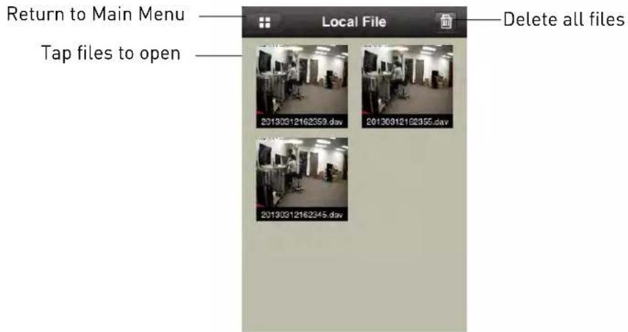
Using Playback Mode on iPhone
You can access recorded video on your NVR using your iPhone.
NOTE: You must enable Extra Stream Recording to use playback mode on mobile devices. For details on enabling Extra Stream Recording, see "Recording" on page 24.
To use Playback Mode:
- From the Main Menu, tap Playback.
NOTE: If Playback is not shown, tap Add, check Playback, and return to the Main Menu.
- Tap +.

-
Select the start and end times to playback.
-
Select a channel to playback.
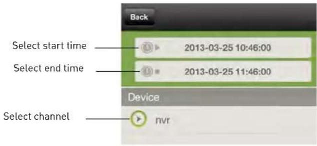
- Use the on-screen controls to control playback.
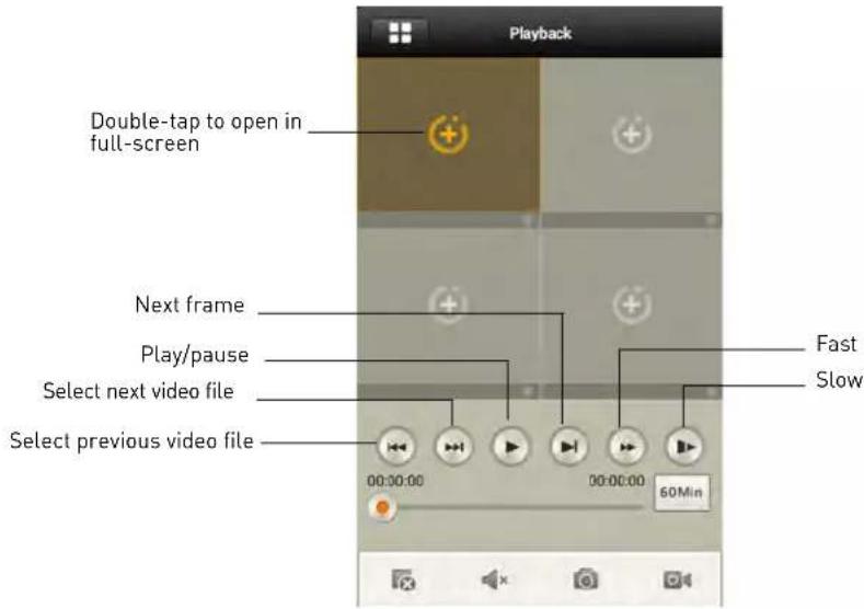
Enabling Push Notifications
You can have the app send push notifications to the notifications area on your device when one of your cameras detects motion. Once you have received a push notification, you can select it to open live video from the camera that detected motion.
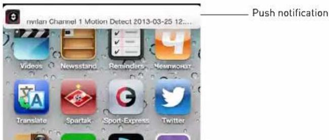
NOTE: Your cameras must have motion detection activated to receive push notifications. For details on enabling motion detection, see "Motion" on page 28.
To enable Push Notifications:
- From the Main menu, tap Push Config.
NOTE: If Push Config is not shown, tap Add, check Push Config, and then return to the Main Menu.
- For the NVR you would like to configure, set the slider to ON.

- Tap Motion Detect and then check each channel you would like to receive push notifications from.

- Tap OK. A test notification will be sent to your device. After this, whenever the selected cameras detect motion, you will receive a notification.
NOTE: You can see a list of notifications through the Event List menu. To show the Event List menu, tap Add and check Event List. Return to the Main Menu and select Event List. Tap on events to view live video from the camera.

Device Manager
You can use Device List to manage your NVR's.
To access Device List:
• From the Main Menu, tap Device Manager.
To edit an NVR:
- Tap the NVR in Device Manager.
-
Edit the connection details as needed.
-
Tap Save.
To delete an NVR:
- Swipe right on the NVR you would like to delete.

Swipe right on the NVR you would like to delete and tap delete
- Tap Delete. Tap OK to confirm.
iPad
DigiNet NVR HD is an iPad app that allows you to remotely view your NVR.
System Requirements
- iOS 4.3 or later.
Prerequisites
- Port 80 and 35000 (or your HTTP and Client Ports, if you have changed them) must be port forwarded on your router to your NVR's IP address.
- You must create a DDNS account, and have the DDNS settings configured in your NVR.
- The NVR must have internet access.
- You must have a DDNS address to log in remotely.
NOTE: You will need to create an iTunes account before you can download the app. An iTunes store account requires a valid credit card number. The app is free of charge.
Connecting to your NVR on an iPad
-
Install DigiNet NVR HD for free from the App Store.
-
Tap on the DigiNet NVR HD icon ( ) to start the app.
-
Tap

then

- Tap Device Manager.
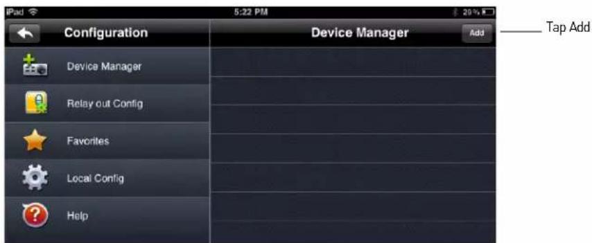
- Tap Add.
6. Configure the following:

- Name: Enter a name for your NVR of your choice.
- Address: Enter your DDNS address (e.g. tomsmith.digimerge.net).
- Port: Enter the Client Port (default: 35000).
- Username: Enter the NVR's User Name (default: admin).
- Password: Enter the NVR's Password (default: 000000).
- Channel amount: Enter the number of channels your NVR has.
7. Tap Sav e.
8. Tap
- In landscape mode: tap a channel and then select the camera you would like to view on the left.
OR
In portrait mode: tap + on one of the display areas and select the camera you would like to open.

DigiNet NVR HDInterface
You can use DigiNet NVR HD in landscape or portrait mode.

Device Manager
Device Manager allows you to manage your NVR's.
To access Device Manager:
- From live view, tap

then

- Tap Device Manager.
To delete an NVR:
- Tap the NVR to select it.
- Tap ☐. Tap Yes to confirm.

To modify an NVR:
- Tap an NVR to select.
- Tap the NVR again to open the edit screen.
- Update the connection details as needed and then tap Sav e.
Using Playback Mode on iPad
You can access recorded video on your NVR using your iPad.
NOTE: You must enable Extra Stream Recording to use playback mode on mobile devices. For details on enabling Extra Stream Recording, see "Recording" on page 24.
To use Playback Mode:
- From Live View tap

then

- In Portrait Mode: Tap +, select the start time and end time for your search, and select the camera you would like to playback.
OR
In Landscape Mode: Select the start time and end time for your search, and select the camera you would like to playback.

- Use the playback controls.

NOTE: Playback controls are only shown in portrait mode.
Enabling Push Notifications
You can have the app send push notifications to the notifications area on your device when one of your cameras detects motion. Once you have received a push notification, you can select it to open live video from the camera that detected motion.

NOTE: Your cameras must have motion detection activated to receive push notifications. For details on enabling motion detection, see "Motion" on page 28.
To enable Push Notifications:
- From live view, tap

then

-
Tap Alarm Push.
-
Set the slider to ON next to the NVR you would like to configure.

- Tap Motion Detect then check each channel you would like to receive push notifications from.

- Tap OK. A test notification will be sent to your device. After this, whenever the selected cameras detect motion, you will receive a notification.
NOTE: You can see a list of notifications through the Event List menu. To show the Event List
menu, from live view, tap then

Tap on an event to view live video from the camera

Android Phones
DigiNet NVR allows you to remotely view your NVR on Android smartphones.
A separate app is available to remotely view your NVR on Android tablets, to make better use of the larger screen size. For details, see "Android Tablets" on page 78.
Compatible Devices
- Android OS [2.2 and above].
Prerequisites
- Port 80 and 35000 (or your HTTP and Client Ports, if you have changed them) must be port forwarded on your router to your NVR's IP address.
- You must create a DDNS account, and have the DDNS settings configured in your NVR.
• The NVR must have internet access. - You must have a DDNS address to log in remotely.
Connecting to your NVR on an Android Phone
- Download DigiNet NVR for free from the Google Play Store.
- Tap on the DigiNet NVR icon ( ) to start the app.
- Tap
4. Tap Device Manager.

5. Tap Add→Manually Add.

6. Configure the following:
- Name: Enter a name for your NVR of your choice.
- Address: Enter your DDNS address (e.g. tomsmith.digimerge.net).
- Port: Enter the Client Port (default: 35000).
- Username: Enter the NVR's User Name (default: admin).
- Password: Enter the NVR's Password (default: 000000).
- Channel: Enter the number of channels your NVR has.
7. Tap Sav e.
- Tap
- Tap Live Preview.

- Tap + on one of the display areas and select the camera you would like to open in selected display area.

- Repeat to view additional cameras.
DigiNet NVR Interface
You can use DigiNet NVR in portrait and landscape mode.
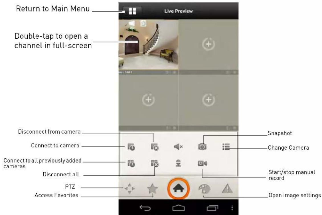
Viewing Snapshots and Videos with Local Files
If you have saved snapshots or videos using DigiNet NVR, you may open them with Local Files.
To access Local Files:
- From the Main Menu, tap Local Files.
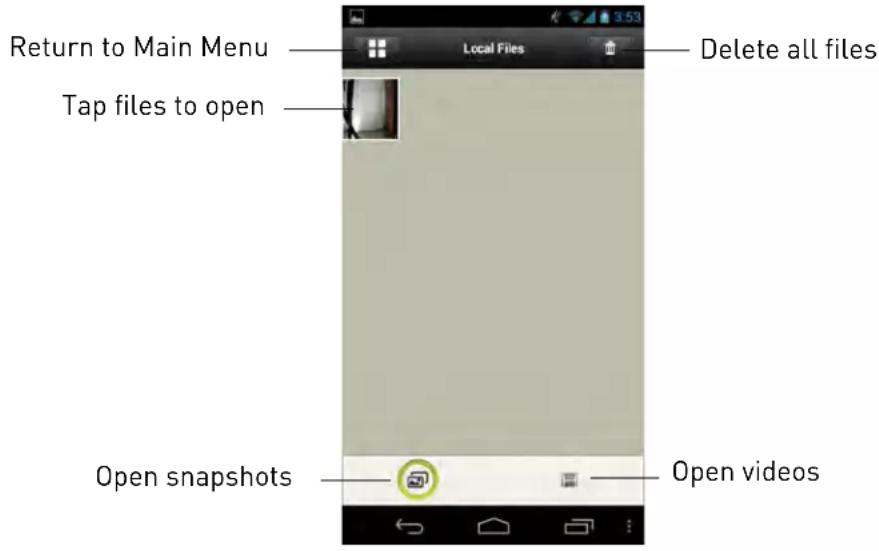
Using Playback Mode on Android Phones
You can access recorded video on your NVR using your Android phone.
NOTE: You must enable Extra Stream Recording to use playback mode on mobile devices. For details on enabling Extra Stream Recording, see "Recording" on page 24.
To use Playback Mode:
- From the Main Menu, tap Playback.
-
If Playback is not shown, tap Add, check Playback, and return to the Main Menu.
-
Tap + and select a channel to playback.

- Select the date then the start and end times to playback.
- Use the on-screen controls to control playback.

Enabling Push Notifications
You can have the app send push notifications to the notifications area on your device when one of your cameras detects motion. Once you have received a push notification, you can select it to open
live video from the camera that detected motion.

NOTE: Your cameras must have motion detection activated to receive push notifications. For details on enabling motion detection, see "Motion" on page 28.
To enable Push Notifications:
- From the Main menu, tap Push Config.
NOTE: If Push Config is not shown, tap Add, check Push Config, and then return to the Main Menu.
- Tap the NVR you would like to configure.

- Tap Motion Detect and then check each channel you would like to receive push notifications from.
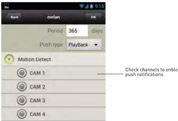
- Tap OK. A test notification will be sent to your device. After this, whenever the selected cameras detect motion, you will receive a notification.
NOTE: You can see a list of notifications through the Event List menu. To show the Event List menu, tap Add and check Event List. Return to the Main Menu and select Event List. Tap on events to view live video from the camera.

Device Manager
You can use Device List to manage your NVR's.
To access Device List:
• From the Main Menu, tap Device Manager.
To edit an NVR:
- Tap the NVR in Device Manager.
-
Edit the connection details as needed.
-
Tap Save.
To delete an NVR:
- Swipe the NVR you would like to delete to the right.
- Tap Del ete. Tap OK to confirm.
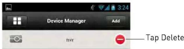
Android Tablets
DigiNet NVR HD is an app that allows you to remotely view your NVR on an Android tablet.
System Requirements
- Android 3.3 or later.
Prerequisites
- Port 80 and 35000 (or your HTTP and Client Ports, if you have changed them) must be port forwarded on your router to your NVR's IP address.
- You must create a DDNS account, and have the DDNS settings configured in your NVR.
- The NVR must have internet access.
- You must have a DDNS address to log in remotely.
Connecting to your NVR on an Android Tablet
-
Install DigiNet NVR HD for free from the Google Play Store.
-
Tap on the DigiNet NVR HD icon ( ) to start the app.
-
Tap

then

- Tap Device Manager.
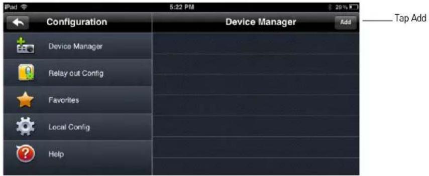
-
Tap Add.
-
Configure the following:

- Name: Enter a name for your NVR of your choice.
- Address: Enter your DDNS address (e.g. tomsmith.digimerge.net).
- Port: Enter the Client Port (default: 35000).
- Username: Enter the NVR's User Name (default: admin).
- Password: Enter the NVR's Password (default: 000000).
-
Channel amount: Enter the number of channels your NVR has.
-
Tap Save.
-
Tap

- In landscape mode, tap a channel and then select the camera you would like to view on the left. In portrait mode, tap + on one of the display areas and select the camera you would like to open.

DigiNet NVR HD Interface
You can use DigiNet NVR HD in landscape or portrait mode.

Using Playback Mode on Android Tablets
You can access recorded video on your NVR using your Android tablet.
NOTE: You must enable Extra Stream Recording to use playback mode on mobile devices. For details on enabling Extra Stream Recording, see "Recording" on page 24.
To use Playback Mode:
- From Live View tap

then

- In Portrait Mode: Tap +, select the start time and end time for your search, and select the camera you would like to playback.
OR
In Landscape Mode: Select the start time and end time for your search, and select the camera you would like to playback.
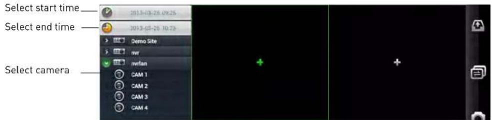
- Use the playback controls.
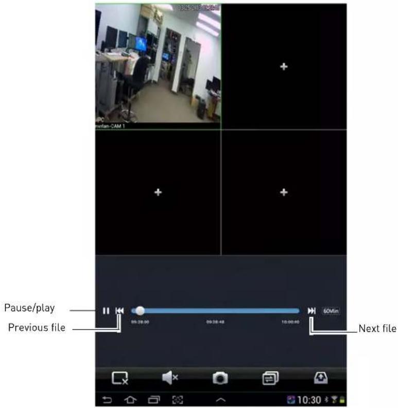
NOTE: Playback controls are only shown in portrait mode.
Enabling Push Notifications
You can have the app send push notifications to the notifications area on your device when one of your cameras detects motion. Once you have received a push notification, you can select it to open live video from the camera that detected motion.

NOTE: Your cameras must have motion detection activated to receive push notifications. For details on enabling motion detection, see "Motion" on page 28.
To enable Push Notifications:
- From live view, tap

then

- Tap Alarm Push.
- Select the NVR you would like to configure.
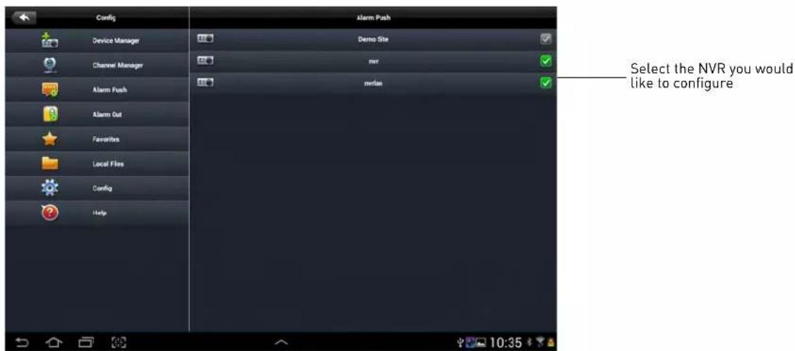
- Tap MotionDetect then check each channel you would like to receive push notifications from.
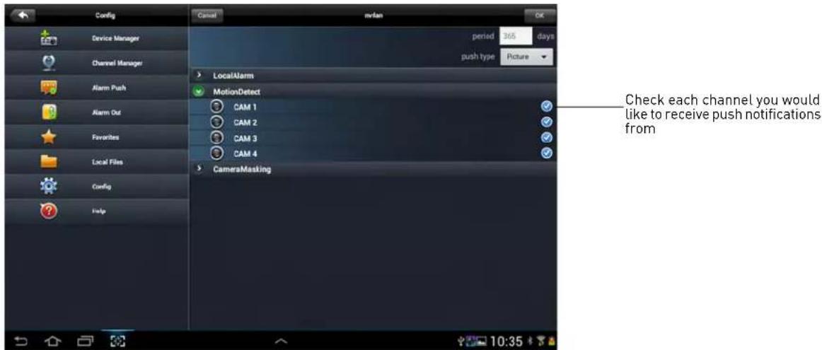
- Tap OK. A test notification will be sent to your device. After this, whenever the selected cameras detect motion, you will receive a notification.
NOTE: You can see a list of notifications through the Event List menu. To show the Event List
menu, from live view, tap 📋 then


Tap on an event to view live video from the camera

Device Manager
Device Manager allows you to manage your NVR's.
To access Device Manager:
- From live view, tap

then

- Tap Device Manager.
To delete an NVR:
-
Tap the NVR to select it.
-
Tap . Tap OK to confirm.

To modify an NVR:
- Tap an NVR to select.
- Tap the NVR again to open the edit screen.
- Update the connection details as needed and then t ap Save.
APPENDIX A: SYSTEM SPECIFICATIONS
System
Main Processor Dual-core embedded processor
Operating System Embedded LINUX
Pentaplex Operation Simultaneous View, Record, Playback, Backup, and Remote Monitoring
Inputs/Outputs
IP Camera Input 4 channel
Power over Ethernet (PoE) 4 integrated PoE ports
Audio 1 channel input (RCA), 1 channel output (RCA)
PTZ RS-485, supports Pelco-D and Pelco-P
USB 3 ports
Alarm Input 3 Channel
Relay Out 3 Channel
Display
Interface 1 HDMI, 1 VGA
Resolution 1920×1080, 1280×1024, 1280×720, 1024×768
Display Split 1/4
OSD Camera Title, Time, Camera Lock, Motion Detection, Recording Status
Recording
Compression H.264
Resolution 1080P (1920×1080) / VGA (640×480)
Record Rate 120fps@1080P
Bit Rate 32Mbps
Record Mode High Quality Stream/Sub-Stream Recording: Manual, Schedule, Motion Detection, Alarm
Record Interval 1\~120 min (default: 60 min), Pre-record: 1\~30 sec, Post-record: 10\~300 sec
Video Detection and Alarm
| Trigger Events | Recording, PTZ, Tour, Alarm, Video Push, Email, FTP, Buzzer & Screen tips |
| Video Detection Motion Detection | |
Playback and Backup
| Sync Playback 1/4 |
| Playback Function 4 Channel |
| Backup Mode USB Device / Network |
| Configuration Backup To USB Device |
Network
| Ethernet RJ-45 port (10M/100M/1000M) | |
| Network Function | HTTP, TCP/IP, IPv4/IPv6, UPNP, RTSP, UDP, SMTP, NTP, DHCP, DNS, IP Filter, PPPOE, DDNS, FTP, Alarm Server, IP Search |
| Max. User Access 20 simultaneous users | |
| Smart Phone iPhone, iPad, Android | |
| IP Cameras Supported | FLIR, Digimerge, Panasonic, Sony, Dynacolor, Samsung, AXIS, Arecont |
Storage
| SATA Ports | 2 internal SATA ports (2HDD) + external eSATA (4HDD) |
| Maximum Storage Capacity | 6TB (2 x 3TB) internal + 12TB (4 x 3TB) external using eSATA |
Dimensions
| Weight 2.3kg / 5.1lbs | |
| Package Dimensions | 100mm x 220mm x 146mm / 3.9" x 8.7" x 5.7" (W x H x D) |
Power
| Power Supply 1x 12V DC 5A (for NVR); 1x 48V DC 1A (for PoE) |
As our products are subject to continuous improvement, Digimerge Technologies Inc., a FLIR company, and its subsidiaries reserve the right to modify product design, specifications, and prices without notice and without incurring any obligation. E&OE
APPENDIX B: SETTING UP REMOTE VIEWING
Setting up the Remote Viewing Feature requires several steps. Networking skills are required to correctly configure the remote viewing functions.
What Do I Need?
- NVR System.
- A PC with the installed CMS software.
NOTE: For Mac users, please visit www.digimerge.com for instructions.
- A router (not provided with the system) and High Speed Cable or DSL Internet Connectivity (for remote viewing outside your network).
Network Setup / Remote Access Overview
To setup remote viewing:
- With the system powered off, connect the system to the router using an Ethernet cable.

flowchart
graph LR
    A["INTERNET"] --> B["ROUTER (Not Included)"]
    B --> C["PC (Not Included)"]
    D["NVR*"] --> B
    B --> E["PC"]
- Power the system on.
- Press the Enter button on the r- emote control to find your system's IP address.
- Enable Port Forwarding on your router for the Client (default: 35000) and HTTP Ports (default: 80). To set up port forwarding, use the included Auto Port Forwarding Wizard software (see "Appendix C: Auto Port Forwarding Wizard" on page 90) or refer to your router manufacturer's instructions.
- Setup an account at http://ddns.digimerge.net . F or details, see "Appendix D: Setting Up DDNS Service" on page 97.
How Do I Find My IP and MAC addresses?
The IP and MAC address of your system are necessary for DDNS setup. DDNS allows you to view and control your system from a remote location.
To find your IP and MAC address:
- Press Enter on the remote control.
- Left-click to open the Navigation Bar. Login if prompted. Click 📄 to open the System Info screen.

Finding Your External IP Address
If you wish to find your external IP address, you can use a third-party website such as http://whatismyip.org
Your external IP address can also be found within your Router settings. Refer to your router's user guide for further details.
How Do I Enable Port Forwarding?
You need to enable port forwarding on your router to allow for external communications with your system for the following ports:
• 80 (HTTP Port)
• 35000 (Client Port)
Computers, NVRs, and other devices inside your network can only communicate directly with each other within the internal network. Computers and systems outside your network cannot directly communicate with these devices. When a system on the internal network needs to send or receive information from a system outside the network (i.e. from the Internet), the information is sent to the router.
NETWORK EXAMPLE

flowchart
graph TD
    A["Router\nExternal IP\n216.13.154.34"] --> B["Router\nInternal IP\n192.168.0.1"]
    B --> C["PC\nInternal IP\n192.168.0.2"]
    B --> D["NVR\nInternal IP\n192.168.0.3"]
    D --> E["Internal NetworkInternet"]
    E --> F["Red arrow pointing to Router"]
When a computer on the Internet needs to send data to your internal network, it sends this data to the external IP address of the Router. The Router then needs to decide where this data is to be sent to. This is where setting up Port Forwarding becomes important.
Port Forwarding tells the router which device on the internal network to send the data to. When you set up port forwarding on your Router, it takes the data from the external IP address:port number and sends that data to an internal IP address:port number (i.e. Router External IP 216.13.154.34 to NVR Internal IP 192.168.0.3:80).
Please see resources available at http://www.digimerge.com/ for more assistance with port forwarding.
APPENDIX C: AUTO PORT FORWARDING WIZARD
The Auto Port Forwarding Wizard is an exclusive software that easily automates router port forwarding. Before setting up a DDNS account, it is recommended to run the Auto Port Forwarding Wizard to port forward the required ports.
Installation
To install the Auto Port Forwarding Wizard:
- Download the Auto Port Forwarding Wizard from www.digimerge.com and run the installer file.
- The installation window opens.
- Click Next to continue.

-
Click the Change button to change the default installation directory (optional). Click the Next button to continue.
-
Select the users who can see the Auto Port Forwarding shortcut (Optional). Click the Next button to continue.
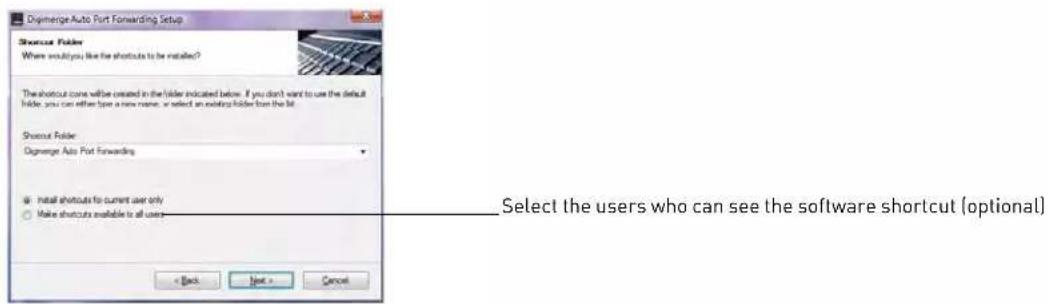
- Click the Next button and then click Finish to complete the software installation.

- Double-click the Auto Port Forwarding shortcut ( ) is done by your desktop to start the program.
Obtaining Your Router Model Number and Version
On most routers, the model and version number can be found underneath the router, printed on a sticker.
Example

Configuration

You must have the following before you configure the software:
- Your router's model number and version number
- Your router's user name and password
- Your device's IP address
- Your device's port numbers that require port forwarding
Initial Startup: Select Language
- Click the Language drop-down menu and select a language (English, French, Spanish). Click the Start button to continue.

- If software updates are available, click the Download Now button in the top-right corner.
- Run the update file and install the latest version of the software.
Step 1: Populate the Router Database
The Auto Port Forwarding Wizard automatically populates a list of current routers, and detects the number of connected routers.
- Click the Next button after the software detects your router configuration.

Step 2: Enter your Router Settings
- Under the Router drop-down list, select the model of your router. OR
- Click the Search button [] to enter the name of your router model.
NOTE: Click the Auto Detect button ( ) if you have a Linksys or Netgear router (works with most Linksys or Netgear models).

- Under Router IP, click the Detect Router IP button ( ).
- The router's IP populates in the blank field. Click OK to exit the prompt.
- Under Username and Password, enter the router's username and password.
- Optional: Under HTTP Type (default http://) and HTTP Port (default, 80), you may have to change the values depending on your router model. Consult your router manual for details.

- Under IP, enter the IP address of your device.
NOTE: The IP is usually found in the information window of your NVR.
-
Under Port, enter the NVR's HTTP Port (by default, port 80).
-
Under 2nd Port, enter the NVR's Client Port (by default, port 35000).
-
Click Next to continue.
Step 3: Update the Router Settings
1. Click the Update Router button.
- You will see your router window open. The Auto Port Forwarding Wizard automatically populates your router with the relevant information. This will take a few moments.

- Close the update window when the update finishes.
Step 4: Test your Connection
- Click the Test Your Connection button.
- Your system's default browser opens and connects to your device
NOTE: Ensure that Internet Explorer is your system's default internet browser.
NOTE: A window opens that prompts you to enter in your NVR's user name and password (do not enter your DDNS log in information).
NOTE: ActiveX warnings may appear. Accept all ActiveX installation warnings to connect to your system.
Configuring Multiple Routers
Your network may have two or more connected routers. During the initial launch of the auto port forwarding wizard, the program scans the network to detect the number of connected routers.
To check for multiple routers:
- Click the Detect Multiple Router s button().
- A list of connected routers populates in the window.
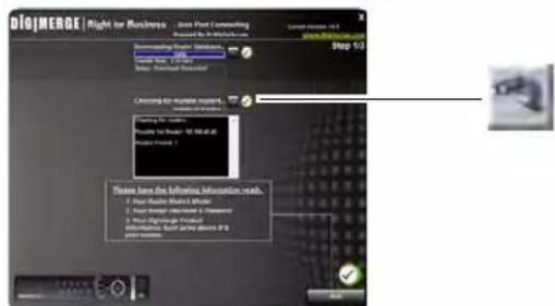
- The "Possible 1st Router" refers to the router directly connected to your system. This is the router that requires the port forward information.
- The "Possible 2nd Router" refers to the router immediate to the internet connection. This is the router that requires you to configure a DMZ host connection.
Scenario A: Router/Modem Combination + Router
- You may have a router/modem combination, with a second router in your network.
Scenario B: Multiple Routers
- You may have two routers in your network.

flowchart
graph TD
    A["Internet"] --> B["Modem"]
    B --> C["Router 2"]
    C --> D["Router 1"]
    D --> E["NVR System"]
    C --> F["DMZ IP"]
    D --> G["Port Forward port 80 & 554 to Router 1"]
    F --> H["Computer"]
    G --> H
    H --> I["EXAMPLE"]
    I --> J["LinkSYS by Cisco"]
    J --> K["Applications & Gaming"]
    K --> L["Setup"]
    L --> M["Windows"]
    M --> N["Security"]
    N --> O["Access Instructions"]
    O --> P["Applications & Gaming"]
    P --> Q["Administration"]
    Q --> R["Home"]
    R --> S["Port Route Forward"]
    S --> T["Port Trading"]
    T --> U["DMZ"]
    U --> V["Enable Enable"]
    V --> W["DIZ Node P Address"]
    W --> X["192.168.1.100"]
    X --> Y["Server Settings"]
    Y --> Z["Cancel Changes"]
    Z --> AA["CISCO"]
    AA --> AB["IP Address: 192.168.1.100 (Assigned by Router 2)"]
    AB --> AC["D-Link"]
In both scenarios, the router that is immediate to the internet connection (Router 2 in illustration) must act as a "bridge" to another router (Router 1 in illustration). The Auto Port Forwarding Wizard must connect to Router 1.
A proper DMZ configuration in Router 2 allows all incoming traffic going through Router 2 to automatically pass to Router 1. Router 2 acts as a "dummy" router and passes all the incoming data onto Router 1. Router 1 is the router that needs the port forwarding information.
Configuring a DMZ host connection
- Connect to "Router 1" on your network (referred to as "Possible 1st Router" in the Auto Port Forwarding Wizard). Obtain the IP address of Router 1. Usually this can be found in the "Status" section of your router menu. The IP should begin with "192.168...."This IP address is your DMZ IP.
- Enter the IP address obtained from Router 1 into the DMZ section of Router 2.
- Once you have configured Router 2 with a DMZ connection, run the Auto Port Forwarding Wizard to begin auto port forwarding to Router 1.
- Consult your router's owner's manual for details on configuring DMZ settings.
Example
DMZ stands for Demilitarized Zone. Enabling a DMZ IP on your router enables one of the routers to pass information onto the second router.

Locating your Router IP - The Status Page
The "Status Page" of a router normally includes the router's vital information such as the IP address.
EXAMPLE

APPENDIX D: SETTING UP DDNS SERVICE
Digimerge offers a free DDNS service for use with your NVR. A DDNS account allows you to set up a web site address that points back to your local network. The following outlines how to set up your free DDNS account.
To setup your free Digimerge DDNS account:
- In your browser, go to http://ddns.digimerge.net and click Create Account.
- Complete the Account Information fields with your personal information. Complete the Warranty Information with your purchase details (optional).
-
Complete the System Information fields:
-
Product License: Select your product model from the Product License drop down menu (i.e. DNR200).
- ←Product Code→ - ←MAC Address→: Enter the MAC address of your NVR. To find the MAC address, press the Enter button on the remote control OR left click on the screen, enter the admin password (default: 000000), and then
click
- URL Request: Choose a URL for your DDNS connection (i.e. your name, your company or business name, or anything of your choice).

Create a DDNS account
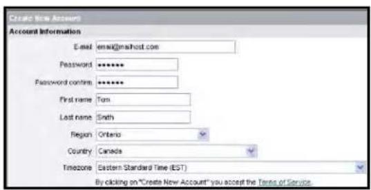
Enter personal information
- Once the information has been entered, click Create New Account.
- Your Account information will be sent to you at the email Address you used in Step 2.

System information
You will need this information for remote access to your system. Record your information below:
| User name: | |
| Domain name*: | |
| Password: |
How Do I Enable DDNS On My System?
Once you have registered for free DDNS service, use the information in the confirmation email to configure DDNS settings on your system.
To enable DDNS on your system:
- In live view, right-click and then click Mai n Menu. Login using the admin account if prompted (default user name is admin and default password is 000000).
- Click Setting→Network.
- Click Network Setting.

- Check DDNS.
- Double-click DDNS.

-
Configure the following:
-
Ensure Enable is checked. The checkbox will be white when DDNS is enabled.
- Under Domain Name, enter the Domain Name from the confirmation email you received after registering for DDNS.
- Under User ID, enter the User Name from the confirmation email.
-
Under Password, enter the Password from the confirmation email.
-
Click OK.
- Click Save.
NOTE: It may take between 10\~15 minutes for the DDNS server to update with your new DDNS address.
Connecting to your system using DDNS
NOTE: You must port forward ports on your router to NVR's IP address (by default, ports 35000 and 80) to connect to your system over the Internet.
Now that you have set up your system for DDNS, use the following address formats to connect:
CMS Software or Mobile Apps
tomsmith.digimerge.net
DDNS address
- For details on the CMS Software, see "DigiNet NVR Central Management Software" on page 39.
- For details on mobile apps, see "Mobile Connectivity" on page 61.
Internet Explorer
http://
http://tomsmith.digimerge.net:80
DDNS address
Colon
HTTP port number
- For details, see “Remote Viewing on Internet Explorer” on page 57.
APPENDIX E: REMOTE FIRMWARE UPGRADE
To perform a firmware upgrade over the LAN or Internet, a Config Tool is provided on the CD or www.digimerge.com. In an effort to continuously improve the functionality of our products, firmware upgrades are available as a free download on www.digimerge.com, as they are released.
NOTE: The Config Tool is supported on PC only. You may also upgrade the firmware using the NVR's local menus (see "Updating Firmware" on page 21).
Installing a Firmware Upgrade Over the LAN
Prerequisites:
- Connect your NVR to a router or switch on your network.
- Download a firmware upgrade from www.digimerge.com, if one is available. Extract the contents.
To perform a firmware upgrade over the LAN:
- Download the Config Tool from www.dig imerge.com.
- Extract the contents into a folder.
- Open the folder and right-click ConfigTool.ex e and Run as administrator. If a Windows Firewall warning appears, click Allow Access. The Config Tool scans your LAN for NVR's.
- Click Upgrade.
![ConfigTool Server List SR | 12 Address: 10.0.0.19 2 2003-4d1.207 9403/84 5000 255.250.255.0 10.0.0.1 3001.6d1.2 90.92 at 9c:47.1b 90.92 at 8c:47.1b WbP-7 WbP-7 109 109 Click Upgrade Up: For run click "login" button directly and then input corresponding information to login. 17 Version [All] Upgrade Refresh Login Layout](/content/2026/05/1002354/images/3d6463de71c7e6162b8e4605c4e63c5c02066d8d15c4960af2fea809993d3683.jpg)
- Check any NVR's you would like to upgrade.
-
Click Open. Select the upgr ade firmware file (.bin).
-
Click Upgrade. Wait for the upgrade to complete. Do not power off the system or disconnect the power cable during upgrade. The system will restart when the upgrade is complete.

Installing a Firmware Upgrade Over the Internet
Prerequisites:
- Port forward the Client Port (default: 35000) on the NVR's local router.
- Obtain the public IP address of the NVR.
- Download a firmware upgrade from www.digimerge.com, if one is available. Extract the contents.
To perform a firmware upgrade over the Internet:
- Download the Config Tool from www.digimerge.com.
- Extract the contents into a folder.
- Open the folder and right-click ConfigTool.ex e and Run as administrator.
- Click Login.
- Under IP Address, enter the public IP address of the NVR. Edit the User Name, Password, or Port if these have been changed from the default values.

- Click Login. The Config Tool logs in to the NVR.
- Click System Upgr ade.
-
Click Open. select the firmware file (.bin).
-
Click Upgrade. Wait for the upgrade to complete. Do not power off the system or disconnect the power cable during upgrade. The system will restart when the upgrade is complete.
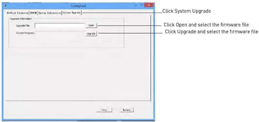
APPENDIX F: HARD DRIVE INSTALLATION
The system comes with one or more pre-installed 3.5" SATA hard drives. You can install up to two hard drives up to a maximum size of 3TB each (for a maximum total storage of 6TB).
Installing a Hard Drive

Make sure that the system is OFF and ALL power adapters have been disconnected before removing/installing the hard drive.
To remove the hard drive:
- Power off the system, and unplug all cabling / wiring from the system.
- Pull up on the hard drive door latch to unlock the hard drive compartment.

- Pull the hard drive compartment out of the system.

natural_image
Close-up of a black electronic device with a blue plastic panel and an arrow pointing to its side (no visible text or symbols)-
Place the hard drive upside down on a surface.
-
Place the hard drive compartment over the hard drive with the door facing away from the SATA connectors. Insert hard drive screws (x4) to secure the hard drive to the hard drive compartment.
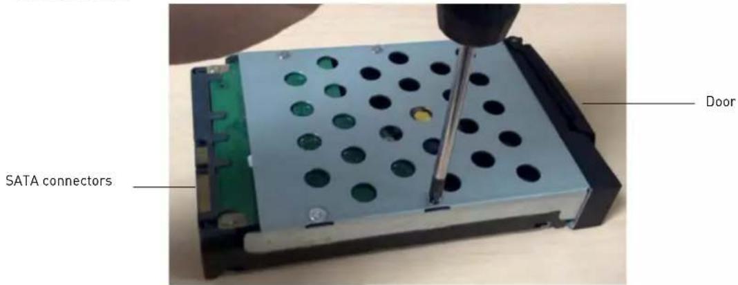
- Hold the hard drive and compartment in a vertical position with the SATA connectors near the bottom of the unit, and fully insert it into the system.

- Push the hard drive door latch in to lock the hard drive in place.
NOTE: After installation, you must format the hard drive in order to use it with the system. See "Formatting the Hard Drive" on page 106.
Removing the Hard Drive

Make sure that the system is OFF and ALL power adapters have been disconnected before removing/installing the hard drive.
To remove the hard drive:
- Power off the system, and unplug all cabling / wiring.
- Pull up on the hard drive door latch to unlock the hard drive compartment.

- Pull the hard drive compartment out of the system.
- Place the hard drive and hard drive compartment upside down on a surface. Remove the hard drive screws (x4) and remove the compartment from the hard drive.

- Re-insert the hard drive compartment into the unit.
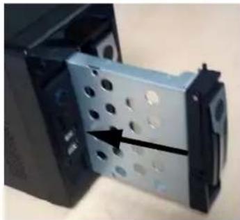
natural_image
Close-up of a mechanical component with a metallic bracket and perforated plate, showing a black arrow indicating direction (no text or symbols visible)- Push the hard drive door latch in to lock into place.
Formatting the Hard Drive
After installing a new hard drive, you must format it before the system can recognize it.
ATTENTION: Formatting the HDD erases all data on the hard disk. This step cannot be undone. System settings will not be erased.
To format a hard drive:
- From Live View, right-click and select Main Menu→Advanc ed→HDD Management.
-
Under HDD No., select the hard drive you would like to format. Information about the hard drive appears in the lower section of the menu.
-
Under Set to, select Format.
Click Apply. Click OK to confirm. Wait for the hard drive to format. Hard drives become Read/Write hard drives by default when formatted.
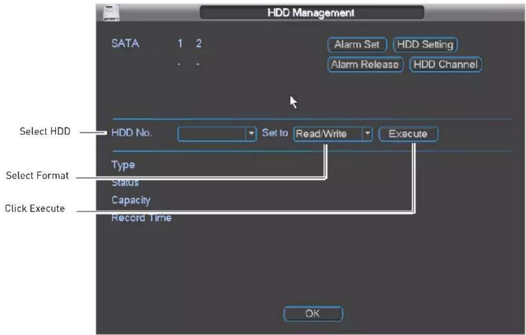
TROUBLESHOOTING
When a malfunction occurs, it may not be serious and can be corrected easily. The following describes the most common problems and solutions. Please refer to the following before calling Digimerge Technical Support:
| Error Possible Causes Solutions | ||
| • NVR is not receiving power, or is not powering up | • Cable from power adapter is loose or is unplugged | • Confirm that all cables are connected correctly• Confirm that the power adapter is securely connected to the back of the unit |
| • Cables are connected, but NVR unit is not receiving sufficient power | • Confirm that the unit is powered on (LED indicators on the front should be ON)• If the unit is connected through a power bar or surge protector, try bypassing the bar and connecting the power directly to the wall outlet• Confirm that there is power at the outlet:• Connecting the power cable to another outlet• Test the outlet with another plugged device (such as an electric calculator or phone charger) | |
| • There is no picture on selected channels / camera picture is not being displayed | • PoE power adapter is not connected | • Make sure the 48V DC power adapter is connected to the NVR or the cameras will not receive power from the PoE Ports |
| • Camera cables are loose or have become disconnected | • Disconnect and reconnect the cable at the NVR and at the Camera• Try moving the camera to another channel or use another cable• If your cameras are not using PoE, make sure they are using the correct power source according to the specifications provided by the manufacturer | |
| • Camera/NVR connection to LAN has become interrupted | • Make sure your cameras are connected to the same LAN as the NVR• Make sure any routers or switches in between the NVR and IP cameras are powered on | |
| • Remote control is not detected by the system | • Batteries in the remote control are drained• There are no batteries in the remote control | • Install 2 fresh AAA batteries in the remote control |
| • Hard drive is not detected by the system | • Hard drive cables are loose or not properly connected | • Remove the housing and check that hard drive cables are firmly connected |
| • Hard drive has not been initialized (formatted) by the system | • For details, see “Formatting the Hard Drive” on page 106 | |
| • There is no hard drive in the system | • Open the housing and install a 3.5" SATA hard drive | |
| • Hard drive is full and the unit is no longer recording | • Overwrite is not enabled • From the Main Menu, select General. Beside HDD Full, select Overwrite. Click OK to save settings. This enables the system to continuously record by overwriting data once the hard drive is full | |
| • Mouse not detected by system | • Mouse cable is not firmly connected to the system | • Firmly connect the mouse cable to the system |
| • Mouse is not connected to the system | ||
| • System needs to be reset • Re-connect the power cord to restart the system. | ||
| • My system does not seem to be recording | • Recording may be disabled • Right-click in live view, and click Record. Ensure that each channel is set to Schedule or Manual. If schedule is selected, make sure schedule settings are correct under Setting→Schedule.ATTENTION: For security, it is highly recommended to keep Continuous Recording ON at all times | |
Remote Connectivity Troubleshooting
| Error Possible Causes Solutions | ||
| Cannot connect to the NVR over the Internet | Ports not forwarded • Port forward | the HTTP port (default: 80) and Client port (default: 35000) |
| DDNS Setup not completed • Register for a DDNS account. For details, see “Appendix D: Setting Up DDNS Service” on page 97 | ||
| Ports are blocked by Internet Service Provider (ISP) | Some ISP’s block port 80. Reassign the HTTP port to anything above 1026. Re-complete port forwarding using the newly assigned port | |
| Multiple routers installed in local network | If you have multiple routers, additional setup may be required. For details, see “Configuring Multiple Routers” on page 94. | |
| Could connect to system previously, but no longer can | NVR internal IP address has changed | This can occur if your router resets due to power failure. Set up a fixed IP address for your NVR. For details, see “Configuring DHCP or Fixed IP Address” on page 25 |
| Cannot connect to the NVR using a smartphone or tablet | IP address used from outside local network | Use the DDNS address to connect to the NVR using a mobile application (e.g. tomsmtih.digimerge.net) |
| Router is blocking DDNS connection from internal network | Turn off WiFi connection and attempt to connect using 3G or mobile network | |
DIGIMERGE | Right for Business
Need Help?
Please make sure to visit our website www.digimerge.com to receive product updates and information.
3 Easy Ways To Contact Us

natural_image
Woman in orange sleeveless top using a laptop with a drink, sitting on a bed (no visible text or symbols)
natural_image
Elderly couple sitting together, one using a laptop (no visible text or symbols)
natural_image
Man in lab coat talking on phone in a laboratory setting (no visible text or symbols)Online:
Product support is available 24/7 including product information, user manuals, quick start up guides and FAQ's at www.digimerge.com
By Email:
Technical support (for technical/installation issues) tech@digimerge.com
By Phone:
North America: 1-866-816-5919 Technical support (for technical/installation issues) Mon-Fri 8.00 am to 8.00pm EST
We welcome your feedback at info@digimerge.com
For more information, visit www.digimerge.com

- DIGIMERGE | Right for Business
- DNR200V Series
- Network Video Surveillance Recorder
- CAUTION
- RISK OF ELECTRIC SHOCK DO NOT OPEN
- Important Safeguards
- Installation
- Service
- G
- Use
- General Precautions
- FCC CLASS A NOTICE
- NOTE
- Features
- TABLE OF CONTENTS
- Getting Started .... 1
- Basic Setup 2
- Front Panel 3
- Rear Panel 4
- Remote Control.... 5
- Using the System 7
- Setting the Time 12
- Recording.... 13
- Search (Playback).... 14
- Backup 16
- Using the Main Menu 20
- Setting 23
- Device Search 30
- Advanced 32
- Shutdown 38
- DigiNet NVR Central Management Software 39
- Adding a NVR using a DDNS address 42
- Using Alarm Rec (Event Search) 45
- Using Playback Mode ....46
- Configuring Monitoring Tasks and Projects 47
- Using E-Map 50
- Configuring the CMS 52
- Adding User Accounts to the CMS 54
- Multi-Monitor Support 55
- Remote Viewing on Internet Explorer 57
- Prerequisites 57
- Mobile Connectivity 61
- iPhone 61
- iPad 67
- Android Phones 72
- Android Tablets 78
- Appendix A: System Specifications 85
- Appendix B: Setting up Remote Viewing 87
- Appendix C: Auto Port Forwarding Wizard 90
- Configuration 91
- Appendix D: Setting Up DDNS Service 97
- Appendix E: Remote Firmware Upgrade 100
- Appendix F: Hard Drive Installation.... 103
- Troubleshooting 107
- GETTING STARTED
- Connect a Monitor
- Connect the Mouse
- Connect the Ethernet Cable
- Connect the Power Adapters
- FRONT PANEL
- REAR PANEL
- REMOTE CONTROL
- Mouse Control
- Left -Button:
- Right-Button:
- USING THE SYSTEM
- Password
- On-Screen Display
- Display Area:
- Channel Name
- Channel Status Icons:
- Using the Quick Menu
- Adjusting Color Settings
- To adjust color settings:
- OR
- Using the Navigation Bar
- To open the Navigation bar:
- Using the Camera Toolbar
- To access the Camera Toolbar:
- Using Quick Playback
- To use Quick Playback:
- Using Digital Zoom in Live Display
- Using Real-time Backup
- To use Real-time Backup:
- Using the Virtual Keyboard
- SETTING THE TIME
- To set the date and time:
- Click Save.
- RECORDING
- The system supports the following recording types:
- SEARCH (PLAYBACK)
- Playing Back Video from the Hard Drive
- BACKUP
- Formatting the USB Device
- To format a USB device:
- Backing up Video
- Click Backup.
- Configure your search options:
- Using Video Clip Backup
- To use Video Clip Backup:
- Viewing Backup Files
- To view backup video files using the Player (PC only):
- USING THE MAIN MENU
- To open the Main Menu:
- Info
- To search for system logs:
- Updating Firmware
- Remote Device Info
- Setting
- The General sub-menu contains the following options:
- To configure recording quality settings:
- Schedule
- Configuring the Recording Schedule
- Configuring Pre-Recording and Mirror Recording
- To configure pre-recording and mirror recording:
- Configuring Holidays
- To configure holidays:
- Network
- Configuring DHCP or Fixed IP Address
- Configuring System Ports
- You must port forward the TCP (Client) Port and HTTP Ports to enable remote access to the system.
- To configure ports:
- Configuring NTP
- To sync the system with a time server:
- Configuring DDNS
- Prerequisites:
- To configure DDNS settings:
- Connecting to your system
- To configure Email Alerts:
- To configure switch settings:
- Motion
- Configuring Motion Detection Events
- To configure display settings:
- Default
- To reset the system to factory default settings:
- Device Search
- Adding Cameras from the LAN
- To manually add a camera to the NVR:
- Editing Cameras
- To edit cameras:
- Deleting Cameras
- Advanced
- Formatting Hard Drives
- To format a hard drive:
- Selecting Hard Drive Types
- To select hard drive types:
- Configuring Hard Drive Group Settings
- To configure hard drive group settings:
- Configuring eSATA External Hard Drives
- To configure eSATA hard drives:
- Warning
- To configure system error actions:
- Record
- To configure manual recording:
- Account
- Adding Accounts
- Modifying Accounts
- To modify account settings:
- To modify an account password:
- Deleting Accounts
- Adding Groups
- To add a group:
- Deleting Groups
- Modifying Groups
- Auto Maintain
- To configure Auto Maintain settings:
- Config Backup
- To export the system configuration to a USB flash drive:
- Click Export.
- To import a saved system configuration:
- Shutdown
- To access the Shutdown menu:
- DIGINET NVR CENTRAL MANAGEMENT SOFTWARE
- System Requirements
- Prerequisites
- Installing DigiNet NVR CMS
- To start the software:
- Adding a NVR from the Local Area Network (LAN)
- To add a NVR:
- Adding a NVR using a DDNS address
- To add a NVR using a DDNS address:
- Click Manual Add.
- Configure the following:
- Live View Toolbar:
- Using Alarm Rec (Event Search)
- To use Alarm Rec:
- Check Search.
- Using Playback Mode
- To use playback mode:
- Configuring Monitoring Tasks and Projects
- Configuring Tasks
- Click Monitor Task.
- Configuring Projects
- To configure a project:
- Running Tasks and Projects
- Using E-Map
- Configuring E-Map
- To configure the E-Map:
- Opening Cameras from E-Map
- Configuring the CMS
- Configuring CMS Options
- Changing the CMS Admin Password
- Adding User Accounts to the CMS
- To add a user account to the CMS:
- Multi-Monitor Support
- Opening Cameras in Secondary Monitors
- Managing Secondary Monitors
- To manage secondary monitors:
- REMOTE VIEWING ON INTERNET EXPLORER
- To view your system using Internet Explorer:
- Camera Controls:
- Live Vie w Toolbar:
- PTZ Controls
- Using Search Mode in IE (Playback)
- To access recorded video from your NVR:
- MOBILE CONNECTIVITY
- iPhone
- Connecting to your NVR on an iPhone
- Tap Add→Manually Add.
- Configure the following:
- Tap Save.
- Tap
- Tap Live Preview.
- DigiNet NVR Interface
- Viewing Videos with Local File
- To access Local File:
- Using Playback Mode on iPhone
- Enabling Push Notifications
- To enable Push Notifications:
- Device Manager
- To access Device List:
- To edit an NVR:
- To delete an NVR:
- iPad
- Connecting to your NVR on an iPad
- Tap Sav e.
- DigiNet NVR HDInterface
- To access Device Manager:
- To modify an NVR:
- Using Playback Mode on iPad
- Android Phones
- Compatible Devices
- Connecting to your NVR on an Android Phone
- Tap Device Manager.
- Viewing Snapshots and Videos with Local Files
- To access Local Files:
- Using Playback Mode on Android Phones
- Android Tablets
- Connecting to your NVR on an Android Tablet
- DigiNet NVR HD Interface
- Using Playback Mode on Android Tablets
- APPENDIX A: SYSTEM SPECIFICATIONS
- System
- Inputs/Outputs
- Display
- APPENDIX B: SETTING UP REMOTE VIEWING
- What Do I Need?
- Network Setup / Remote Access Overview
- To setup remote viewing:
- How Do I Find My IP and MAC addresses?
- To find your IP and MAC address:
- Finding Your External IP Address
- How Do I Enable Port Forwarding?
- APPENDIX C: AUTO PORT FORWARDING WIZARD
- To install the Auto Port Forwarding Wizard:
- Obtaining Your Router Model Number and Version
- Example
- Configuration
- Initial Startup: Select Language
- Step 1: Populate the Router Database
- Step 2: Enter your Router Settings
- Step 3: Update the Router Settings
- Click the Update Router button.
- Step 4: Test your Connection
- Configuring Multiple Routers
- To check for multiple routers:
- Scenario A: Router/Modem Combination + Router
- Scenario B: Multiple Routers
- Configuring a DMZ host connection
- Locating your Router IP - The Status Page
- APPENDIX D: SETTING UP DDNS SERVICE
- To setup your free Digimerge DDNS account:
- How Do I Enable DDNS On My System?
- To enable DDNS on your system:
- Connecting to your system using DDNS
- CMS Software or Mobile Apps
- Internet Explorer
- APPENDIX E: REMOTE FIRMWARE UPGRADE
- Installing a Firmware Upgrade Over the LAN
- To perform a firmware upgrade over the LAN:
- Installing a Firmware Upgrade Over the Internet
- To perform a firmware upgrade over the Internet:
- APPENDIX F: HARD DRIVE INSTALLATION
- Installing a Hard Drive
- To remove the hard drive:
- Removing the Hard Drive
- Formatting the Hard Drive
- TROUBLESHOOTING
- Remote Connectivity Troubleshooting
- Need Help?
- Easy Ways To Contact Us
- Online:
- By Email:
- By Phone:
Brand : Digimerge
Model : DN204P1V4
Category : Security Camera