
SPK-C818 - Loudspeaker Kramer - Free user manual and instructions
Find the device manual for free SPK-C818 Kramer in PDF.


| Product Type | Ceiling Speaker |
| Brand | Kramer |
| Model | SPK-C818 |
| Woofer Size | 8 inches |
| Tweeter Size | 1 inch |
| Power Handling (RMS) | 60 W |
| Impedance | 8 Ω |
| Frequency Response | 70 Hz - 20 kHz |
| Sensitivity | 88 dB |
| Dimensions (Diameter x Depth) | 280 mm x 180 mm |
| Weight | 2.5 kg |
| Material | Steel backcan, plastic baffle |
| Color | White |
| Installation Type | Spring-loaded clamps |
| Connector Type | Euroblock (removable screw terminal) |
| Application | Background music, paging, PA |
| Certifications | CE, RoHS |
| Included Accessories | Cut-out template, mounting screws, paint shield |
| Warranty | Limited 5 years |
Frequently Asked Questions - SPK-C818 Kramer
User questions about SPK-C818 Kramer
0 question about this device. Answer the ones you know or ask your own.
Ask a new question about this device
Download the instructions for your Loudspeaker in PDF format for free! Find your manual SPK-C818 - Kramer and take your electronic device back in hand. On this page are published all the documents necessary for the use of your device. SPK-C818 by Kramer.
USER MANUAL SPK-C818 Kramer
ESD™ Complete K-overage
Ceiling Speaker
Contents
1 Introduction 1
2 Getting Started 2
2.1 Achieving the Best Performance 2
3 Overview 3
3.1 Defining the ESD Ceiling Speaker 5
4 Installing the ESD Ceiling Speaker 6
4.1 Choosing the Best Location 6
4.2 The Input Pinout 6
4.3 Determining the Number of Speakers Needed and their Location 7
4.4 Preparing the ESD Ceiling Speaker for Operation 9
4.5 Installing the Tile Size Speaker 9
4.6 Installing the Half-Tile Size Speaker 11
5 Technical Specifications 14
Figures
Figure 1: Tile Size ESD Ceiling Speaker (that fits into the ceiling) 4
Figure 2: ESD Ceiling Speaker 5
Figure 3: ESD Ceiling Speaker Input Pinout 6
Figure 4: Speaker Location in a Room—using ESD Speakers vs. using Standard Ceiling Speakers 7
Figure 5: Connecting One Stereo Speaker 8
Figure 6: Connecting Two Mono Speakers 8
Figure 7: Fitting the Tile Size Speaker 10
Figure 8: Securing the Speaker to a Ceiling Anchor Point 10
Figure 9: Placing the Ceiling Mounting Bracket 11
Figure 10: Fitting the Half-Tile Size Speaker 12
Figure 11: Replacing the Ceiling Tile 12
Figure 12: ESD Ceiling Speaker in a Boardroom Setup 13
1 Introduction
Welcome to Kramer Electronics! Since 1981, Kramer Electronics has been providing a world of unique, creative, and affordable solutions to the vast range of problems that confront the video, audio, presentation, and broadcasting professional on a daily basis. In recent years, we have redesigned and upgraded most of our line, making the best even better!
Our 1,000-plus different models now appear in 11 groups that are clearly defined by function: GROUP 1: Distribution Amplifiers; GROUP 2: Switchers and Matrix Switchers; GROUP 3: Control Systems; GROUP 4: Format/Standards Converters; GROUP 5: Range Extenders and Repeaters; GROUP 6: Specialty AV Products; GROUP 7: Scan Converters and Scalers; GROUP 8: Cables and Connectors; GROUP 9: Room Connectivity; GROUP 10: Accessories and Rack Adapters and GROUP 11: Sierra Products.
Congratulations on purchasing your Kramer ESD™ (Equal Sound Dispersion) Ceiling Speaker, which is ideal for overhead distributed audio for professional applications (music and speech) and educational applications (mainly speech), as shown here:
| Complete K-overage ESD® Ceiling Speakers: Applications | |
| SPK-C812, SPK-C813, SPK-C814, SPK-C815, SPK-C820 | SPK-C816, SPK-C817, SPK-C818, SPK-C819 |
| Business and professional environments (such as presentations) | Educational environments (such as lectures) |
| Conference rooms and boardroomsHotel lobbies and large office buildingsRetail storesAirports | University lecture hallsClassroomsPresentation venues |
2 Getting Started
We recommend that you:
- Unpack the equipment carefully and save the original box and packaging materials for possible future shipment
- Review the contents of this user manual Use Kramer high performance high resolution cables

Go to http://www.kramerelectronics.com to check for up-to-date user manuals, application programs, and to check if firmware upgrades are available (where appropriate).
2.1 Achieving the Best Performance
To achieve the best performance:
- Use only good quality connection cables to avoid interference, deterioration in signal quality due to poor matching, and elevated noise levels (often associated with low quality cables)
- Avoid interference from neighboring electrical appliances that may adversely influence signal quality
- Position your Kramer Speakers away from moisture, excessive sunlight and dust
3 Overview
The ESD ^™ (Equal Sound Dispersion) Ceiling Speaker is a high-performance complete K-overage ESD ceiling speaker that can be mounted on the ceiling and appears as a suspended ceiling tile.
The ESD ceiling speaker is constructed with a central driver and four pivoting tweeters and is housed in an enclosed shallow enclosure.
The Kramer complete K-overage ESD provides unmatched sound response in a suspended ceiling device for the professional (PRO) and educational (EDU) markets. This means that you get the sound you need but with a reduced number of speakers.
The ESD ceiling speaker features:
- Complete K-overage ESD™ – a patent pending design with 4 pivoting tweeters that direct the sound, based on the room environment, for equal sound dispersion (ESD)
- Wide 180^ sound dispersion
- One Kramer ESD speaker that replaces multiple standard speakers for quick and easy installation
- Excellent bass response that is optimized for music and high-quality voice reproduction
• 4 pivoting tweeters, 3/4" (6Ω) with silk domes
• A polypropylene cone woofer (8Ω)
• A 40W RMS power rating - Smooth frequency response
• A shallow 4-inch depth (approx. 100mm) - RoHS compliance
Compliance to RoHS means acting in full accordance with RoHS regulations that restrict the use of certain dangerous substances commonly used in electronic and electronic equipment - A choice of models: tile size or half-tile size, stereo or mono (see table below)
• A bass port for a bass reflex effect (for educational models)
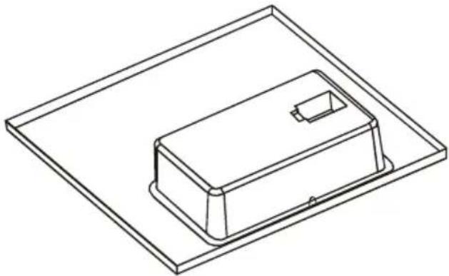
natural_image
Isometric line drawing of a rectangular electronic component with a small protrusion, placed on a flat base (no text or symbols)Figure 1: Tile Size ESD Ceiling Speaker (that fits into the ceiling)
The speaker is easily installed and is available in eight different models: PRO or EDU, stereo or mono, tile size or half-tile size configurations, and a slightly smaller size (for any region with suspended ceiling tiles of 595mm) as defined here:
| Complete K-ovage ESD® Ceiling Speakers Available Models | ||
| Model Name | Part Number | Description |
| Professional tile size stereo | SPK-C812 | Polypropylene woofer, surrounded with rubber2 left and 2 right silk dome tweetersNo bass reflex |
| Professional tile size mono | SPK-C813 | Polypropylene woofer, surrounded with rubber4 silk dome tweetersNo bass reflex |
| Professional half-tile size stereo | SPK-C814 | Polypropylene woofer, surrounded with rubber2 left and 2 right silk dome tweetersNo bass reflex |
| Professional half-tile size mono | SPK-C815 | Polypropylene woofer, surrounded with rubber4 silk dome tweetersNo bass reflex |
| Educational tile size stereo | SPK-C816 | Paper cone woofer, surrounded with rubber2 left and 2 right Ti pivoting tweeters, installer adjustedBass reflex |
| Educational tile size mono | SPK-C817 | Paper cone woofer, surrounded with rubber4 Ti pivoting tweeters, installer adjustedBass reflex |
| Educational half-tile size stereo | SPK-C818 | Paper cone woofer, surrounded with rubber2 left and 2 right Ti pivoting tweeters, installer adjustedBass reflex |
| Educational half-tile size mono | SPK-C819 | Paper cone woofer, surrounded with rubber4 Ti pivoting tweeters, installer adjustedBass reflex |
| Professional Tile size stereo (for 595mm tiles) | SPK-C820 | Polypropylene woofer, surrounded with rubber2 left and 2 right silk dome tweetersNo bass reflex |
3.1 Defining the ESD Ceiling Speaker
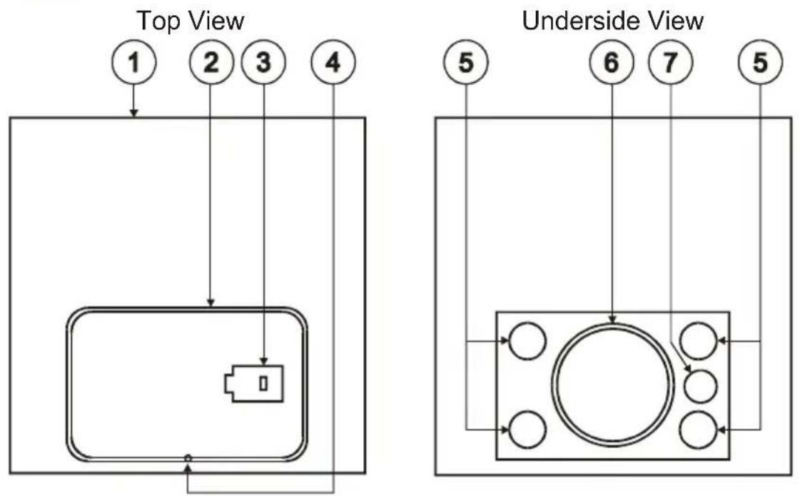
Figure 2 defines the ESD Ceiling Speaker:
flowchart
graph TD
    A["Top View"] --> B["Device Layout"]
    C["Underside View"] --> D["Device Layout"]
    style A fill:#f9f,stroke:#333
    style C fill:#f9f,stroke:#333
    style D fill:#ccf,stroke:#333
Figure 2: ESD Ceiling Speaker
| Flat Ceiling Speaker Features | ||
| # Feature Function | ||
| 1 | Speaker Tile Base | Half-tile size or tile size |
| 2 | Speaker Steel Enclosure Shallow fireproof enclosure | |
| 3 | INPUT Terminal Block Connector | Connect to the audio source (see Section 4.2) |
| 4 | Anchor Ring | Secure the speaker to the ceiling anchoring point |
| 5 | Tweeters (4) | Pivoting titanium or silk |
| 6 | Woofer Polypropylene or paper surrounded by rubber | |
| 7 | Bass Port For a bass reflex effect | |
4 Installing the ESD Ceiling Speaker
This section explains how to install the ESD Ceiling Speaker, that is:
- Choosing the best place to locate your speaker (see Section 4.1)
- Connecting the wires (see Section 4.2)
• Determining the number of speakers (see Section 4.3)
• Preparing the speaker for operation (see Section 4.4)
• Installing the tile size speaker (see Section 4.5)
• Installing the half-tile size speaker (see Section 4.6)
4.1 Choosing the Best Location
Ideally, locate the speakers above the main listening area. Before doing so, be sure that:
- The desired location is free of obstructions, such as electrical piping, AC ducts or water lines, and so on
• There is enough space behind the mounting surface for the speaker - The rear side of the speaker is not blocked by wall studs or other objects
4.2 The Input Pinout
Figure 3 illustrates the terminal block pinout for mono and stereo models respectively:
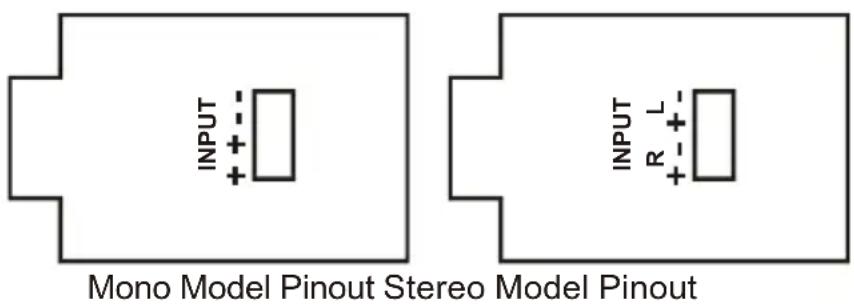
Figure 3: ESD Ceiling Speaker Input Pinout

The red wire connects to the + pin and the black wire connects to the - pin.
4.3 Determining the Number of Speakers Needed and their Location
When installed in a room with a standard ceiling height of 2.7m (8.8 feet), the optimal distance between the speakers is about 10 meters. The speaker should be installed lengthwise relative to the shape of the room. The example in Figure 4 shows the ESD Ceiling Speaker installed in a 10m x 5m room. A 10m x 5m room size requires only one ESD speaker for full room coverage rather than four standard ceiling speakers.
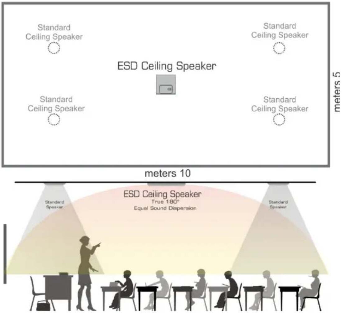
Figure 4: Speaker Location in a Room—using ESD Speakers vs. using Standard Ceiling Speakers
To achieve optimum sound quality and ESD (Equal Sound Dispersion):
- Select the appropriate output from the amplifier to use with the speaker (either stereo or mono)
- If the size of the room only requires a single speaker, we recommend using the mono/stereo speaker model for speech and music (see Figure 5)
- If the size of the room requires more than one speaker, use two mono speaker models. Connect the speakers to the left and right connectors of the amplifier, respectively (see Figure) 6
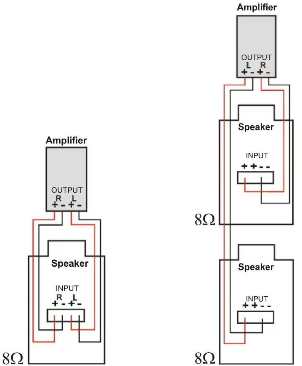
Figure 5: Connecting One Stereo Speaker
Figure 6: Connecting Two Mono Speakers
4.4 Preparing the ESD Ceiling Speaker for Operation
Once the location of the speaker is fixed, prepare the speaker for operation as follows:
- Move each of the pivoting tweeters outward in an angle that is suited to the room shape and size.
- Run the wires from the amplifier through the ceiling.
- Remove the ceiling tile at the place where you plan to install the speaker.
- Connect the speaker wires to the speaker terminals (see Figure 3) from the adjacent ceiling tile opening.
- Place the speaker temporarily in place, and test the audio quality.
- If you are satisfied, disconnect the amplifier and remove the speaker from the ceiling. If not, change the position of the tweeters and check the audio quality again until you are happy with the results.
- Fit the speaker grille over the speaker underside and tighten with screws.
To install the tile size speaker, see Section 4.5.
To install the half-tile size speaker, see Section 4.6
4.5 Installing the Tile Size Speaker
- Drop the speaker into the ceiling tile space. Make sure that you position the speaker lengthwise relative to the room shape (see Figure 7).
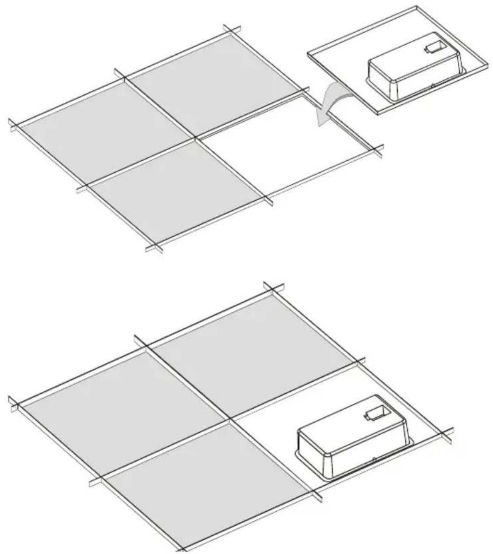
Figure 7: Fitting the Tile Size Speaker
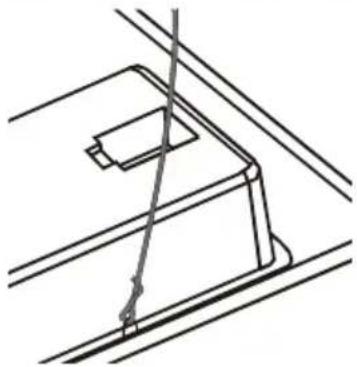
- Secure the speaker by connecting the speaker support ring to an independent secure ceiling anchor point (see Figure 8) as appropriate. The anchor prevents the speaker from falling if the tile itself comes out or falls apart.
natural_image
Pure technical line drawing of a mechanical assembly without any text, numbers, or symbolsFigure 8: Securing the Speaker to a Ceiling Anchor Point
- If required, daisy-chain the next speaker (see Section 4.3).
Note: Do not over-tighten the screws. It may cause damage to both the speakers and the surface.
4.6 Installing the Half-Tile Size Speaker
When installing the half-tile size model:
- Remove the ceiling tile.
-
Cut the ceiling tile in half (to 30x60cm).
-
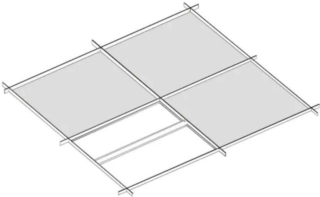
Place the ceiling mounting bracket (supplied with the half-tile unit only) between the ceiling rails, as illustrated in Figure 9.
natural_image
Isometric line drawing of a structural framework with four rectangular panels, no text or symbols presentFigure 9: Placing the Ceiling Mounting Bracket
- Drop the half-tile size speaker in the appropriate opening, so it is supported by the ceiling rails and the ceiling mounting bracket (see Figure 10). No screws are needed.
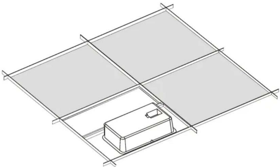
natural_image
Isometric line drawing of a solar panel installation with a central device and grid lines (no text or symbols)Figure 10: Fitting the Half-Tile Size Speaker
- Replace half of the ceiling tile (see Figure 11).
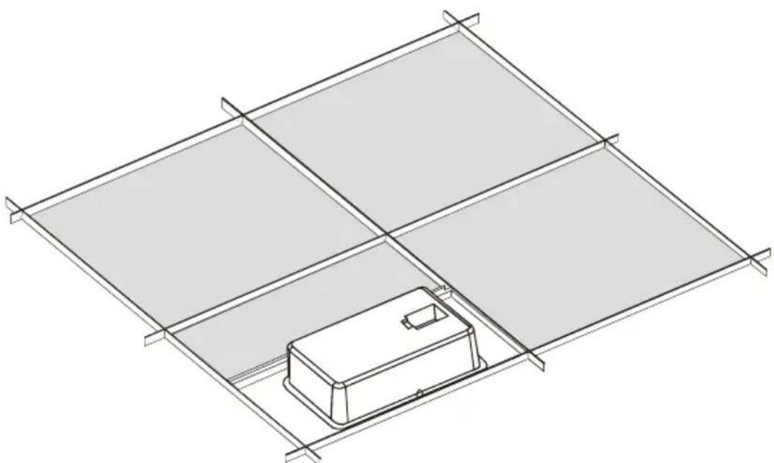
natural_image
Isometric line drawing of a solar panel array with a central device (no text or symbols)Figure 11: Replacing the Ceiling Tile
- Secure the speaker by connecting the speaker support ring to an independent secure ceiling anchor point (see Figure 8).
The anchor prevents the speaker from falling if the tile itself comes out or falls apart.
Figure 12 shows an example of how the ESD Ceiling Speaker can be installed in a boardroom setup:
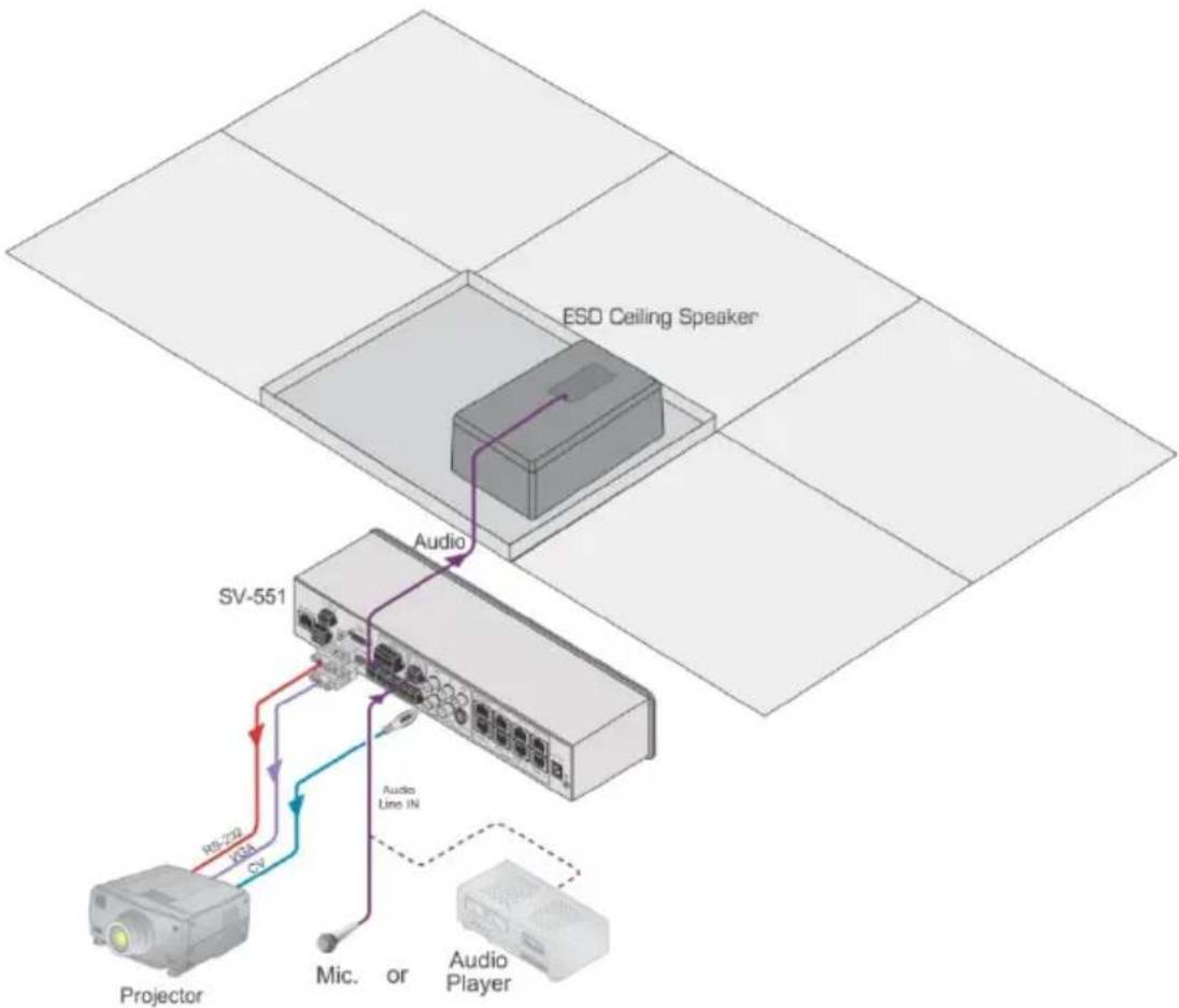
flowchart
graph TD
    A["ESD Ceiling Speaker"] -->|Audio| B["SV-551"]
    B -->|Audio Lines IN| C["Projector"]
    C -->|RS-722, I234, CV| B
    B -->|Mic. or Audio Player| D["Monitor"]
Figure 12: ESD Ceiling Speaker in a Boardroom Setup
5 Technical Specifications
| Technical Specifications of the PRO ESD Ceiling Speakers | |
| INPUT POWER: | 40W RMS; max. 80 W; continuous load: 40W (24Hr) |
| NOMINAL SENSITIVITY: | 87dB SPL @1m |
| CROSSOVER FREQUENCY: | 2kHz |
| MEAN SPL: | 87dB +/- 1dB @1W-1m |
| FREQUENCY RANGE: | Nominal: 80Hz-20kHz; max: 60Hz-20kHz |
| SPEAKER TYPE: | Two-way closed ceiling speaker |
| WOOFER: | 8" (203mm) polypropylene cone with rubber surround |
| TWEETER: 4 X 3/4" (19mm) silk dome pivoting tweeter | |
| IMPEDANCE: | Woofer: 8Ω; tweeter: 6Ω |
| SENSITIVITY: 87dB SPL @1W, | 1m |
| DIMENSIONS: | 30cm x 60cm x 10cm (half-tile size); 60cm x 60cm x 10cm (tile size);59.5cm x 59.5cm x 10cm (tile size) for any region with suspendedceiling tiles of 595mm |
| WEIGHT: | 6.3kg (13.9lbs) approx. (half-tile size); 6.5kg (14.3lbs) approx. (tilesize) |
| SHIPPING WEIGHT: | 7.8kg (17.2lbs) approx. (half tile); 8.0kg (17.6lbs) approx. (tile size) |
| ACCESSORIES: | Ceiling mounting bracket (supplied with half-tile size units only) |
| Specifications are subject to change without notice at http://www.kramerelectronics.com | |
| Technical Specifications of the EDU ESD Ceiling Speakers | |
| INPUT POWER: | 40W RMS; max. 80 WContinuous load: 40W (24Hr) |
| NOMINAL SENSITIVITY: | 90dB SPL @1m |
| CROSSOVER FREQUENCY: | 2kHz |
| MEAN SPL: | 90dB +/- 1dB @1W-1m |
| FREQUENCY RANGE: | Nominal: 150Hz-20kHz; max: 100Hz-20kHz |
| SPEAKER TYPE: | Two-way bass reflex closed ceiling speaker |
| WOOFER: | 8" (203mm) paper cone with rubber surround |
| TWEETER: | 4 X 1" (25mm) titanium dome pivoting tweeter |
| IMPEDANCE: | Woofer: 8Ω; tweeter: 6Ω |
| SENSITIVITY: 90dB SPL @1W, | 1m |
| DIMENSIONS: | 30cm x 60cm x 10cm (half-tile size); 60cm x 60cm x 10cm (tile size) |
| WEIGHT: | 6.3kg (13.9lbs) approx. (half-tile size); 6.5kg (14.3lbs) approx. (tile size) |
| SHIPPING WEIGHT: | 7.8kg (17.2lbs) approx. (half-tile size); 8.0kg (17.6lbs) approx. (tile size) |
| ACCESSORIES: | Ceiling mounting bracket (supplied with half-tile size units only) |
| Specifications are subject to change without notice at http://www.kramerelectronics.com | |
LIMITED WARRANTY
We warrant this product free from defects in material and workmanship under the following terms.
HOW LONG IS THE WARRANTY
Labor and parts are warranted for one year from the date of the first customer purchase.
WHO IS PROTECTED?
Only the first purchase customer may enforce this warranty.
WHAT IS COVERED AND WHAT IS NOT COVERED
Except as below, this warranty covers all defects in material or workmanship in this product. The following are no covered by the warranty:
- Any product which is not distributed by us or which is not purchased from an authorized Kramer dealer. If you are uncertain as to whether a dealer is authorized, please contact Kramer at one of the agents listed in the Web site www.kramerelectronics.com.
- Any product, on which the serial number has been defaced, modified or removed, or on which the WARRANTY VOID IF TAMPERED sticker has been torn, reattached, removed or otherwise interfered with.
- Damage, deterioration or malfunction resulting from:
i) Accident, misuse, abuse, neglect, fire, water, lightning or other acts of nature
ii) Product modification, or failure to follow instructions supplied with the product
iii) Repair or attempted repair by anyone not authorized by Kramer
iv) Any shipment of the product (claims must be presented to the carrier)
v) Removal or installation of the product
vi) Any other cause, which does not relate to a product defect
vii) Cartons, equipment enclosures, cables or accessories used in conjunction with the product
WHAT WE WILL PAY FOR AND WHAT WE WILL NOT PAY FOR
We will pay labor and material expenses for covered items. We will not pay for the following:
- Removal or installations charges.
- Costs of initial technical adjustments (set-up), including adjustment of user controls or programming. These costs are the responsibility of the Kramer dealer from whom the product was purchased.
- Shipping charges.
HOW YOU CAN GET WARRANTY SERVICE
- To obtain service on you product, you must take or ship it prepaid to any authorized Kramer service center.
- Whenever warranty service is required, the original dated invoice (or a copy) must be presented as proof of warranty coverage, and should be included in any shipment of the product. Please also include in any mailing a contact name, company, address, and a description of the problem(s).
- For the name of the nearest Kramer authorized service center, consult your authorized dealer.
LIMITATION OF IMPLIED WARRANTIES
All implied warranties, including warranties of merchantability and fitness for a particular purpose, are limited in duration to the length of this warranty.
EXCLUSION OF DAMAGES
The liability of Kramer for any effective products is limited to the repair or replacement of the product at our option. Kramer shall not be liable for:
- Damage to other property caused by defects in this product, damages based upon inconvenience, loss of use of the product, loss of time, commercial loss; or:
- Any other damages, whether incidental, consequential or otherwise. Some countries may not allow limitations on how long an implied warranty lasts and/or do not allow the exclusion or limitation of incidental or consequential damages, so the above limitations and exclusions may not apply to you.
This warranty gives you specific legal rights, and you may also have other rights, which vary from place to place.
NOTE: All products returned to Kramer for service must have prior approval. This may be obtained from your dealer.
This equipment has been tested to determine compliance with the requirements of:
EN-50081: "Electromagnetic compatibility (EMC);
generic emission standard.
Residential, co-partercial and light industry"
EN-50082: "Electromagnetic compatibility (EMC) generic immunity standard.
Part 1: Residential, commercial and light industry environment".
CFR-47: FCC* Rules and Regulations:
Part 15: "Radio frequency devices
Subpart B Unintentional radiators"
CAUTION!
Servicing the machines can only be done by an authorized Kramer technician. Any user who makes changes or modifications to the unit without the expressed approval of the manufacturer will void user authority to operate the equipment.
Use the supplied DC power supply to feed power to the machine.
Please use recommended interconnection cables to connect the machine to other components.
* FCC and CE approved using STP cable (for twisted pair products)

For the latest information on our products and a list of Kramer distributors, visit our Web site where updates to this user manual may be found.
We welcome your questions, comments, and feedback.
Web site: www.kramerelectronics.com
E-mail: info@kramerel.com



SAFETY WARNING
Disconnect the unit from the power supply before opening and servicing
- Contents
- Introduction 1
- Getting Started 2
- Achieving the Best Performance 2
- Overview 3
- Defining the ESD Ceiling Speaker 5
- Installing the ESD Ceiling Speaker 6
- Choosing the Best Location 6
- The Input Pinout 6
- Determining the Number of Speakers Needed and their Location 7
- Preparing the ESD Ceiling Speaker for Operation 9
- Installing the Tile Size Speaker 9
- Installing the Half-Tile Size Speaker 11
- Technical Specifications 14
- Figures
- Figure 1: Tile Size ESD Ceiling Speaker (that fits into the ceiling) 4
- Figure 2: ESD Ceiling Speaker 5
- Figure 3: ESD Ceiling Speaker Input Pinout 6
- Figure 4: Speaker Location in a Room—using ESD Speakers vs. using Standard Ceiling Speakers 7
- Figure 5: Connecting One Stereo Speaker 8
- Figure 6: Connecting Two Mono Speakers 8
- Figure 7: Fitting the Tile Size Speaker 10
- Figure 8: Securing the Speaker to a Ceiling Anchor Point 10
- Figure 9: Placing the Ceiling Mounting Bracket 11
- Figure 10: Fitting the Half-Tile Size Speaker 12
- Figure 11: Replacing the Ceiling Tile 12
- Figure 12: ESD Ceiling Speaker in a Boardroom Setup 13
- Introduction
- Getting Started
- Achieving the Best Performance
- Overview
- Defining the ESD Ceiling Speaker
- Installing the ESD Ceiling Speaker
- Choosing the Best Location
- The Input Pinout
- Determining the Number of Speakers Needed and their Location
- Preparing the ESD Ceiling Speaker for Operation
- Installing the Tile Size Speaker
- Installing the Half-Tile Size Speaker
- Technical Specifications
- LIMITED WARRANTY
- HOW LONG IS THE WARRANTY
- WHO IS PROTECTED?
- WHAT IS COVERED AND WHAT IS NOT COVERED
- WHAT WE WILL PAY FOR AND WHAT WE WILL NOT PAY FOR
- HOW YOU CAN GET WARRANTY SERVICE
- LIMITATION OF IMPLIED WARRANTIES
- EXCLUSION OF DAMAGES
- CAUTION!
- SAFETY WARNING
Brand : Kramer
Model : SPK-C818
Category : Loudspeaker