
TF-TV2617 - Television COBY - Free user manual and instructions
Find the device manual for free TF-TV2617 COBY in PDF.


| Product Type | LCD Television |
| Brand | Coby |
| Model | TF-TV2617 |
| Screen Size (Diagonal) | 26 inches |
| Display Resolution | 1366 x 768 (HD Ready) |
| Aspect Ratio | 16:9 |
| Dimensions (W x H x D) | 24.6 x 17.3 x 7.1 inches (with stand) |
| Weight | 7.5 lbs (3.4 kg) |
| Power Consumption | 60W (typical) |
| Power Supply | AC 100-240V, 50/60Hz |
| Audio Output | 2 x 3W speakers |
| Video Inputs | HDMI, VGA, Composite (AV), Component (YPbPr) |
| Audio Inputs | PC Audio In, Audio L/R |
| Other Ports | USB (media playback), RF (antenna), Headphone Out |
| Tuner | ATSC (digital) / NTSC (analog) |
| Remote Control | Included (batteries not included) |
| Wall Mountable | Yes (VESA 100x100mm) |
| Energy Star Certified | No |
| Cleaning Instructions | Wipe with a soft, dry cloth. Do not use liquid cleaners. |
| Safety Warnings | Do not block ventilation slots. Use only specified power source. |
| Spare Parts Availability | Contact Coby customer service or authorized service centers. |
| Repairability Index | Not rated |
Frequently Asked Questions - TF-TV2617 COBY
User questions about TF-TV2617 COBY
0 question about this device. Answer the ones you know or ask your own.
Ask a new question about this device
Download the instructions for your Television in PDF format for free! Find your manual TF-TV2617 - COBY and take your electronic device back in hand. On this page are published all the documents necessary for the use of your device. TF-TV2617 by COBY.
USER MANUAL TF-TV2617 COBY
WARNING: TO REDUCE THE RISK OF FIRE OR ELECTRIC SHOCK, DO NOT EXPOSE THIS APPLIANCE TO RAIN OR MOISTURE
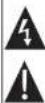
The lighting flash with arrowhead symbol within an equilateral triangle, is intended to show the use in the presence of untreated 'drought-cement collapse' within the product's enclosure that may be at natural magnitude in condition a risk of electric to persons.
The examination is within an equivalent range is intended to select the user in the presence of important operating and maintenance (serving) institutions in the literature accompanying the appliance.
CAUTION:
These servicing instructions are for use by qualified service personnel only. To reduce the risk of electric shock, do not perform any servicing other than that contained in the operating instructions unless you are qualified to do so. Refer to manual for servicing instructions.
POWER SUPPLY:
Connect one end of the supplied power cable to the AC jack on the back of the unit and other end in an AC100-21CV and outlet. If you have difficulty inserting the plug, turn I now and reinsect it, if the unit will not be used for a long time, disconnect the plug from the outlet.
POWER MANAGEMENT:
- If the prayer will not be used for a period of time, please disconnect the power.
- Before plugging the power cord into an AC outlet, make sure that all the connections have been made.
Precautions
FCC Statement
This device complies with Part 15 of the FOG Rules. Operation is subject to the following two conditions:
[1] This device may not cause harmful interference, and
[2] This device must accept any Inheritance received, including Interference that may cause undestad operation.
Note:
This equipment has been tested and found to comply with the limits for Grass B digital access, pursuant to Part 15 of the FCC risks. These limits are designed to provide reasonable protection against harmful interference in a residential installation. This equipment generates uses and can Romania radio frequency energy and, if not reliable and used in accordance with the instructions, may cause harmful interference to radio communications. However, there is no guarantees that interference will occur in a particular instance. If this equipment causes harmful interference to reduce or television reception, which can be determined by turning the equipment off and on. The user is
encouraged to try to correct the interference by one or more of the following measures: Record or relocate the receiving system
- Increase the separation between the equipment and receiver.
Connect the equipment into an outlet on a circuit different from that to which the receiver is connected.
Consult the dealer at an experienced media TV insurance for help
Use of shielded cable is required to comply with Case B limits in Support B of Part 15 of the FCC rules.
Do not make any changes or modifications to the equipment unless otherwise specified in the manual. If such changes or modifications should be made, you could be required to stop operation of the equipment.
NOTE:
The LCD panel used in this television contains millions of thin film translators that have been manufactured using a high technology process to deliver a crisp, clear, and detailed picture. Occasionally, a few of these translators may become static or non-active, please note that this does not affect the performance of the television.
Copyright Protection
Unauthorised copying, broadening, public performance, and lending of disks are prohibited. This product incorporates copyright protection technology that is protected by method claims of certain U.S. patents and other intellectual property rights owned by Macrovision Corporation and other rights owners. Use of this copyright protection technology must be authorised by Macrovision Corporation, and is intended for home and other limited viewing uses only unless otherwise authorized by Macrovision Corporation. Reverse engineering or disassembly is prohibited.
Important Safety Instructions
-
Head instructions: At the safety and operating instructions should be read before the product or approved
-
Maintain instructions. The safety and operating instructions should be retained for future reference.
-
Need Warnings: All warnings on the product and in the operating instructions should be adhered to.
-
Follow instructions: All operating and usage instructions should be followed.
-
Cleaning: Unplug this product from the wall outlet before cleaning. Do not use liquid cleaners or sensor cleaners. Use a deep cloth for cleaning.
-
Attachments: Use only attachments recommended by the manufacturer. Use of other attachments may be hazardous.
-
Water are Moulure: Do not use this product near water (e.g., near a bath lub, washbowl, kitchen sink, laundry lub, in wet basements, or near a swimming pool and the like).
-
Accessories: Do not place this product on an unstable cart, stand, tin pod, bracket, or table. Use only with carts, stands, tr pods, brackets, or taccles recommended by the manufacturer or said with the product. Any mounting of the product should follow the manufacturer's instructions and should use a mounting accessory recommended by the manufacturer.
-
A product and net combination should be moved with one. Quick stops, excessive force, and uneven surfaces may cause the product and net combination to overturn.
-
Ventilation: Stor and openings in the cabinet are provided for ventilation to ensure reliable operation of the product and to protect if from downloading. These openings should never be blocked by placing the product on a bed, rails, rug, or other similar surface. The product should not be placed in a built-in installation such as a bookcase or rack unless proper ventilation is provided in the manual and instructions have been adhered to
-
Power Sources: This product should be operated only from the type of power source indicated on the filing label if you are not sure of the type of power supply to your home, consult your product dealer or local power company. For products intended to operate from battery power or other sources, refer to the operating instructions.
-
Grounding or Polarization. This product may be equipped with a polized alternating-current line plug that has one blade wider than the other. This plug will only sit into the power outlet in one direction. This is a safety feature. If you are unable to insert the plug fully into the outlet, try reversing the direction of the plug. If the plug should still fall to it, contact an electrician to replace the obsolete outlet. Do not defeat the safety purpose of the polarized plug.
-
Power Cord Protection: Power supply cords should be routed so that they are not likely to be walked on or pinched by items placed upon or against them, paying particular attention to cords at plugs, convenience neaparticles, and at the point which they exit from the product.
-
Protective Attachment Plug. The product may be equipped with an attachment plug with overhead protection. This is a safety feature. See the operating instructions for replacement or directions to reset the protective device. If replacement of the plug is required, be sure the service technician has used a replacement plug that has the same owned protection so the original plug as speared by the manufacturer.

Important Safety Instructions
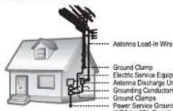
- Outdoor Antenna Grinding: If an outside antenna is connected to the product, be sure the antenna system is grounded so as to provide some protection against voltage surge and built-up static charges. Article 810 of the National Fabrical Code, ANS/NPPA 70 previous information with regard to proper grounding of the mask and supporting structures, grounding of the lead-in wire to an antenna-discharge unit, sides of grounding conductors, location of antenna-discharge unit, nonmedium in grounding electrodes, and requirements for the grounding electrode (see Figure).
-
Lightning: For added protection for this product, unplug it from the wall auditor and disconnect the elements or codes system during a lightning storm or when it is left unattended and unused for long periods of time. This will prevent damage to the product due to lightning or power-line surgeons.
-
Power Lines: An outside antenna system should not be located in the vicinity of newhead power lines or other electric light or power circuits, or where it can fall into such power lines or circuits. When installing an outside antenna system, antenna cars should be taken to keep from touching such power lines or circuits, so contact with them might be fast.
-
Overloading: Do not overload wall outlets, extension costs, or integral convenience receptacle as live can result in a risk of fire or electric shock.
-
Object and Liquid Entry: Never push objects of any kind into this product through openings as they may touch dangerous voltage paints or small-out parts for could result in a true or electric shock. Never soliquid of any kind on the product.
-
Servicing: Do not attempt to service this product yourself as opening or removing covers may expose you to dangerous voltage or other hazards. Refer all servicing to qualified service personnel.
-
Damage Recurring Service: Unplug this product from the wall outlet and never servicing to qualified service personnel under the following conditions: a) when the power supply or plug is damaged; b) if liquid has been spliced or it objects have fallen into the product; c) if the product has been exposed to rain or water; d) if the product draws or operates normally by following the operating instructors. Adjust only those controls that are covered by the operating instructions, which is impeded, adjusted for other control methods, result in damage and all other requirements; e) if liquid is possible then removed to the product be to normal operation; f) if the product has been dropped or damaged in any way; g) when the product exhibits a different change in performance—this indicates a need for service.
Important Safety Instructions
- Replacement Parts: When replacement parts are required, be sure that your service technician has used replacement parts specified by the manufacturer or have the same characteristics as the original part. Unauthorized substitutions may result in re, electric shock, or other hazards.
- Safety Check: Upon composition of any service or repairs to this product, ask the service technology in conform safety clarity to ensure that the product is in proper marketing solution.
- Wall or Ceiling Mounting: The product should be mounted to a wall or ceiling only as recommended by the manufacturer
- Heat: The product should be situated away from heat sources such as radiators, heat registers, steves, or other products (including ampiliaries) that produce heat.
Package Contents
Please make sure the following items are included with your LCD TV-monitor. If any items are missing, contact your dealer
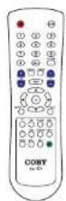
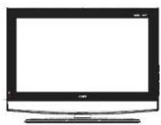
LCD Television
Remote Control
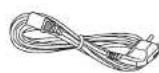
Power Cord
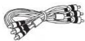
AV Cable
Unit View
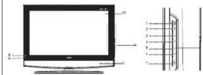
1. MODE-ENTER
Press to shift modes. While working with the
men, presex to confirm sellings
- PENO
1032 to display are system here.
Press to skip channels forward
It also works as the up direction button while
wording with the meet,
Erste in skin channel backward.
It also works as the down direction button
while working with the menu.
5.VOL
Press to increase the volume.
• All marks as the 24th place of time while finding with the more
while coming with the more.
Press to decrease the volume.
I also works so the all-direction in line
while working with the menu.
Unit View
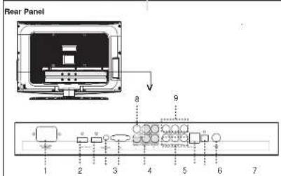
1.
Connect with the power supply
- HOME
Input the audio/video signal.
3 HDMI
legal the audio/video signal
- FC Audio In
Input the PC audio signal.
5.004
Connect with the VGA port on the computer.
- Component Input
YCb/Pb Cr/Pr -- Input the video signal
AUDIO L AUDIO R Input the audio signal
- AVI Inou
VIDEO-1 -- Input the voice signal.
AUDIO: AUDIO-B. Next the audio signal
B. 6123 Ulvis Jns.
VIDEO: 2.145-1000
3. AV Output
VIDEO-OUT - - culpr the video signal
A###, A###R - Output the audio
cigral.
- S-VIDEO
Input for S-V input signal
11.OFTICAL
Cloud the audio signal
- Запрям, Ice
Connect with the TV RF signal source
0 11
2
Remote Control
Remote Control
Remove the battery compartment cover located on the rear of the remote control. Insert 2 x "AM" battery, making sure to match their polarity [1-1] to the markings on the inside of the compartment replace the cover.
Batteries in the remote will last for approximately 6 months under normal use. Replace the batteries in the remote control does not work. Do not mix old with new batteries, or different types of batteries.
Remove the batteries from the remote if it will not be used for a long period of time.
Warnings:
The battery used in this device may present a file or chemical cure if mislocated. Do not recharge, therefore, or need the battery (21:55)
Keep followers away from chicken
Using the Hemole Control
To use the remote point it at the remote server of the player. Operate the remote within 20 feet of the sensor and at an angle of ≤slant 30 degrees.
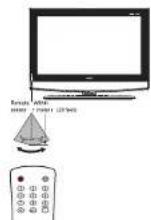
The operating distance may vary depending on the brightness around.
Notes:
Do rel point bright light directly at the remote central source.
Do not state objects between the remote control unit and the remote control sensor.
Do not use this remote control unit while simultaneously operating the remote control unit of any other equipment.
Remote Control
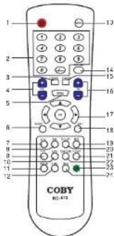
Remote Control Drawing
- POWER button
Press to turn the power on/off
- Numone Koppad
Press to input data.
3.5M508
Press to select the audio mode.
- VOLUME 7 BUTTON
Press to squ
- MENO 5.609
Press to show the system menu.
a. sleep lion
17820 12 36506 118 3994 11:30
7、十八节 5.6.69
Please be step the following entries to mark:
Davon to far
Please be aware, the bests are well-fitted.
- PAG - 100%
Press to skip the favorite channel is backward
- EPG Smith
Access the Electronic Program Guide.
11 SCALE FURGER
Adjust the display effect
12 STILL SLOO
Press to freeze the picture.
- MODE b.i.p.
Press to select the working mode.
- RETURN button
Press to return to the previously aware channel
- P.Moce
Select the picture mode.
- CHANNEL
Press to chip channels
- Direction & OK
While working with the system menu, press the direction buttons to
move the cursor and press OK to confirm settings.
- EXIT button
Press to exit the system menu.
- M18 50min
Set the ATV audio mode or the CTV audio language.
20.CH LIST
Press to display the channel list
- V-CHIP
Access the LOCK menu.
- CAPTION
Select the closed option made (OG Off, GG On, OG On More)
- MUTE bode
Press to mufflelease sound.
M. INFO
Press to show the current working information.
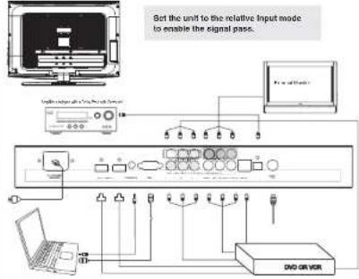
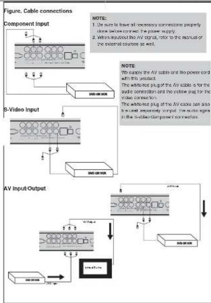
Cable Connections
Figure. Cable connections
flowchart
graph TD
    A["Computer"] --> B["Input Module 1"]
    B --> C["Main Unit 1"]
    C --> D["Device 1"]
    C --> E["Device 2"]
    C --> F["Device 3"]
    C --> G["Device 4"]
    C --> H["Device 5"]
    C --> I["Device 6"]
    C --> J["Device 7"]
    C --> K["Device 8"]
    C --> L["Device 9"]
    C --> M["Device 10"]
    C --> N["Device 11"]
    C --> O["Device 12"]
    C --> P["Device 13"]
    C --> Q["Device 14"]
    C --> R["Device 15"]
    C --> S["Device 16"]
    C --> T["Device 17"]
    C --> U["Device 18"]
    C --> V["Device 19"]
    C --> W["Device 20"]
    C --> X["Device 21"]
    C --> Y["Device 22"]
    C --> Z["Device 23"]
    C --> AA["Device 24"]
    C --> AB["Device 25"]
    C --> AC["Device 26"]
    C --> AD["Device 27"]
    C --> AE["Device 28"]
    C --> AF["Device 29"]
    C --> AG["Device 30"]
    C --> AH["Device 31"]
    C --> AI["Device 32"]
    C --> AJ["Device 33"]
    C --> AK["Device 34"]
    C --> AL["Device 35"]
    C --> AM["Device 36"]
    C --> AN["Device 37"]
    C --> AO["Device 38"]
    C --> AP["Device 39"]
    C --> AQ["Device 40"]
    C --> AR["Device 41"]
    C --> AS["Device 42"]
    C --> AT["Device 43"]
    C --> AU["Device 44"]
    C --> AV["Device 45"]
    C --> AW["Device 46"]
    C --> AX["Device 47"]
    C --> AY["Device 48"]
    C --> AZ["Device 49"]
    C --> BA["Device 50"]
Antenna-Power Connection
- Connect TV RF sources to the antenna port. TV RF signals include: receiving antenna/SATV net. You can use 75 Ohm coaxial cable to connect outdoor antennas.
- Insert one and of the suparied power cord to the prayer's power jack and the other end to the 110-240V AC wall outlet.
Component Input (Y ChPb CrPr)
The component port is capable of accepting high-determination signals from standard video sources (e.g., cable-satellite boxes, DVD players, VDRs, etc.) 1. Connect the VIPoPr port by the component cable (not supplied) to input the video signal. 2. Connect AUDIO- "AUDIO-R" port by the supply AV cable to input the audio signal. The net and the white plug at the AV cable is for the audio connection and the yellow plug for voice connection.
Cable Connections
Figure. Cable connections
B-Video Input
The 8 Video port is capable of accepting signals from standard video sources (e.g. cable/satellite boxes, DVD players, VCHs, etc.) 1. Connect the 8-Video port by the 8-Video cable (not supplied) to input the video signal. 2. Connect the AUDIO-LIR port by the supply AW cable to input the audio signal.
AV Input-Output
The CVBS part is capable of accepting signals from standard video sources (e.g., cable/satellite boxes, DVD players, VCRs, etc.) AV Input - 1. Connect the VIDEO-1/2 port by the supplied AV cable to input the video signal. 2. Connect the AUDIO-LR port by the supplied AV cable to input the audio signal. AV Output - 1. Connect the VIDEO-CUT port by the supplied AV cable to output the video signal. 2. Connect the AUDIO-LR port by the supplied AV cable to output the audio signal.
OPTICAL Output - Digital Audio Output Connector
When MPEG data or DIY Digital audio is played, DIY Digital blotstream or MPEG audio interviews is sent to the player at a digital audio output connector. When the player is connected to a DIY or MPEG audio decoder via this output encoder, you can enjoy flower-quality audio in your home. An optical audio audio is required when a DIY digital decoder or MPEG audio decoder is used. For your reference: Dolby Digital is a digital sound compressor on Inzhinevare developed by the Dolly Laseroperator Licensing Comparison. Supporting 5.1-channel surround sound, as well as science (2-chamber) source, that techniques are larger quantities of sound radio to be efficiently awarded an audio. Conclusion for the optical digital audio output connectors: [Do not connect an amplifier] with an posted digital input connector, which does not contain the Dolly Digital or MPEG audio discriminator.
VGA Input
The VGA port of the TV is capable of accepting high-definition signals from computers with a VGA output jack. When used as a computer monitor, connect the VGA jack and the PC Audio In jack. A 10 Ph O Sub cable (not supplied) is required for VGA connection and a 30mm stereo audio cable (not supplied) is required for the audio connection.
HDMI 1:2 Input
HDMI (High Connection Multimedia Interface) is a new type of connection that intramits digital audio and video signals simultaneously over a single cable.
A HDMI cable(not applied) is required for the HDMI connection.
These HDMI input connectors are capable of receiving video resolutions up to 1080p (1080-progressive).
TV Function
TV Function
Preparations
Correa the cables [Rule to the Cable Connections section for details]
-
Press the POWER button to turn on the player.
-
Press the MODE button to select the TV signal mode.
-
Press the GH-buts to skip channels.
TV Setup Menu
Various features can be preset through the TV setup menu. TV setup menu consists of PICTURE.
AUDIO, TIME, SETUP. LOCK as well as CHANNEL. Press MENU to display the setup menu, press be left-right direction button to select the desired submenu press OK to enter
After working with the menu,
-
Press the up-down closure button to select
-
Press the left/right ejection button to adjust.
-
Press MENU to exit return to the previous menu
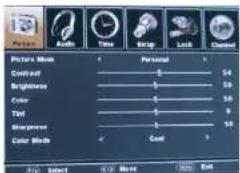
Picture Menu
| ITEM | DESCRIPTION |
| Picture Mouse | Select the picture mode (Personal, Standard, Dynamic, Self). |
| Contrast | Adjust the display contrast. |
| Brightness | Adjust the brightness to brightness |
| Color | Adjust the color color. |
| Tint | Adjust the color tint. |
| Shortness | Adjust the large shortness. |
| Color Mode | Set the color mode (Normal, White, Grey). |
TV Function
Audio Menu
| ITEM | DESCRIPTION |
| Sound Mode Set the sound mode, (Standard, None, None, Personal) | |
| Face Actual Release | |
| Trace Adjust the info. | |
| Balance Adjust the sound balance | |
| MTS Set the kTS audio for the ATV mode.(Micro, Basic, SAP) | |
| Audio Language Set the audio language (English, French, Scottish) | |
Time Menu
| ITEM | DESCRIPTION |
| Sleep Time | The rest will take down automatically on the Sleep Time. |
| The available option to 5-10-100-40-00-90-100-100-24-0 min. Off. | |
| The count down was not immediately active, sitting. | |
| You can never have a function by repeatedly pressing the SLFP button on the phone clock. To check the timer left, press the SLFP button on the phone clock. Then read the clock time, set the timer off. | |
| Time Zone | Set the DTV time zone. |
| (Pacific Alaska) | Rocky Eastern Central Alaska |
| Daylight Swing | Set the DTV swing using function center. |
| Time | Set the DTV clock information. |
| Clock | 3 clock the DTV clock information. |
Setup Menu
| ITEM | DESCRIPTION |
| Kone Language | Set the more language |
| Transcripts | Set the programming script. |
| Zoom Code | Set the screen effect, (43, Zoom, Cinema, Real Mail, 165) |
| Noise Reduction | Adjusted the screen to its appearance. [Wak, Moka, Sheng, On] |
| Open Clickout | Press the right direction from to access the closest clickout menu. |
| QQ Code | Set the CC mode, (Left, On, CC, On Mode) |
| Sable Sided | Set the back CC mode, (001-4, Not 1-4) |
| Automated Tabler | Set the auto set CC type for OTV. (Service 1-8) |
| Option - Plus | Set the right direction factor to enter the option menu. |
| CC type on | Under the option menu, set blocks as Custom to exit the OTV. |
| On or | On or living |
| D.O. | Set D.O. pool |
| Please state it | Set the proper in the facility slot. |
TV Function
Lock Menu
| ITEM | DESCRIPTION |
| 1. | Enter Password: You are required to enter the old password to access the Lock menu. The old password is 2000. |
| 2. | Change Password: You are required to change the password, but the old password will put the new password before you again. Please remember the password since the player's reset fund on could not check the password. |
| 3. | System Loss: Set the system lock function on to access the central control setup. |
| 4. | Set the lock function on to access the central control setup. |
| 5. | USB Setup the General control. |
| 6. | TV70 Rating: Y, VT, P, FG, 14, MA. Press the command to obtain a more open button option, press OK to set back. To receive access OK closed. |
| 7. | IFNRA/Bone Rating: PG, F, R, M, NT, X, V, G, P, S. |
| 8. | Device with waiting instructions to load the mode setting. |
| 9. | Controls Setup: Console powered control. |
| 10. | Console English: G, PG, 14, BB, E, C, CBs. Console French: C, G, France, Canada, France, USA. |
| 11. | FFT Setting: Set floating right side. |
| 12. | Reset FFT: Reset FFT to be fixed. |
TV Function
Channel Menu
| TRV | DESCRIPTION |
| ApoCable Setup | Set the minimum type and aon Cable. |
| Note Scan: Search channels of universal body. Press the right direction button to start forward, press MUNU in select. When use Cable system, you need to be set the one's system before start out again start. The available options: MUTO, STD, RCI HRC. | |
| Favorite: Make the favorite channel solution. Press the right direction button to access the the. Favorite. List. Press the updoin in disorder button to select the checked channel. Press OK to collect the favorite channel. Re release, access OK right. Press the following button to lamp pages in the ShowPlace list. | |
| Show Date: Use the following table. Press the right direction button to access the Show Date. List. Press the updoin in order button to select the channel, press OK to include the channel, press OK again to release. Press the following button to turn pages in the ShowPlace list. | |
| Classed No | Press the right direction button to select the channel. |
| Channel Label | List for channels' label. |
| 1. Select "Classed No", press the leading direction button to select the channel. | |
| 2. Select "Channel Label", press the right direction button to show the old menu for the menu, press the leading direction button to serve leading. Press the leading direction button to select. | |
AV Function
AV Function
The player's AV function consists of the AV IN function and the AV OUT function. You can not call enjoy programs from external input sources through the AV IN function but can also transmit the player's signal to the external monitor using the AV OUT function.
-
Connect the external AV signal source or monitor. Refer to the "Cable Connection" section for details
-
Press the MODE button to select the relevant mode (AV1, AV2, S Video, Component, HDMI, HDMI2)
NOTE: The AV OUT function is any available for the AV1. AV2. 8-V video mode.
AV Setup Menu
Various features can be present through the AV menu.
Press the MEND SCHOI is displayed for AV here.
AV setup menu consists of PICTURE, AUDIO, TIME, SETUP as well as LOCK. Press the left-right direction button to select the desired sub-menu, press OK to enter. The LOCK setup menu is any available for the AV1. AV2 and 5-Video mode
While working with the menu
-
Press the up/down direction buttons to select the desired item.
-
Press the left-right direction button to adjust.
-
Press MENU to export to the previous menu
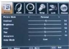
NOTE: Please see the TV section for the menu descriptions
PC Function
PC Function
You can use the unit's TFT LCD as your computer's monitor.
- Shut down both the unit and the computer. Connect the VGA jack and PC Audio in jack. See the
"Cable Connection section.
- Turn on the units and the computer. Press the MODE button to select VGA.
PC Setup Menu
Focus features can be opened through the PG menu.
Press the MENU button to display the PG menu.
PC setup menu consists of PICTURE, AUDIO, TIME, as well as SETUP.
Press the left-right direction is then to select the desired submen, press OK to enter
While working with the menu
-
Press the option direction influences to select the desired items
-
Press the left-right direction button to adjust
-
Press MENU to extretum to the previous menu
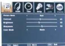
NOTE: Please see the TV section for the menu descriptions
Adjust the PC Screen
Upon switching to the PC mode, the member will be automatically regulated for a proper functioning. If the result is not up to your expectation, please perform the following steps to adjust the screen manually.
-
Enter the "Advanced" sub-menu from the SETUP menu. Select "Auto" and press the all-right direction button to adjust the monitor automatically.
-
Or if you still have problem with the monitor after, adjust "H-Pos", "V-Pos", "Clock" as well as "Please" accordingly under the SETUP menu.
COBY®
TFT LCD Widescreen Television
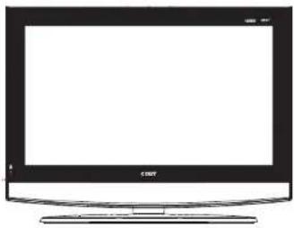
natural_image
Front view of a flat-screen television computer with blank screen (no text or symbols visible)Instruction Manual
Model No : TF-TV 2617
TF-TV 3217
TF-TV 3717
TF-TV 4217
Please read this manual before connection and use.
Main Features
This product incorporates the LCD display and the TV receiver in one system.
Multiple Mode
TV (ATV, □TV)
247
- VIDEO
COMPONENT
HOMI
HDM2
AGA
High Quality Properly
High Revolution
Adapt an MPEG2 decoding format to achieve horizontal resolution more than 500 lines.
Supropor wound
Built-in Darby Digital decoder to output high quality sound effects
Screen
Support the picture size of a normal screen (1:3) and a wide screen (18:0)
LCD (Liquid Crystal Display)
Designed with color TFT liquid crystal display usually shows the data
NOTE: It is normal for a TFT screen to experience some light or dark spots appearing on the LCD screen.
Specifications
| TF-TV 2017 | ||
| TFT Panel characteristic | Active Area | 575/264(±320/182X/mm) (25" Degrad) |
| Resolution | 1380/260 | |
| Display Color 16.90 | ||
| Peak Filter 3.405(Hx0.4215V)/mm | ||
| TV Characteristic | TV system | NTSC, ATSC |
| Tuning system | FS with PLL | |
| Antenna resistance | 75 Ω/Ω/kHz | |
| Standard | Power consumption | On working 110.0" (Max)Standing <2WSpeaker 2x (5.2", 10W) |
| Operating temperature range | 10-40°C | |
| Dimension | 26.1" X 5.2" X 15.7" | |
| TF-TV 3217 | ||
| TFT Panel characteristic | Active Area | 697/685(±200/256)(Max)(31.5" Diagonal) |
| Resolution | 1380/264 | |
| Display Color 16.90 | ||
| Peak Filter 170.251(±510.750") | m μ | |
| TV Characteristic | TV system | NTSC, ATSC |
| Tuning system | FS with PLL | |
| Antenna resistance | 75 Ω/Ω/kHz | |
| Standard | Power consumption | On working 180.0" (Max)Standing <2WSpeaker 2x (5.2", 10W) |
| Operating temperature range | 10-40°C | |
| Dimension | 31.5" X 5.2" X 22.9" | |
Specifications
| TF-TV 3717 | ||
| ITT Panel characteristic | Action Area | 450.4(###)51.2(###/20.6" Diagnosis) |
| Resolution | 1920x1000 | |
| Drugsize Coir R.L/N | ||
| Panel Film C:1420M (X:4275V)/mm | ||
| TV Characteristic | TV system | NTSC, ATSC |
| Tuning system | FS with PLL | |
| Antenna impedance | 75Ω x 100Ω | |
| Standard | Power consumption | On working 250 kJ(Max)Standing <2WSpeaker 2x(8Ω 10W)+2x(8Ω 10W) |
| Operating temperature range | 10°C-40° | |
| Dimension | 35.6 X 13.0' X 26.6' | |
| TF-TV 4217 | ||
| ITT Panel characteristic | Action Area | 950.4(###)55.2(###/20.6" Diagnosis) |
| Resolution | 1920x1000 | |
| Drugsize Coir R.L/N | ||
| Panel Film C:1420M (X:4275V)/mm | ||
| TV Characteristic | TV system | NTSC, ATSC |
| Tuning system | FS with PLL | |
| Antenna impedance | 73Ω x 100Ω | |
| Standard | Power consumption | On working 250 kJ(Max)Standing <2WSpeaker 2x(8Ω 10W)+2x(8Ω 10W) |
| Operating temperature range | 10°C-40° | |
| Dimension | 40.1 X 13.0' X 26.6' | |
Troubleshooting
| Symptom | Check and Action |
| No power | ● Make sure the unit has been powered on currently ● Check if the power cord has been properly connected to the power outlet ● Check if the main power cord has been connected on |
| No picture | ● Try another TV channel ● Check if the system carried on the proper and secure ● Check if the connection cables are damaged |
| No sound | ● Increase the volume ● Check if the NUTE fund on the arc has been installed ● Check if the sound system has been properly rated ● Check if the AV audio signal input cables has been connected property |
| Color choices | ● Reset the one or system of the unit ● Check if the system has been properly connected ● Check if the AV audio signal input cables is connected property |
| Picture and sound are improved | ● Check if the system has been properly connected - If using articles, adjusted the information. |
| Remote control does followed | ● Make sure the PUEUP circuit on the arc has been turned on currently ● Remove the obbedze solution the remote control and the player ● Point the remote control switches the remote control or the player ● Check if the batteries of the remote control have been loaded with correct colorless. ● Reduce the colorless of the remote control. |
| Message | ● Show the point checking a malfunction, starting the player for 30 m notes, after that power of the player and the remote function should reset the player. |
Cable Connections
flowchart
graph TD
    A["Component Input"] --> B["S-Video Input"]
    B --> C["AV Input-Output"]
    C --> D["AV Signal Output"]
    style A fill:#f9f,stroke:#333
    style B fill:#ccf,stroke:#333
    style C fill:#cfc,stroke:#333
    style D fill:#fcc,stroke:#333
Table of Contents
Table Of Contents
Preschools
Important Safety Instructions
Package Contents 1
Main Feature 2
10. 2. 3
Home Comp 5
BASIL O/H DETAILS 7-5
1. 10:34
19. 20. 21. 22. 23. 24. 25. 26. 27. 28. 29. 30. 31. 32. 33. 34. 35. 36. 37. 38. 39. 40. 41. 42. 43. 44. 45. 46. 47. 48. 49. 50. 51. 52. 53. 54. 55. 56. 57. 58. 59. 60. 61. 62. 63. 64. 65. 66. 67. 68. 69. 70. 71. 72. 73. 74. 75. 76. 77. 78. 79. 80. 81. 82. 83. 84. 85. 86. 87. 88. 89. 90. 91. 92. 93. 94. 95. 96. 97. 98. 99.
15.47
Troubleshooting

- CAUTION:
- POWER SUPPLY:
- POWER MANAGEMENT:
- Precautions
- FCC Statement
- Note:
- Copyright Protection
- Important Safety Instructions
- Package Contents
- Unit View
- MODE-ENTER
- 1.
- AV Output
- Remote Control
- Warnings:
- Using the Hemole Control
- Notes:
- Remote Control Drawing
- Cable Connections
- Antenna-Power Connection
- Component Input (Y ChPb CrPr)
- Figure. Cable connections
- B-Video Input
- AV Input-Output
- OPTICAL Output - Digital Audio Output Connector
- VGA Input
- HDMI 1:2 Input
- TV Function
- Preparations
- TV Setup Menu
- After working with the menu,
- AV Function
- AV Setup Menu
- While working with the menu
- PC Function
- PC Setup Menu
- Adjust the PC Screen
- Main Features
- Troubleshooting
- Table of Contents
Brand : COBY
Model : TF-TV2617
Category : Television