
ASG-GFK - Paint gun Ozito - Free user manual and instructions
Find the device manual for free ASG-GFK Ozito in PDF.


| Product Type | Paint Gun |
| Brand | Ozito |
| Model | ASG-GFK |
| Power Source | Pneumatic (air compressor required) |
| Operating Pressure | 30-50 PSI |
| Nozzle Size | 1.4 mm |
| Paint Cup Capacity | 600 ml (approx.) |
| Fluid Output | Adjustable |
| Spray Pattern | Adjustable (round, horizontal, vertical) |
| Material | Aluminum body |
| Weight | 1.2 kg (approx.) |
| Dimensions (L x W x H) | 200 x 150 x 300 mm (approx.) |
| Included Accessories | Paint gun, cup, cleaning brush, wrench |
| Recommended Paint Types | Water-based, latex, oil-based (thinned as needed) |
| Cleaning | Clean after each use with appropriate solvent |
| Safety | Wear mask, goggles; work in ventilated area |
Frequently Asked Questions - ASG-GFK Ozito
User questions about ASG-GFK Ozito
0 question about this device. Answer the ones you know or ask your own.
Ask a new question about this device
Download the instructions for your Paint gun in PDF format for free! Find your manual ASG-GFK - Ozito and take your electronic device back in hand. On this page are published all the documents necessary for the use of your device. ASG-GFK by Ozito.
USER MANUAL ASG-GFK Ozito
Working Air Pressure: 43psi (3Bar)
Max Air Pressure: 87psi (6Bar)
Air Consumption: 141-283L/min (5-10cfm)
Nozzle Size: 01.4mm
Spray Width: 40-70mm
Flow Rate: 100-190ml/min
Feed Type: Gravity
Paint Pot Size: 600ml
Air Inlet: 1/4" BSP
ozito.com.au
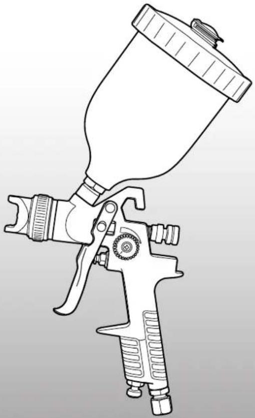
natural_image
Line drawing of a spray gun with handle and nozzle (no text or symbols)WHAT'S IN THE BOX
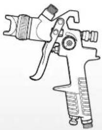
natural_image
Line drawing of a spray gun with handle and grip (no text or symbols)Spray Gun
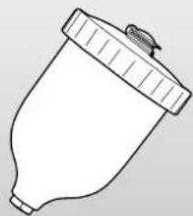
natural_image
Line drawing of a spray can with a lid and nozzle (no text or symbols)Paint Pot
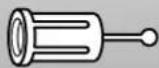
Filter
3
YEAR REPLACEMENT WARRANTY
ASG-GFK
WARRANTY
IN ORDER TO MAKE A CLAIM UNDER THIS WARRANTY YOU MUST RETURN THE PRODUCT TO YOUR NEAREST BUNNINGS WAREHOUSE WITH YOUR BUNNINGS REGISTER RECEIPT. PRIOR TO RETURNING YOUR PRODUCT FOR WARRANTY PLEASE TELEPHONE OUR CUSTOMER SERVICE HELPLINE:
Australia 1800 069 486
New Zealand 0508 069 486
TO ENSURE A SPEEDY RESPONSE PLEASE HAVE THE MODEL NUMBER AND DATE OF PURCHASE AVAILABLE. A CUSTOMER SERVICE REPRESENTATIVE WILL TAKE YOUR CALL AND ANSWER ANY QUESTIONS YOU MAY HAVE RELATING TO THE WARRANTY POLICY OR PROCEDURE.
The benefits provided under this warranty are in addition to other rights and remedies which are available to you at law.
Our goods come with guarantees that cannot be excluded at law. You are entitled to a replacement or refund for a major failure and for compensation for any other reasonably foreseeable loss or damage. You are also entitled to have the goods repaired or replaced if the goods fail to be of acceptable quality and the failure does not amount to a major failure.
Generally you will be responsible for all costs associated with a claim under this warranty, however, where you have suffered any additional direct loss as a result of a defective product you may be able to claim such expenses by contacting our customer service helpline above.
3 YEAR REPLACEMENT WARRANTY
Your product is guaranteed for a period of 36 months from the original date of purchase and is intended for DIY (Do It Yourself) use only. If a product is defective it will be replaced in accordance with the terms of this warranty. Warranty excludes consumable parts.
WARNING
The following actions will result in the warranty being void.
- If the tool has been operated on a supply voltage other than that specified on the tool.
- If the tool shows signs of damage or defects caused by or resulting from abuse, accidents or alterations.
- Failure to perform maintenance as set out within the instruction manual.
• If the tool is disassembled or tampered with in any way.
• Professional, industrial or high frequency use.
KNOW YOUR PRODUCT
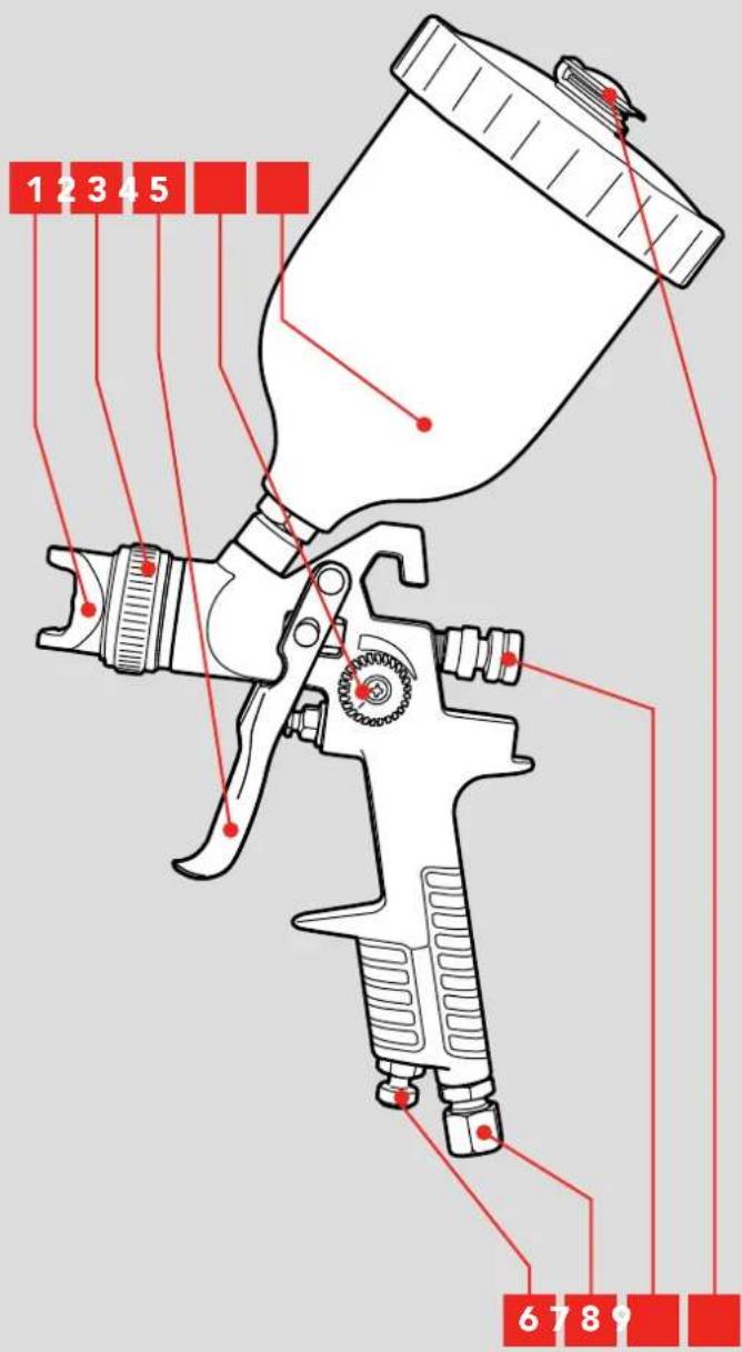
GRAVITY FEED SPRAY GUN
1 Nozzle
6 Air Regulator Valve
2 Nozzle Collar
7 Air Inlet
3 Variable Trigger
8 Fluid Adjustment Dial
4 Fan Adjustment Dial
9 Air Vent
5 Paint Pot
ONLINE MANUAL
Scan this QR Code with your mobile device to take you to the online manual.

SETUP & PREPARATION
1. ASSEMBLY

WARNING! ENSURE THE TOOL IS DISCONNECTED FROM THE AIR SUPPLY BEFORE PERFORMING ANY OF THE FOLLOWING OPERATIONS.
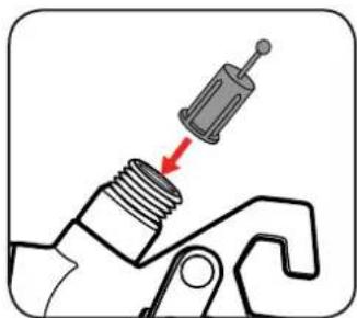
Inserting the Filter
1 Simply place the filter into the top hole of the spray gun with the knob facing up.
natural_image
Mechanical component diagram showing a threaded bolt inserted into a bracket with a red arrow indicating direction (no text or symbols)Fitting the Paint Pot
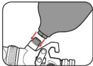
1 Align the paint pot with the hole on the top of the spray gun.
2 Screw the paint pot in tightly by hand.
natural_image
Illustration of a hand holding a tool with a bulb inserted, showing a red arrow indicating force direction (no text or symbols present)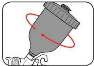
natural_image
Illustration of a spray can with red motion arrows indicating rotation (no text or symbols)Attaching to Compressor
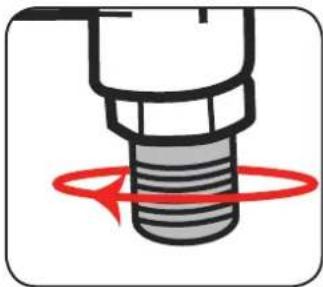
1 Wrap the threaded male air inlet of the spray gun with teflon tape in a clockwise direction.
2 Screw the female fitting clockwise onto the male end of the air inlet.
natural_image
Diagram of a mechanical component with a red circular motion indicator (no text or symbols)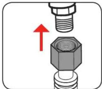
natural_image
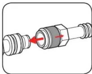
Close-up of a mechanical assembly showing a bolt inserted into a hex nut, with a red upward arrow indicating force or direction (no text or symbols)3 Pull back the sleeve on hose fitting, insert male end & release sleeve on hose fitting.
natural_image
Diagram of a mechanical connector with red arrows indicating movement or force (no text or symbols)2. PREPARATION
NOTE: FOR BEST RESULTS, SURFACE PREPARATION AND PAINT THINNING ARE THE TWO MOST IMPORTANT AREAS. ENSURE ALL SURFACES ARE FREE OF DUST, DIRT AND GREASE.
Thinning
Thinning is particularly important when spraying. Most paints are supplied ready for brush application and need to be diluted sufficiently for spraying purposes.
Follow the manufacturers guide for thinning ratios which should be labelled on the paint container.
1 Before pouring any paint or thinners work out how much of each substance is needed.
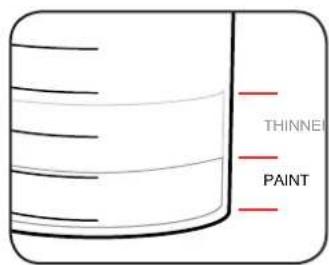
2 Pour the required paint and thinners through a filter into a mixing cup and then mix thoroughly.
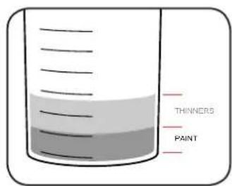
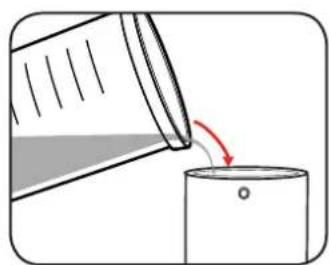
3 Once the correct viscosity is obtained, pour the mixture into the paint pot.
natural_image
Illustration of a bottle being poured into a container with a red arrow indicating the process (no text or symbols present)IMPORTANT! THE SPRAY GUN CANNOT BE USED WITH MATERIALS CONTAINING ABRASIVE SUBSTANCES, GLAZES, CAUSTIC AND ALKALINE SUBSTANCES.
3. ADJUSTING THE SPRAY GUN
Variable Trigger
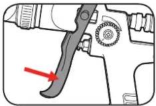
1 Squeeze the variable trigger to start spraying.
2 Release the variable trigger to stop spraying.
natural_image
Diagram of a spray gun with a lever and nozzle, showing no text or symbols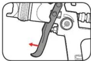
natural_image
Technical diagram of a mechanical tool with a red arrow indicating a specific component (no text or symbols present)Note: The further the variable trigger is pressed, the more fluid will flow through the gun.
Fluid Adjustment Dial
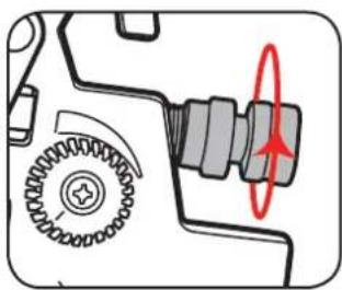
The fluid adjustment dial is a stop that limits the distance the trigger can be pressed and can therefore limit the amount of paint being sprayed.
1 Fully tighten the fluid adjustment dial.
2 Slightly loosen the fluid adjustment dial, then test setting on a scrap piece of material.
natural_image
Mechanical gear assembly diagram showing meshing gears and a highlighted shaft (no text or symbols)
natural_image
Mechanical gear assembly diagram showing meshing gears and a highlighted shaft (no text or symbols)3 Repeat step 2 until desired fluid output is reached.
Air Regulator Valve
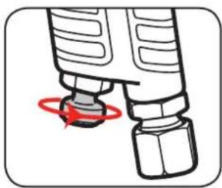
The air regulator valve controls the air pressure entering the gun.
1 To restrict the air pressure entering the spray gun turn the valve clockwise.
2 To increase air pressure entering the gun, turn the air valve anti-clockwise.
natural_image
Diagram of a mechanical component with a red circular arrow indicating rotation (no text or symbols)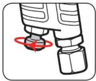
natural_image
Diagram of a mechanical component with a red circular arrow indicating rotation (no text or symbols)4. ADJUSTING THE SPRAY GUN CONT. 5
Fan Adjustment Dial
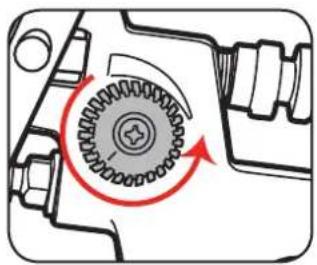
The fan adjustment dial controls the distribution of paint in the fan. Turned all the way clockwise, paint is concentrated in the centre of the fan. As the dial is turned anti-clockwise more paint is distributed toward the edges.
1 Start with the fan adjustment dial completely loosened.
2 Partly tighten the dial then test setting on a scrap piece of material.
natural_image
Mechanical gear assembly diagram showing rotational motion with no text or symbols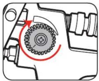
natural_image
Mechanical gear assembly diagram showing a rotating shaft and housing (no text or symbols)3 Repeat step 2 until desired fan pattern is reached.
Choosing Spray Patterns
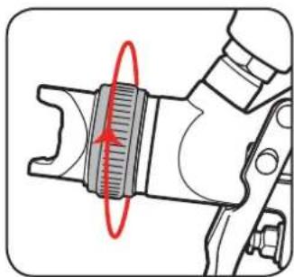
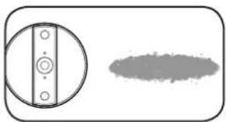
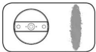
1 To change the spray pattern, loosen the nozzle collar and rotate the nozzle to the desired position. Tighten nozzle collar to secure nozzle in place.
natural_image
Mechanical component diagram showing a threaded fastener with red motion arrow (no text or symbols)For vertical surfaces:
natural_image
Simple diagram showing a circular component with four holes and a shaded oval shape (no text or symbols)For horizontal surfaces:
natural_image
Simple diagram showing a circular component with a central dot and a vertical textured shape (no text or symbols)SPRAYING TECHNIQUE
- Move the gun with the entire arm, not by flexing the wrist. This will keep the spray gun at right angles to the surface, keeping the pattern even.
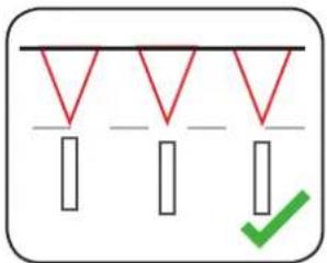
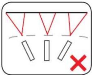
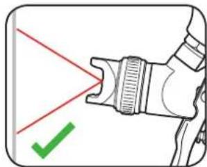
- Keep the spray gun perpendicular to the surface, so spray distance is consistent.
natural_image
Diagram of a mechanical device with red laser lines and a green checkmark (no text or symbols)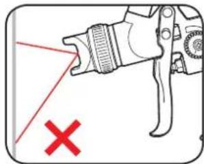
natural_image
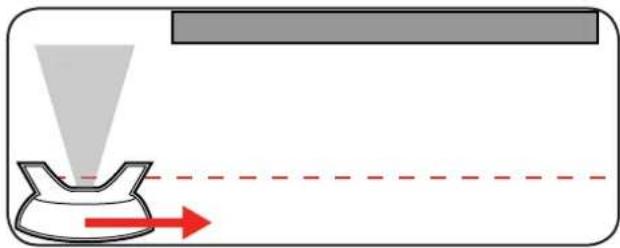
Diagram of a mechanical device with a red X mark and a red laser beam, no text or symbols present.3 Begin 15cm off the edge of the area being sprayed. Start the movement of the stroke before squeezing the trigger. Release trigger once passed the opposite edge of the workpiece.
natural_image
Diagram showing a funnel pouring liquid into a container with red arrows indicating direction (no text or symbols)Helpful Hints
- Maintain the same distance from workpiece (approx 15cm) throughout each pass.
- Maintain the same speed throughout each pass.
- Always allow a coat to completely dry before adding another coat.
- Avoid stopping and starting in the middle of workpiece as this can lead to a patchy finish.
NOTE: After each use it is essential that the spray gun is cleaned thoroughly. Failure to do so will likely cause blockages which will prevent the tool from working. FAILURE TO CLEAN THE TOOL WILL VOID THE WARRANTY.
CLEANING PROCEDURE TROUBLI
If coating material was water based (acrylic paint), use ONLY water when performing the cleaning procedure. Use of solvent based cleaning materials on water based paints will result in a new substance that will be extremely difficult to clean.
If coating material was oil based (enamel paint, lacquer etc.) use ONLY the appropriate cleaning solution. Read the cleaning instructions printed on the coating material's label to determine which cleaning material you need. The following solvent based cleaning products are safe to use in the paint sprayer:
• Diggers Easy Cleanup Turpentine Substitute (highly recommended)
- Mineral Turpentine
- Paint Thinner
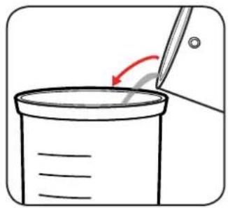
1 Empty the paint pot of remaining material.
natural_image
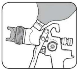
Simple line drawing of a pencil tiping a beaker with an arrow indicating rotation (no text or symbols)2 Rinse paint pot & nozzle with cleaning solution. Wipe all parts with a clean cloth.
natural_image
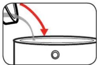
Illustration of a hand using a spray gun to handle a tool (no text or symbols visible)3 Fill paint pot with appropriate cleaning solution.
natural_image
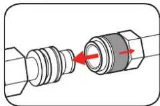
Simple line drawing of a container with liquid and a downward arrow indicating flow (no text or symbols)4 Connect the spray gun to the air supply then spray solution into a bucket.
natural_image
Diagram of a mechanical connector with red arrows indicating assembly or connection (no text or symbols)5 Repeat steps 3-4 until the cleaning solution runs clear from gun.
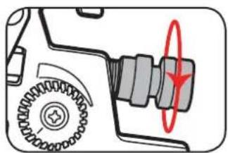
6 Unscrew and remove fluid adjustment dial, needle & spring. Clean all parts in cleaning solution.
natural_image
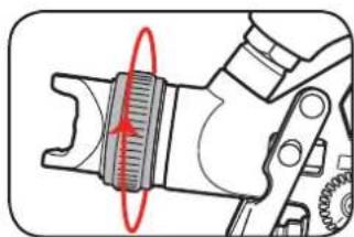
Mechanical component diagram showing gear and shaft assembly with red circular annotation (no text or symbols)7 Unscrew and remove nozzle. Clean in cleaning solution.
natural_image
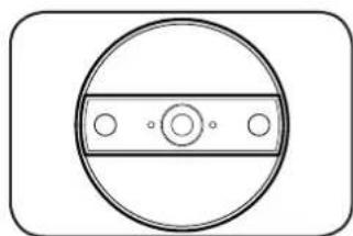
Mechanical component diagram showing a gear assembly with a red circular arrow indicating rotational motion (no text or symbols)8 Take note of the 4 holes on the nozzle, if blocked clean carefully using a small needle.
natural_image
Simple circular diagram with a horizontal bar and three small circles inside, enclosed in a rounded rectangle (no text or symbols)SHOOTING
| PROBLEM CAUSE | REMEDY | |
| Little or no material flow | Fluid adjustment dial too limited | Turn fluid adjustment dial further out clockwise |
| Air pressure too low | Increase air pressure at the compressor | |
| Turn air regulator valve further out clockwise on gun | ||
| Material too thick | Thin material | |
| Nozzle clogged | Clean nozzle | |
| Material leaking | Nozzle loose Tighten nozzle | |
| Nozzle worn | Contact Ozito for replacement spare parts | |
| Spray pattern is heavy in the middle | Fan requires adjustment | Turn fan adjustment dial further out anti-clockwise |
| Air pressure too low | Increase air pressure at the compressor | |
| Turn air regulator valve further out clockwise on gun | ||
| Spray pattern heavy at the edges | Fan requires adjustment Turn fan | adjustment dial in clockwise |
| Air pressure too high | Reduce air pressure at the compressor | |
| Turn air regulator valve further in clockwise on gun | ||
| Spray jet pulsates | Material in paint pot running out | Refill paint pot |
| Nozzle clogged Clean nozzle | ||
| Material too thick | Thin material | |
| Pattern runs or sags | Too much material is being applied | Turn fluid adjustment dial further in clockwise |
| Increase spray speed | ||
| Material is too thin | Thicken material by adding more paint | |
| Too much overspray | Gun too far from the spray surface | Reduce distance & turn fluid adjustment dial further in clockwise to reduce the amount of paint being applied. |
| Pattern is very light and splotchy | Material is too thick | Thin the material |
| Moving the spray gun to fast | Decrease spray speed |
SPARE PARTS
Nozzle
Assembly
SPASGGFK-B33A
Needle
Assembly
SPASGGFK-B11
Spare parts can be ordered from the Special Orders Desk at your local Bunnings Warehouse.
For further information, or any parts not listed here, visit www.ozito.com.au or contact Ozito Customer Service:
Australia 1800 069 486
New Zealand 0508 069 486
E-mail: enquires@ozito.com.au

GENERAL AIR TOOL SAFETY WARNINGS

WARNING! Read all safety warnings and all instructions. Failure to follow the warnings and instructions may result in electric shock, fire and/or serious injury.
Save all warnings and instructions for future reference. The term "power tool" in the
warnings refers to your mains-operated (corded) power tool or battery-operated (cordless) power tool.
- Work area safety
a. Keep work area clean and well lit. Cluttered or dark areas invite accidents.
b. Do not operate power tools in explosive atmospheres, such as in the presence of flammable
liquids, gases or dust. Power tools create sparks which may ignite the dust or fumes.
c. Keep children and bystanders away while operating a power tool. Distractions can cause you to lose control.
d. Dress properly. Do not wear loose clothing or jewellery. Keep your hair, clothing and gloves away from moving parts. Loose clothes, jewellery or long hair can be caught in moving parts.
e. Check the maximum pressure rating of any tools or accessories that you intend using with the compressor. The output pressure of the air from the compressor must be regulated so that it never exceeds the rated pressure of the tool or accessory.
f. Always wear safety goggles or glasses when using the air compressor. Never point the nozzle of an accessory towards any part of your body or towards another person.
g. Use safety equipment including safety goggles or shield, ear protection, breathing or respirator mask and protective clothing.
h. The tool must be used only for its prescribed purpose. Any use other than those mentioned in this Manual will be considered a case of misuse. The user and not the manufacturer shall be liable for any damage or injury resulting from such cases of misuse.

WARNING! In the event that an air line is cut or broken, the air supply must be turned off at the compressor. A broken air line which is not supported is extremely dangerous and can whip around very quickly, both with the capability of striking people, and blowing foreign particles into the air.
- Do not attempt to catch the air line but immediately keep bystanders well clear and turn off the air supply to the hose, turn off the compressor at the On / Off button, and then remove the hose from the compressor.
- This appliance is not intended for use by persons (including children) with reduced physical, sensory or mental capabilities, or lack of experience and knowledge, unless they have been given the supervision or instruction concerning use of the appliance by a person responsible for their safety.
• Children should be supervised to ensure that they do not play with the appliance.

SPRAY GUN SAFETY WARNINGS

WARNING!
This appliance is not intended for use by persons (including children) with reduced physical, sensory or mental capabilities, or lack of experience and knowledge, unless they have been given supervision or instruction concerning use of the appliance by a person responsible for their safety.
Using an Extension Hose
Always use an approved extension hose suitable for the air input of this tool. Before use, inspect the hose for signs of damage, wear and ageing. Replace the extension hose if damaged or defective.
When using an hose on a reel, always unwind the lead completely.
It is recommended that the hose is a maximum of 25m in length.
NEVER under any circumstances aim the nozzle at another person or animal.
• In the event of an injury occurring, seek medical advice immediately.
- The spray gun must not be used for spraying flammable paints and solvents with a flash point of less than 21^ .
• Always ensure there is adequate ventilation when spraying.
• The use of ear protection is recommended.
- Eye protection is recommended to keep hazardous vapours and liquids out of eyes.
• Always wear a face mask when spraying.
• Always read the paint manufacturers thinning instructions before using.
- Always keep the spray nozzle in place during use. Never allow the spray to come in direct contact with the skin.
- Never immerse the spray gun in liquid.
- The spray gun must not be cleaned by using flammable liquids with a flash point of less than 21^ .
NEVER spray near a naked flame, including an appliance pilot light.
NEVER smoke whilst spraying.
NEVER allow children to operate or play with the spray gun.
- Before cleaning, always disconnect the appliance from the air supply.
• Always disconnect from air supply when refilling the paint pot.
• After every use ensure you clean your spray gun thoroughly.
NEVER use the spray gun outside when it is raining.
DESCRIPTION OF SYMBOLS
 | Warning |  | Read instruction manual |
 | Wear ear protection |  | Wear eye protection and breathing mask |
| ml/min | Millilitres per minute | cfm | Cubic feet per minute |
CARING FOR THE ENVIRONMENT

Power tools that are no longer usable should not be disposed of with household waste but in an environmentally friendly way. Please recycle where facilities exist. Check with your local council authority for recycling advice.

Recycling packaging reduces the need for landfill and raw materials. Reuse of recycled material decreases pollution in the environment. Please recycle packaging where facilities exist. Check with your local council authority for recycling advice.
Ozito
TOUCH-UP GRAVITY FEED SPRAY GUN
70-110 ml/min
INSTRUCTION MANUAL
SPECIFICATIONS
Working Air Pressure: 30psi (2Bar)
Max Air Pressure: 58psi (4Bar)
Air Consumption: 28-113L/min (1-4cfm)
Nozzle Size: 0.8mm
Spray Width: 20-50mm
Flow Rate: 70-110ml/min
Feed Type: Gravity
Paint Pot Size: 100ml
Air Inlet: 1/4" BSP
ozito.com.au
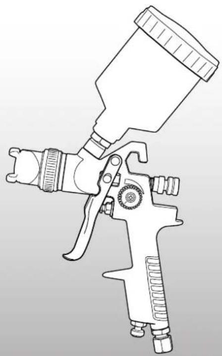
natural_image
Line drawing of a spray gun with handle and grip (no text or symbols)WHAT'S IN THE BOX
Spray Gun
Filter
3
YEAR REPLACEMENT WARRANTY
ASG-GFK
WARRANTY
IN ORDER TO MAKE A CLAIM UNDER THIS WARRANTY YOU MUST RETURN THE PRODUCT TO YOUR NEAREST BUNNINGS WAREHOUSE WITH YOUR BUNNINGS REGISTER RECEIPT. PRIOR TO RETURNING YOUR PRODUCT FOR WARRANTY PLEASE TELEPHONE OUR CUSTOMER SERVICE HELPLINE:
Australia 1800 069 486
New Zealand 0508 069 486
TO ENSURE A SPEEDY RESPONSE PLEASE HAVE THE MODEL NUMBER AND DATE OF PURCHASE AVAILABLE. A CUSTOMER SERVICE REPRESENTATIVE WILL TAKE YOUR CALL AND ANSWER ANY QUESTIONS YOU MAY HAVE RELATING TO THE WARRANTY POLICY OR PROCEDURE.
The benefits provided under this warranty are in addition to other rights and remedies which are available to you at law.
Our goods come with guarantees that cannot be excluded at law. You are entitled to a replacement or refund for a major failure and for compensation for any other reasonably foreseeable loss or damage. You are also entitled to have the goods repaired or replaced if the goods fail to be of acceptable quality and the failure does not amount to a major failure.
Generally you will be responsible for all costs associated with a claim under this warranty, however, where you have suffered any additional direct loss as a result of a defective product you may be able to claim such expenses by contacting our customer service helpline above.
3 YEAR REPLACEMENT WARRANTY
Your product is guaranteed for a period of 36 months from the original date of purchase and is intended for DIY (Do It Yourself) use only. If a product is defective it will be replaced in accordance with the terms of this warranty. Warranty excludes consumable parts.
WARNING
The following actions will result in the warranty being void.
- If the tool has been operated on a supply voltage other than that specified on the tool.
- If the tool shows signs of damage or defects caused by or resulting from abuse, accidents or alterations.
- Failure to perform maintenance as set out within the instruction manual.
• If the tool is disassembled or tampered with in any way.
• Professional, industrial or high frequency use.
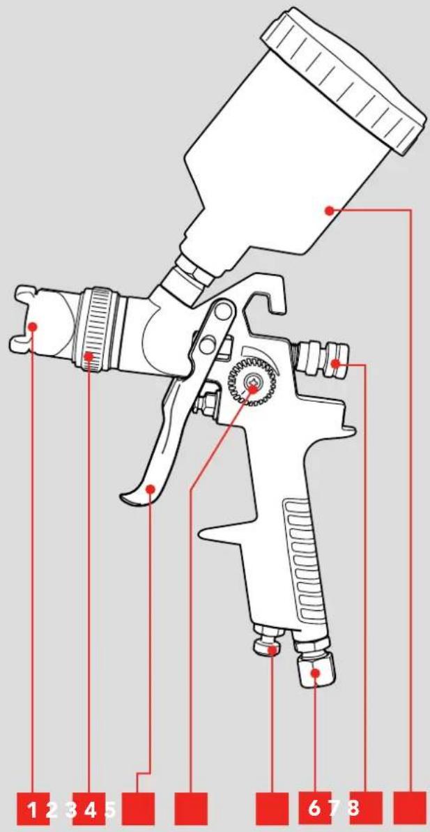
KNOW YOUR PRODUCT
GRAVITY FEED SPRAY GUN
1 Nozzle
5 Air Regulator Valve
2 Nozzle Collar
6 Air Inlet
3 Variable Trigger
7 Fluid Adjustment Dial
4 Fan Adjustment Dial
8 Paint Pot
ONLINE MANUAL
Scan this QR Code with your mobile device to take you to the online manual.

SETUP & PREPARATION
1. ASSEMBLY

WARNING! ENSURE THE TOOL IS DISCONNECTED FROM THE AIR SUPPLY BEFORE PERFORMING ANY OF THE FOLLOWING OPERATIONS.
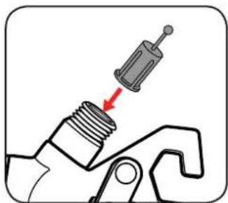
Inserting the Filter
1 Simply place the filter into the top hole of the spray gun with the knob facing up.
natural_image
Mechanical component diagram showing a threaded bolt being inserted into a spring-loaded tool (no text or symbols)Fitting the Paint Pot
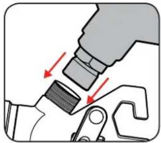
1 Align the paint pot with the hole on the top of the spray gun.
2 Screw the paint pot in tightly by hand.
natural_image
Mechanical assembly diagram showing a tool inserted into a component with red arrows indicating direction (no text or symbols present)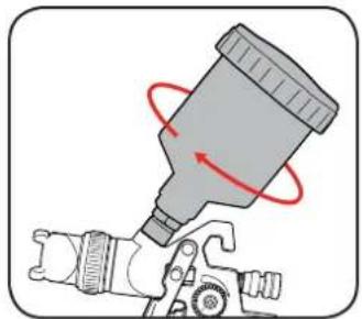
natural_image
Illustration of a spray gun with red motion arrows indicating motion (no text or symbols)Attaching to Compressor
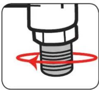
1 Wrap the threaded male air inlet of the spray gun with teflon tape in a clockwise direction.
2 Screw the female fitting clockwise onto the male end of the air inlet.
natural_image
Close-up of a mechanical component with red circular arrows indicating rotational motion (no text or symbols)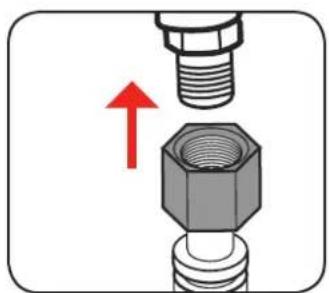
natural_image
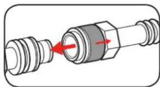
Close-up of a mechanical assembly showing a bolt inserted into a hex nut, with a red upward arrow indicating force or direction (no text or symbols)3 Pull back the sleeve on hose fitting, insert male end & release sleeve on hose fitting.
natural_image
Diagram of a mechanical connector with red arrows indicating assembly or movement (no text or symbols)2. PREPARATION
NOTE: FOR BEST RESULTS, SURFACE PREPARATION AND PAINT THINNING ARE THE TWO MOST IMPORTANT AREAS. ENSURE ALL SURFACES ARE FREE OF DUST, DIRT AND GREASE.
Thinning
Thinning is particularly important when spraying. Most paints are supplied ready for brush application and need to be diluted sufficiently for spraying purposes.
Follow the manufacturers guide for thinning ratios which should be labelled on the paint container.
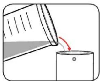
1 Before pouring any paint or thinners work out how much of each substance is needed.
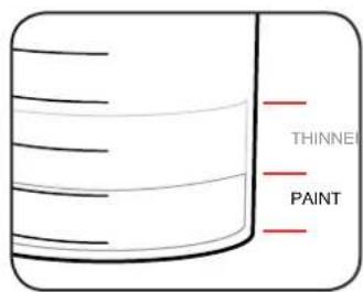
2 Pour the required paint and thinners through a filter into a mixing cup and then mix thoroughly.
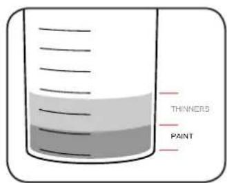
3 Once the correct viscosity is obtained, pour the mixture into the paint pot.
natural_image
Illustration of a bottle being poured into a container with a red arrow indicating the process (no text or symbols present)IMPORTANT! THE SPRAY GUN CANNOT BE USED WITH MATERIALS CONTAINING ABRASIVE SUBSTANCES, GLAZES, CAUSTIC AND ALKALINE SUBSTANCES.
3. ADJUSTING THE SPRAY GUN
Variable Trigger
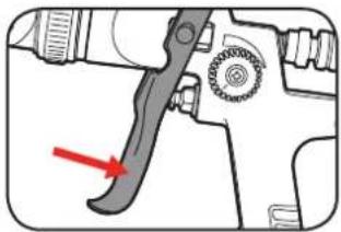
1 Squeeze the variable trigger to start spraying.
2 Release the variable trigger to stop spraying.
natural_image
Diagram of a spray gun with a lever and nozzle, showing no text or symbols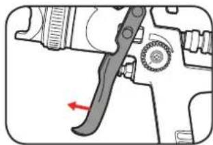
natural_image
Technical diagram of a mechanical tool with a red arrow indicating a specific component (no text or symbols present)Note: The further the variable trigger is pressed, the more fluid will flow through the gun.
Fluid Adjustment Dial
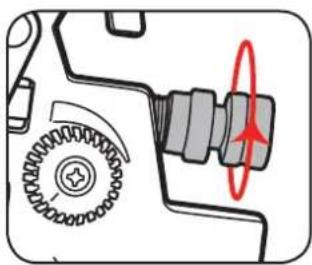
The fluid adjustment dial is a stop that limits the distance the trigger can be pressed and can therefore limit the amount of paint being sprayed.
1 Fully tighten the fluid adjustment dial.
2 Slightly loosen the fluid adjustment dial, then test setting on a scrap piece of material.
natural_image
Mechanical gear assembly diagram showing meshing gears and a highlighted shaft (no text or symbols)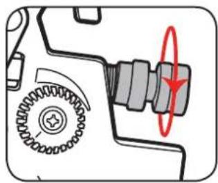
natural_image
Mechanical gear assembly diagram showing meshing gears and a highlighted shaft (no text or symbols)3 Repeat step 2 until desired fluid output is reached.
Air Regulator Valve
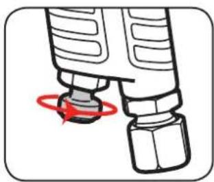
The air regulator valve controls the air pressure entering the gun.
1 To restrict the air pressure entering the spray gun turn the valve clockwise.
2 To increase air pressure entering the gun, turn the air valve anti-clockwise.
natural_image
Diagram of a mechanical component with a red circular arrow indicating rotation (no text or symbols)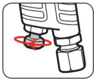
natural_image
Diagram of a mechanical component with a red circular arrow indicating rotation (no text or symbols)4. ADJUSTING THE SPRAY GUN CONT. 5
Fan Adjustment Dial
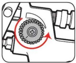
The fan adjustment dial controls the distribution of paint in the fan. Turned all the way clockwise, paint is concentrated in the centre of the fan. As the dial is turned anti-clockwise more paint is distributed toward the edges.
1 Start with the fan adjustment dial completely loosened.
2 Partly tighten the dial then test setting on a scrap piece of material.
natural_image
Mechanical gear assembly diagram showing rotational motion with no text or symbols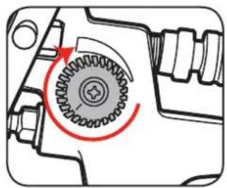
natural_image
Mechanical gear assembly diagram showing a rotating shaft and housing (no text or symbols)3 Repeat step 2 until desired fan pattern is reached.
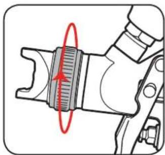
Choosing Spray Patterns
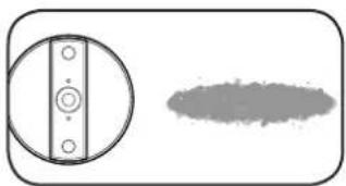
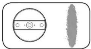
1 To change the spray pattern, loosen the nozzle collar and rotate the nozzle to the desired position. Tighten nozzle collar to secure nozzle in place.
natural_image
Mechanical component diagram showing a threaded fastener with red motion arrow (no text or symbols)For vertical surfaces:
natural_image
Simple diagram showing a circular component with four holes and a shaded oval shape (no text or symbols)For horizontal surfaces:
natural_image
Simple diagram showing a circular component with a central dot and a vertical textured shape (no text or symbols)SPRAYING TECHNIQUE
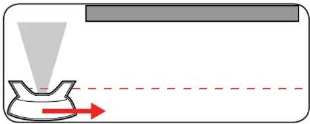
- Move the gun with the entire arm, not by flexing the wrist. This will keep the spray gun at right angles to the surface, keeping the pattern even.
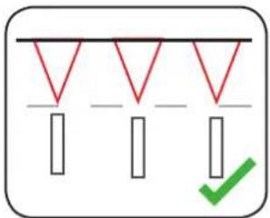
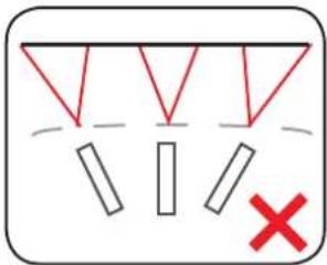
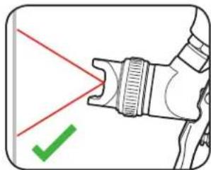
- Keep the spray gun perpendicular to the surface, so spray distance is consistent.
natural_image
Diagram of a mechanical device with red laser lines and a green checkmark (no text or symbols)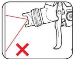
natural_image
Diagram of a mechanical device with a red X mark and a red laser beam, no text or symbols present.3 Begin 15cm off the edge of the area being sprayed. Start the movement of the stroke before squeezing the trigger. Release trigger once passed the opposite edge of the workpiece.
natural_image
Diagram showing a funnel pouring liquid into a container with red arrows indicating direction (no text or symbols)Helpful Hints
- Maintain the same distance from workpiece (approx 15cm) throughout each pass.
- Maintain the same speed throughout each pass.
- Always allow a coat to completely dry before adding another coat.
- Avoid stopping and starting in the middle of workpiece as this can lead to a patchy finish.
NOTE: After each use it is essential that the spray gun is cleaned thoroughly. Failure to do so will likely cause blockages which will prevent the tool from working. FAILURE TO CLEAN THE TOOL WILL VOID THE WARRANTY.
CLEANING PROCEDURE TROUBLI
If coating material was water based (acrylic paint), use ONLY water when performing the cleaning procedure. Use of solvent based cleaning materials on water based paints will result in a new substance that will be extremely difficult to clean.
If coating material was oil based (enamel paint, lacquer etc.) use ONLY the appropriate cleaning solution. Read the cleaning instructions printed on the coating material's label to determine which cleaning material you need. The following solvent based cleaning products are safe to use in the paint sprayer:
• Diggers Easy Cleanup Turpentine Substitute (highly recommended)
- Mineral Turpentine
- Paint Thinner
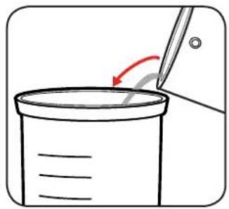
1 Empty the paint pot of remaining material.
natural_image
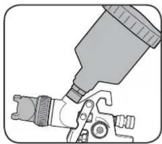
Simple line drawing of a pencil writing on a beaker with an arrow indicating motion (no text or symbols)2 Rinse paint pot & nozzle with cleaning solution. Wipe all parts with a clean cloth.
natural_image
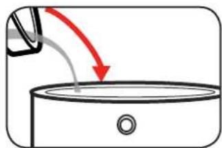
Illustration of a spray gun dispensing onto a mechanical component (no text or symbols)3 Fill paint pot with appropriate cleaning solution.
natural_image
Simple line drawing of a container with liquid and a downward arrow indicating flow (no text or symbols)4 Connect the spray gun to the air supply then spray solution into a bucket.
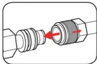
natural_image
Diagram of a mechanical connector with red arrows indicating assembly or connection (no text or symbols)5 Repeat steps 3-4 until the cleaning solution runs clear from gun.
6 Unscrew and remove fluid adjustment dial, needle & spring. Clean all parts in cleaning solution.
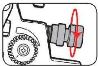
natural_image
Mechanical component diagram showing gear and shaft assembly with red circular annotation (no text or symbols)7 Unscrew and remove nozzle. Clean in cleaning solution.
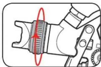
natural_image
Mechanical component diagram showing a gear assembly with a red circular arrow indicating rotational motion (no text or symbols)8 Take note of the 4 holes on the nozzle, if blocked clean carefully using a small needle.
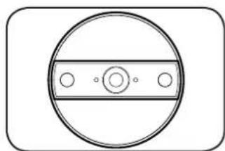
natural_image
Simple circular diagram with a horizontal bar and three small circles inside, enclosed in a rounded rectangle (no text or symbols)SHOOTING
| PROBLEM CAUSE | REMEDY | |
| Little or no material flow | Fluid adjustment dial too limited | Turn fluid adjustment dial further out clockwise |
| Air pressure too low | Increase air pressure at the compressor | |
| Turn air regulator valve further out clockwise on gun | ||
| Material too thick | Thin material | |
| Nozzle clogged | Clean nozzle | |
| Material leaking | Nozzle loose Tighten nozzle | |
| Nozzle worn | Contact Ozito for replacement spare parts | |
| Spray pattern is heavy in the middle | Fan requires adjustment | Turn fan adjustment dial further out anti-clockwise |
| Air pressure too low | Increase air pressure at the compressor | |
| Turn air regulator valve further out clockwise on gun | ||
| Spray pattern heavy at the edges | Fan requires adjustment Turn fan adjustment dial in clockwise | |
| Air pressure too high | Reduce air pressure at the compressor | |
| Turn air regulator valve further in clockwise on gun | ||
| Spray jet pulsates | Material in paint pot running out Refill paint pot | |
| Nozzle clogged | Clean nozzle | |
| Material too thick | Thin material | |
| Pattern runs or sags | Too much material is being applied | Turn fluid adjustment dial further in clockwise |
| Increase spray speed | ||
| Material is too thin | Thicken material by adding more paint | |
| Too much overspray | Gun too far from the spray surface | Reduce distance & turn fluid adjustment dial further in clockwise to reduce the amount of paint being applied. |
| Pattern is very light and splotchy | Material is too thick | Thin the material |
| Moving the spray gun to fast | Decrease spray speed | |
SPARE PARTS
Nozzle
Needle
Assembly
Assembly
SPASGGFK-S11A
SPASGGFK-S3
Filter
SPASGGFK-S43
Spare parts can be ordered from the Special Orders Desk at your local Bunnings Warehouse.
For further information, or any parts not listed here, visit www.ozito.com.au or contact Ozito Customer Service:
Australia 1800 069 486
New Zealand 0508 069 486
E-mail: enquires@ozito.com.au

GENERAL AIR TOOL SAFETY WARNINGS

WARNING! Read all safety warnings and all instructions. Failure to follow the warnings and instructions may result in electric shock, fire and/or serious injury.
Save all warnings and instructions for future reference. The term "power tool" in the
warnings refers to your mains-operated (corded) power tool or battery-operated (cordless) power tool.
- Work area safety
a. Keep work area clean and well lit. Cluttered or dark areas invite accidents.
b. Do not operate power tools in explosive atmospheres, such as in the presence of flammable
liquids, gases or dust. Power tools create sparks which may ignite the dust or fumes.
c. Keep children and bystanders away while operating a power tool. Distractions can cause you to lose control.
d. Dress properly. Do not wear loose clothing or jewellery. Keep your hair, clothing and gloves away from moving parts. Loose clothes, jewellery or long hair can be caught in moving parts.
e. Check the maximum pressure rating of any tools or accessories that you intend using with the compressor. The output pressure of the air from the compressor must be regulated so that it never exceeds the rated pressure of the tool or accessory.
f. Always wear safety goggles or glasses when using the air compressor. Never point the nozzle of an accessory towards any part of your body or towards another person.
g. Use safety equipment including safety goggles or shield, ear protection, breathing or respirator mask and protective clothing.
h. The tool must be used only for its prescribed purpose. Any use other than those mentioned in this Manual will be considered a case of misuse. The user and not the manufacturer shall be liable for any damage or injury resulting from such cases of misuse.

WARNING! In the event that an air line is cut or broken, the air supply must be turned off at the compressor. A broken air line which is not supported is extremely dangerous and can whip around very quickly, both with the capability of striking people, and blowing foreign particles into the air.
- Do not attempt to catch the air line but immediately keep bystanders well clear and turn off the air supply to the hose, turn off the compressor at the On / Off button, and then remove the hose from the compressor.
- This appliance is not intended for use by persons (including children) with reduced physical, sensory or mental capabilities, or lack of experience and knowledge, unless they have been given the supervision or instruction concerning use of the appliance by a person responsible for their safety.
• Children should be supervised to ensure that they do not play with the appliance.

SPRAY GUN SAFETY WARNINGS

WARNING!
This appliance is not intended for use by persons (including children) with reduced physical, sensory or mental capabilities, or lack of experience and knowledge, unless they have been given supervision or instruction concerning use of the appliance by a person responsible for their safety.
Using an Extension Hose
Always use an approved extension hose suitable for the air input of this tool. Before use, inspect the hose for signs of damage, wear and ageing. Replace the extension hose if damaged or defective.
When using an hose on a reel, always unwind the lead completely.
It is recommended that the hose is a maximum of 25m in length.
NEVER under any circumstances aim the nozzle at another person or animal.
• In the event of an injury occurring, seek medical advice immediately.
- The spray gun must not be used for spraying flammable paints and solvents with a flash point of less than 21^ .
• Always ensure there is adequate ventilation when spraying.
• The use of ear protection is recommended.
- Eye protection is recommended to keep hazardous vapours and liquids out of eyes.
• Always wear a face mask when spraying.
• Always read the paint manufacturers thinning instructions before using.
- Always keep the spray nozzle in place during use. Never allow the spray to come in direct contact with the skin.
- Never immerse the spray gun in liquid.
- The spray gun must not be cleaned by using flammable liquids with a flash point of less than 21^ .
NEVER spray near a naked flame, including an appliance pilot light.
NEVER smoke whilst spraying.
NEVER allow children to operate or play with the spray gun.
- Before cleaning, always disconnect the appliance from the air supply.
• Always disconnect from air supply when refilling the paint pot.
• After every use ensure you clean your spray gun thoroughly.
NEVER use the spray gun outside when it is raining.
DESCRIPTION OF SYMBOLS
| Warning | | Read instruction manual |
| Wear ear protection | | Wear eye protection and breathing mask |
| ml/min | Millilitres per minute | cfm | Cubic feet per minute |
CARING FOR THE ENVIRONMENT

Power tools that are no longer usable should not be disposed of with household waste but in an environmentally friendly way. Please recycle where facilities exist. Check with your local council authority for recycling advice.

Recycling packaging reduces the need for landfill and raw materials. Reuse of recycled material decreases pollution in the environment. Please recycle packaging where facilities exist. Check with your local council authority for recycling advice.
- WARRANTY
- YEAR REPLACEMENT WARRANTY
- WARNING
- KNOW YOUR PRODUCT
- GRAVITY FEED SPRAY GUN
- SETUP & PREPARATION
- ASSEMBLY
- Inserting the Filter
- Fitting the Paint Pot
- Attaching to Compressor
- PREPARATION
- NOTE: FOR BEST RESULTS, SURFACE PREPARATION AND PAINT THINNING ARE THE TWO MOST IMPORTANT AREAS. ENSURE ALL SURFACES ARE FREE OF DUST, DIRT AND GREASE.
- Thinning
- ADJUSTING THE SPRAY GUN
- Variable Trigger
- Fluid Adjustment Dial
- Air Regulator Valve
- ADJUSTING THE SPRAY GUN CONT. 5
- Fan Adjustment Dial
- Choosing Spray Patterns
- SPRAYING TECHNIQUE
- Helpful Hints
- CLEANING PROCEDURE TROUBLI
- SHOOTING
- SPARE PARTS
- GENERAL AIR TOOL SAFETY WARNINGS
- SPRAY GUN SAFETY WARNINGS
- WARNING!
- Using an Extension Hose
- DESCRIPTION OF SYMBOLS
- CARING FOR THE ENVIRONMENT
- Ozito
- TOUCH-UP GRAVITY FEED SPRAY GUN
Brand : Ozito
Model : ASG-GFK
Category : Paint gun