
XS-AW850 - Car speaker SONY - Free user manual and instructions
Find the device manual for free XS-AW850 SONY in PDF.


| Type | Car subwoofer |
| Model | XS-AW850 |
| Speaker size | 8 inches (20 cm) |
| Impedance | 4 ohms |
| Power handling (RMS) | 150 W |
| Power handling (peak) | 300 W |
| Frequency response | 30 Hz - 1 kHz |
| Sensitivity | 90 dB/W/m |
| Mounting depth | 4.3 inches (109 mm) |
| Mounting cut-out diameter | 7.1 inches (180 mm) |
| Weight | 5.5 lbs (2.5 kg) |
| Power supply | 12 V DC (vehicle electrical system) |
| Cone material | Polypropylene with mica |
| Surround material | Rubber |
| Features | Heavy-duty magnet, high power handling, deep bass reproduction |
| Enclosure type recommended | Sealed or ported box (0.5-1.0 cu ft) |
| Care & cleaning | Wipe with dry soft cloth; avoid moisture and solvents |
| Safety | Keep away from water, use correct polarity, disconnect vehicle battery before installation |
| Spare parts | Contact Sony support for replacement grilles or mounting hardware |
| Repairability | Professional recone service recommended for blown speakers |
| General information | Designed for car audio systems; requires external amplifier for best performance |
Frequently Asked Questions - XS-AW850 SONY
User questions about XS-AW850 SONY
0 question about this device. Answer the ones you know or ask your own.
Ask a new question about this device
Download the instructions for your Car speaker in PDF format for free! Find your manual XS-AW850 - SONY and take your electronic device back in hand. On this page are published all the documents necessary for the use of your device. XS-AW850 by SONY.
USER MANUAL XS-AW850 SONY
• Before making any connections, disconnect the ground terminal of the car battery to avoid short circuits.
- Be sure to use speakers with an adequate power rating. If you use small capacity speakers, they may be damaged.
- Do not connect the ⊙ terminal of the speaker system to the car chassis, and do not connect the ⊙ terminal of the right speaker with that of the left speaker.
• In-tall the input and output cards away from the power supply lead as running them close together can generate some interference noise.
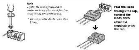
Make the terminal connections as illustrated below.

Hole on the power supply
- Convert the +12 V power supply load only after all the other mode has been connected.
- Be sure to correct the ground head of the unit
secure to a metal surface of the car. A loose connection may cause the amplifier to malfunction. - In some cases, the muscle unital load of the amplitude to the muscle tensile.
-
Use the power supply tool with a four-inch and 25 A1
-
Place the face in the person simply look as close as possible to the eye battery.
• Make sure that the basis to be connected to the +12 V and GND terminals of this unit are larger than 16 Gauss (A78C). It is have a such kind of use that 5 mm
• Diter's using the options RC 45 power source anchoring and, usual that normal for power are.
Input Connections
High Level Input Connection
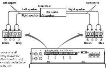
flowchart
graph TD
    A["White"] --> B["Left speaker"]
    C["Grey"] --> D["Left speaker"]
    E["Brown"] --> F["Right speaker"]
    G["Blue"] --> H["Right speaker"]
    I["Car audio"] --> J["Front Rear"]
    K["Output port"] --> L["Output port"]
Line Input Connection

Speaker Connections
4-Speaker System

Direct speaker cord connection

5 channel Active Subwoofer
Operating Instructions
Owner's Record
The model and serial numbers are located on the bottom of the unit.
Refer to those numbers wherever you call down your Story dealer repeating this product.
Mode. No. 35 AWED Serial No.
XS-AW850
Sony Corporation 1999 Printed in USA
Features
• Maximum power output of 50 watts. - 4 (at 4
ohms + 120 watts (at 6 ohms, subwoofer). - Direct connections can be made with the speaker outputs of your car radio if it is not equipped with the line output (high level input connection).
- High-pass filter circuit built in. - Protection circuit provided. - Pulse power supply* for stable, regulated output power.
Pulse power supply This and has a fault in power ratings which are not the power supplied by the DC 12 Year entry into high good levels using a constant indicator circuit. These values are aligned up by the fault in pulse, transientor and several into well position and negative stress supplies infer being answered numerical current again. This is no regulate shallowing voltage from its car battery. The high output power supply system provides a highly efficient power setup with low resistance output
Location and Function of Controls
[1] Cut-off frequency adjustment control
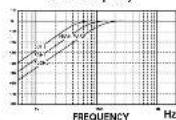
Sets the cut-off frequency (50-150 Hz) for the high-pass filters. Cut-off frequency
2 MODE select switch
The switch can be used to change the subwoofer output as follows.
FRONT: Outputs the input signal to the FRONT input jack.
F+R: Outputs the input signal to the FRONT and REAR input jacks.
3 PHASE select switch (Subwoofer only)
Use this switch in charge the phase of the reproduced sound to match your audio system.
4 LEVEL control
Turn this control to adjust the subwoster output level.
[5] POWER/PROTECTOR indicator
Lights up in green while the unit is in operation. The color will change from green to amber and the unit will shut down when the protection circuit is activated if a DC current is generated.


Installation
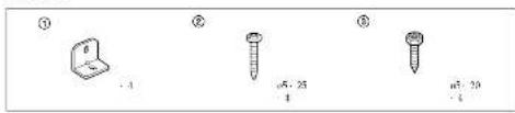
Parts list
Before installation
- Choose the installation location carefully so that the unit does not interfere with driving and/or visibility.
-
Avoid installing the unit, where it would be subject to high temperatures, such as from direct sunlight or heater exhaust, or where it would be satisfied. In dual, dual, or convexly vibration.
This unit may cause interference in the car audio or other A/V devices. If this occurs, relocate the unit at least 51 cm from the affected device. -
Use only the supplied mounting hardware for a sale and secure installation.
- Consult your nearest 500 dealer for the location of an outdoor installer if your required
of all such assistance.
Note on mounting board (not supplied)
It is recommended that a moving result at 3.5% or any installation. The area should be the other than 15 mm ^2 /m ^2 and to accept the supplied moving score.
Dimensions
Unit mm (m.)


1
Fasten the fittings ① securely to the unit with the screws ②.

2
Fasten the unit securely to the mounting board with the screws ③.

natural_image
Technical line drawing of a mechanical housing or enclosure with mounting holes and a circular vent (no text or symbols)Specifications
AUDIO POWER SPECIFICATIONS
POWER OUTPUT AND TOTAL HARMONIC DISTORTION
22 watts per channel minimum continuous average power into 4 ohms, both channels driven from 100 Hz to 20 kHz with no more than 1% total harmonic distortion.
Other Specifications
Speaker section
Wooler 20 cm, cone type
Impedance of crim
Power amplifier section
Circuit system OTL (https://pans.com/nerisa)
Pulse power supply
Inputs RCA pin jacks
High level input connector
Speaker impedance = 0 (s/kPa)
Maximum outputs Front/Rear outputs:
50 watts - 4 (at 4 ohms)
Subwoofer output:
120 walls - 1 (s) 6 of
Rated outputs (supply voltage at 14.1 V)
Front/Rear outputs:
- With · (100H)=2.5(H)_2 1% THP = 4 ohms
Subwoofer output
60 watts (110 Hz, 1'S THD), at
fr ohms]
Frequency response
Front/Rear outputs:
50 Hz - 50 kHz (dB)
Harmonic distillation
Front/Rear OT % or less (al
1 kHz)
Subwoofer 100% or less (at
Input sensitivity
0.7V (RCA pin jacks)
8.0 V (High level input)
High-pass filter 30 = 150 Hz, -12 dB/oct
System Section
Power requirements
12 V DC car battery
(negative)
Power supply voltage 10.5-16V
Current drain at rated output: 19 A
Remote input: 1.5 mA
Approx. 380, 226, 190 mm
(w)/h/d)(15.9-7):in) not
incl. projecting parts and controls
Alloye, Varnes (1 kg (1.4 lb))
Supplied accessories
Mounting screws (p5 20:4,
a5. 254), Filings [4],
Terminal Cap
Optional accessor
Connecting cord for power
amplifier RC-46
Design and specifications are subject to change
without notice.
Precautions
• This unit is designed for negative ground 12 V DC operation only.
- Low speakers with an impedance of 4 abres.
• Do not correct any active speakers (with bell-in
amplifiers) to the speaker terminals of the unit.
Doing so may damage the active speakers.
- Avoid installing the unit in areas subjects to high temperature such as from direct
— high temperatures such as heat direct sunlight or heat air from the heater.
— Rain or moisture
— dust or dirt
- If your car is parked in direct sunlight and there
is a considerable rise in temperature inside the
car, allow the unit to cool down before use.
- Be sure to install the unit horizontally so that the
If that at the existing section of its H/I will be covered with carpet etc.
• If this unit is placed too close to the car radio or
antenna, interference may occur. In this case.
relocate the amplifier away from the car radio or
antenna.
- If no power is being supplied to the master unit,
This result simplifies the process of
circuit* to protect the transistors and speakers if
the amplifier malfunctions. Do not attempt to test
the protection circuit by covering the heat sink or
overloading the circuit.
- Do not use the unit on a weak battery as its
optimum performance depends on a good power
supply
- For safety leaders, keep your car audio volume modems so that you can still have sounds.
moderate so that you can still hear sounds outside your car.
Fuse Replacement
If the fuse blows, check the power connection and replace for fuse, if the fuse blows again after
replace the case, if the case moves again after replacement, there may be an internal malfunction.
In such a case, I will tell your wishes. Sorry denker.

Warning
When replacing the fuse, be sure to use one matching the amperage stated above the fuse holder. Never use a fuse with an amperage rating, exceeding the one supplied with the unit as this could damage the unit.
*Protection circuit
This equifier is provided with a protection circuit.
actuate six or DC current is general.
The color of the PETER/PROTECT OR SIMANS' skin change from green to gray, and the vial shell flat dry.
If this happens, I've of the connected answer. Take our me
cassatic lape or disc, and delineate the cause of po
reconstruction. If the required tax provisions, not and live
The following table is provided in the image.
If you have any questions or problems concerning
your visit that are not covered in this manual.
please consult your nearest Sorry dealer.
Troubleshooting Guide
I've following checklist will assist in the connection of most problems which you may encounter with your unit. Before going through the checklist below, refer to the connection and operating procedures.
| Problem | Cause/Solution |
| The POWER/PROTECTOR Indicator does not light up. | The bus is power. → Replace the race with a new one. |
| The ground level is not securely connected. → Enable the ground level exactly to a frontal point of the crr. | |
| The voltage going into the remote terminal is too low. | |
| → The control motor and load terminals. → Turnar the motor unit. | |
| → The electric pluses for many amplifiers. → Use a relay. | |
| Check the rotary voltage (0.5 - 16 V). | |
| The remote control level of the car stops is not connected to the remote terminal which making a ring input connection. → Use to connect the remote control level of the car stops in the remote terminal. | |
| - The POWER/PROTECTOR indicator masks. | The speaker with suitable impedance [4 U] |
| - The unit heads up abnormally. | The speaker outputs are short-circuited. → Heavy the cause or the shortcircuit. |
| Alternator noise is heard. | The power connecting lines are installed too close to the RCA pin ends. → Keep the leads every turn the cords. |
| The ground level is not securely connected. → Enable the ground level exactly to a frontal point of the crr. | |
| Negative speaker leads are touching the car chasses. → Keep the leads away from the car chasses. | |
| The subooster sound is too low. | The level adjustment contact is set to the "MEN" position. |
The subwoofer sound is too low. The level adjustment contact is set to the "MIN" position.
Brand : SONY
Model : XS-AW850
Category : Car speaker