
PL-7 - Remote control ALLEN & HEATH - Free user manual and instructions
Find the device manual for free PL-7 ALLEN & HEATH in PDF.


| Product Type | Remote Control with LCD Display |
| Brand | Allen & Heath |
| Model | PL-7 |
| Display Type | 2 x 16 Character LCD |
| Backlit | Yes |
| Connection Interface | PL-Anet (RS485) via RJ45 |
| Cable Type | CAT5 STP (Shielded Twisted Pair) |
| Maximum Distance | Up to 300m (1000 ft) with PL-9 hub |
| Maximum Units in Daisy Chain | 8 PL-7 units (depending on configuration) |
| Power Supply | +20V DC via PL-Anet |
| Mounting Type | Wall cavity or custom furniture (with fixing holes) or free-standing (rubber feet) |
| Compatible Systems | iDR-4, iDR-8 |
| Internal Device Support | Accepts PL-3 or PL-4 wall plate module (optional kit) |
| Spare Parts Kit | Part number 003-862 (includes front panel and cables) |
| Termination Plug | Included for end-of-chain use |
| Configuration | Via iDR System Manager software |
| Displayable Information | Day/time, iDR unit name, patch name, user-defined text (16 chars per line) |
| Compliance | European EMC directives 89/336/EEC & 92/31/EEC |
| Operating Temperature | Not specified (assume typical indoor) |
| Care and Cleaning | Clean with a soft dry cloth |
| Safety | Observe local installation standards; ensure proper grounding via PL-Anet shield |
Frequently Asked Questions - PL-7 ALLEN & HEATH
User questions about PL-7 ALLEN & HEATH
0 question about this device. Answer the ones you know or ask your own.
Ask a new question about this device
Download the instructions for your Remote control in PDF format for free! Find your manual PL-7 - ALLEN & HEATH and take your electronic device back in hand. On this page are published all the documents necessary for the use of your device. PL-7 by ALLEN & HEATH.
USER MANUAL PL-7 ALLEN & HEATH
Introduction Welcome to the Allen & Heath PL-7 LCD display panel. This is part of the PL-Series of daisy chainable wall plates and remote controllers available for the iDR-4 and iDR-8 audio mix processor systems. Adding these devices greatly extends the capability of the system. The PL-7 features a 2 x 16 character LCD able to display important system information and pre-programmed user text at locations remote from the iDR main unit. The display is backlit to ensure it can be easily read in all lighting conditions. Each line may be separately configured by the installer using the iDR System Manager software to display:
Day and time
iDR unit name
Current patch name
User defined text up to 16 characters per line
The PL-7 module has an attractively styled face plate with fixing holes for wall cavity or custom furniture mounting, and rubber feet for free standing operation. It connects to the IDR PL-Anet serial port using CAT5 cable which can be conveniently routed around the installation to provide for a network of different types of PL remote controllers. Two underside RJ45 sockets connect the input and pass PL-Anet on to the next PL device. A terminator plug is provided to be plugged in if the PL-7 is the last unit in the chain.
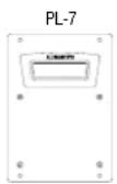
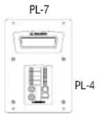
An optional face plate with pre-punched cutout is separately available if you wish to mount a wall plate controller assembly such as the PL-3 or PL-4 within the PL-7 module itself. This provides remote controls such as switches, rotary encoder, LED displays and infra-red detector in addition to the LCD display. The fitted PL module is connected to the PL-Anet network within the PL-7. For information on the full range of PL products available visit our web site http://www.allen-heath.com.
The PL-7 can also be ordered with the PL-4 controller already fitted.
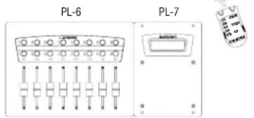
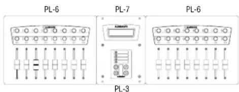
Applications A few examples are shown in the diagram here. By itself the PL-7 provides a convenient display of system information at any point within an installation. With another PL device such as the PL-4 fitted internally it adds remote control and additional LED display within a single compact module. Together with one or more similarly styled PL-6 fader or PL-10 rotary encoder modules it provides additional control and/or information display to create an easy to use remote mix station. This is ideally suited to installations such as multi-function venues and houses of worship where a variety of regular events may be controlled by non-skilled operators at different locations.
Planning the system An installation may comprise several different combinations of PL devices, for example room wall plates for volume control and source select, fader controllers and one or more PL-7 modules. The maximum number of PL devices that can be connected depends on their type and the distances involved. You can connect up to 8x PL-7 units in a system, but fewer if long distances or additional PL types are involved. Long distances up to 300m (1000'), and star point connection are possible if the optional PL-9 PL-Anet hub is used. It is important that you check the possibilities first by referring to the PL Combinations Calculator spreadsheet available from the Allen & Heath web site.

This product complies with the European Electromagnetic Compatibility directives 89/336/EEC & 92/31/EEC.
NOTE: Any changes or modifications to the equipment not approved by Allen & Heath could void the compliance of the equipment. Whilst we believe the information in this guide to be reliable we do not assume responsibility for inaccuracies. We also reserve the right to make changes in the interest of further product development.
Copyright© 2008 Allen & Heath Ltd. All rights reserved.
IMPORTANT :
Observe the local installation standards which may apply regarding the grade of cable and installation methods. Test for correct wiring and installation before switching the equipment on. Do not install the equipment where it is subject to moisture, heat or excessive movement.
Connect this equipment to the Allen & Heath PL-Anet port only. Connect only PL equipment to PL-Anet.
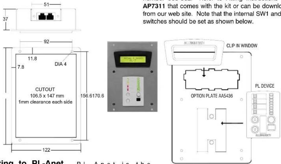
Installing the PL-7 Cutting template details are shown here for mounting the PL-7 into a wall or furniture. Secure the unit in place using 4x fixing screws up to 3.5mm diameter. The chassis and plate are grounded through the PL-Anet cable shield. Check your installation requirements to see if any additional safety grounding is needed.
Connecting to PL-Anet PL-Anet is the
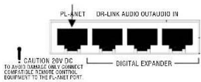
proprietary Allen & Heath system for daisy chaining PL remote controllers. It is an RS485 serial connection that uses CAT5 STP cable to communicate between devices over long distances. The connection includes +20V DC to power the connected devices. Use flame retardant CAT5 STP (shielded twisted pair) RJ45 cables. The iDR-8 main unit port is shown here.
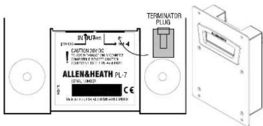
The PL-7 has underside RJ45 ports for connecting to PL-Anet. These are recessed so that the cables can be hidden from view. The IN port connects to the previous unit in the chain. The OUT port connects to the next unit, or end of chain termination. As with any RS485 system, the last PL device needs to have a terminating resistor fitted to its output port. The PL-7 is shipped with an RJ45 terminator plug with this resistor built in. If the PL-7 is the only unit or last unit connected make sure the terminator is plugged into its output port.
Testing the wiring Before powering up the system make sure all the wiring is inspected and continuity tested. This is important as wiring errors may result in damage to the equipment.
If further assistance is required please visit the our web site www.allen-heath.com or contact Allen & Heath technical support in your territory.
flowchart
graph TD
    A["PL-7 Top view"] --> B["PL Device Fitted"]
    A --> C["NOT FITTED"]
    B --> D["SW1- ALL OFF (DOWN)"]
    B --> E["SW2- ALL ON (UP)"]
    C --> F["SW1- ALL ON (UP)"]
    C --> G["SW2- ALL OFF (DOWN)"]
    H["Internal PL-Anet OUT IN"] --> I["IN"]
    H --> J["OUT"]
    K["Internal PL Device Underside view"] --> L["IN"]
    K --> M["OUT"]
Fitting an internal PL device A single wall plate sized module such as the PL-3 or PL-4 may be fitted into the PL-7. This adds switch and infra-red control to the PL-7.
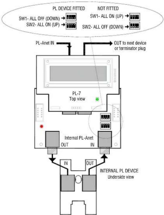
A kit of parts including replacement front panel and internal cables is available from Allen & Heath, part number 003-862. Refer to Fitting Instructions sheet AP7311 that comes with the kit or can be downloaded from our web site. Note that the internal SW1 and SW2 switches should be set as shown below.
Using the PL-7 Ensure that the IDR PL-Anet port is enabled with its green 'active' LED lit. If not, use the iDR System Manager software Communications Option menu to enable the port. Plug in the PL-Anet cable. The screen should display icons on the toolbar for each PL device it recognises. If an internal PL device is fitted then it will be recognised in the chain before the PL-7. Check that the PL-7 LCD lights up and displays text. The 2x16 character LCD display is configured using the iDR System Manager software. Refer to the Help file that comes with the software.
We hope you enjoy using the PL-7.
Brand : ALLEN & HEATH
Model : PL-7
Category : Remote control