DADM-TK-65 - Nicht kategorisiert Festo - Kostenlose Bedienungsanleitung
Finden Sie kostenlos die Bedienungsanleitung des Geräts DADM-TK-65 Festo als PDF.


| Produkttyp | Pneumatikzylinder |
| Modell | DADM-TK-65 |
| Hersteller | Festo |
| Kolbendurchmesser | 65 mm |
| Hub | Variabel (je nach Ausführung) |
| Betriebsdruck | 2…10 bar |
| Umgebungstemperatur | -20…+80 °C |
| Werkstoff | Aluminium, Edelstahl |
| Gewicht | Ca. 1,5 kg |
| Schmierung | Geschmiert (Lebensdauerschmierung) |
| Anschluss | G1/4" |
| Kolbenstange | Edelstahl, gehärtet |
| Dämpfung | Elastische Dämpfung an beiden Enden |
| Schutzart | IP54 |
| Wartung | Keine regelmäßige Wartung erforderlich |
| Reinigung | Mit feuchtem Tuch und mildem Reinigungsmittel |
| Sicherheitshinweise | Vor Wartung Druck entlüften, Quetschgefahr beachten |
| Ersatzteile | Dichtungssätze, Kolbenstangen |
| Reparatur | Durch autorisiertes Fachpersonal |
Häufig gestellte Fragen - DADM-TK-65 Festo
Benutzerfragen zu DADM-TK-65 Festo
0 Frage zu diesem Gerät. Beantworten Sie die, die Sie kennen, oder stellen Sie Ihre eigene.
Eine neue Frage zu diesem Gerät stellen
Laden Sie die Anleitung für Ihr Nicht kategorisiert kostenlos im PDF-Format! Finden Sie Ihr Handbuch DADM-TK-65 - Festo und nehmen Sie Ihr elektronisches Gerät wieder in die Hand. Auf dieser Seite sind alle Dokumente veröffentlicht, die für die Verwendung Ihres Geräts notwendig sind. DADM-TK-65 von der Marke Festo.
BEDIENUNGSANLEITUNG DADM-TK-65 Festo
Assembly instructions (Original instructions)
8072099
2017-05d
[8072101]
FESTO
Festo SE & Co. KG
Ruiter Straße 82
73734 Esslingen Germany
+49 711 347-0
www.festo.com
Reciprocating motion kit DADM-TK
1. Applicable documents
All available documents for this product → www.festo.com/pk
→ Operating instructions for rotary indexing table 5
2. Safety
- Observe the safety information (→ Applicable documents).
- Comply with tightening torques (→ Table).
3. Intended use
Reciprocating motion kit DADM-TK:
Conversion of the rotary indexing table DHTG to reciprocating motion.
- Scope of delivery
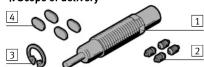
1 Shock absorber (1x) 2 Stop pin with O-ring (4x) 3 Retaining ring (1x)
4 Flat seal (4x)
- Not in scope of delivery
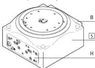
5 Rotary indexing (1x) table DHTG (B) Stop plate (1x)
(H) Shock absorber (1x) plate
- Screw sizes and tightening torques M_A^1)
| DADM-TK | 65 | 90 | 140 | |||
| [2] | Stop pin M4 | |||||
| [Nm] | 1.5 | |||||
| (A) Screw M5x16 (3x) | M5x16 (5x) | M6x16 (5x) | M6x20 (5x) | |||
| [Nm] | 2.9 | 5.9 | ||||
| (F) Flow control valve | GRLA-M5-B | GRLA-1/8-QS-8-D | ||||
| [Nm] | 1.5 | 5.5 | ||||
| (G) Screw M4x16 (4x) | M4x16 (5x) | M6x16 (6x) | M6x25 (6x) | |||
| [Nm] | 2.9 | 9.9 | ||||
220
7. Preparations for mounting
- Unlock rotary indexing table 5 (→ Applicable documents).
To unlock: - Pressurize the supply port A with at least 4 bar.
→ The rotary table can be turned freely.
- Switch off compressed air.
• Exhausting the rotary indexing table.
- Mounting
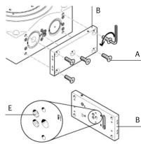
- Unscrew screws (A).
- Remove stop plate (B).
[Non-Text]
- Check stop plate (B).
The stop plate (B) contains
drill holes (E) or threads (E). - For drill holes (E)
→ Section 8a - For threads (E)
→ Section 8b.
8a. For drill holes (E)
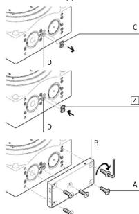
- Remove O-rings (C) from the drill holes (D).
- Place two seals 4 on the drill holes (D).
- Fasten the stop plate (B) using the screws (A).
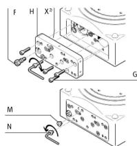
• Unscrew flow control valve (F). - Unscrew screws (G).
- Remove shock absorber plate (H).
- Remove O-rings (J) from the drill holes (K).
- Place two seals 4 on the drill holes (K). Turn the rotary table.
→ Left drive piston (L) comes forward 2). - Push the shock absorber 1 into the drive piston (L).
- Fasten the shock absorber 1 with the retaining ring 3.
- Check remaining O-rings
for correct fit. - Fasten shock absorber plate (H) ^3) with the screws (G).
- Screw throttle valve (F) in tightly.
- Remove the plugs (M) and (N).
- Place two seals 4 on the drill holes (K). Turn the rotary table.
→ Left drive piston (L) comes forward 2). - Push the shock absorber 1 into the drive piston (L).
- Fasten the shock absorber 1 with the retaining ring 3.
for correct fit. - Fasten shock absorber plate (H) ^3) with the screws (G).
- Screw throttle valve (F) in tightly.
- Remove the plugs (M) and (N).

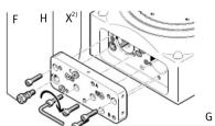
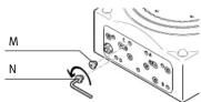

Information
Four stop pins 2 and four O-rings (J) are left over.
8b. For threads (E)
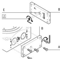
- Tighten two stop pins 2 in the threads (E) of the stop plate (B).
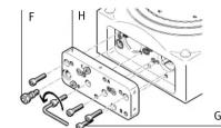
- Fasten the stop plate (B) using the screws (A).
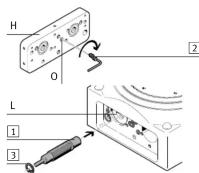
- Unscrew flow control valve (F). - Unscrew screws (G). - Remove shock absorber plate (H).
- Tighten two stop pins 2 in the threads (O) of the shock absorber plate (H).

Information
Four seals 4 are left over.
9. After mounting
During reciprocating motion, locking is separated from rotation.
- Always actuate turn (right/left) and unlock/lock with a controller accordingly (→ Applicable documents).
Marke : Festo
Modell : DADM-TK-65
Kategorie : Nicht kategorisiert