CRDSNU-25-50-P-A - Nicht kategorisiert Festo - Kostenlose Bedienungsanleitung
Finden Sie kostenlos die Bedienungsanleitung des Geräts CRDSNU-25-50-P-A Festo als PDF.


| Produkttyp | Kolbenstangen-Zylinder (Rundzylinder) |
| Modell | CRDSNU-25-50-P-A |
| Kolbendurchmesser | 25 mm |
| Hub | 50 mm |
| Pneumatikanschluss | G1/8 |
| Kolbenstangengewinde | M10x1,25 |
| Endlagendämpfung | Elastische Dämpfungsringe/-platten (beidseitig) (Typ P) |
| Betriebsdruck | 1 ... 10 bar |
| Umgebungstemperatur | -20 ... +80 °C |
| Theoretische Kraft (Vorlauf) bei 6 bar | 295 N |
| Theoretische Kraft (Rücklauf) bei 6 bar | 247 N |
| Gewicht | 465 g (bei 50 mm Hub) |
| Einbaulage | beliebig |
| Betriebsmedium | Druckluft nach ISO 8573-1:2010 [7:4:4] |
| Schmierung | ölgeschmierter Betrieb möglich (dann immer erforderlich) |
| Reinigung | Mit weichem Tuch reinigen; keine aggressiven Reinigungsmittel |
| Wartung | Wartungsfrei durch Lebensdauerschmierung |
| Sicherheitshinweise | Vor Arbeiten Druckluftversorgung abschalten und gegen Wiedereinschalten sichern |
| Verwendungszweck | Transport von Lasten |
| Hersteller | Festo SE & Co. KG |
| Zubehör | Siehe Katalog unter www.festo.com/catalogue |
Häufig gestellte Fragen - CRDSNU-25-50-P-A Festo
Benutzerfragen zu CRDSNU-25-50-P-A Festo
0 Frage zu diesem Gerät. Beantworten Sie die, die Sie kennen, oder stellen Sie Ihre eigene.
Eine neue Frage zu diesem Gerät stellen
Laden Sie die Anleitung für Ihr Nicht kategorisiert kostenlos im PDF-Format! Finden Sie Ihr Handbuch CRDSNU-25-50-P-A - Festo und nehmen Sie Ihr elektronisches Gerät wieder in die Hand. Auf dieser Seite sind alle Dokumente veröffentlicht, die für die Verwendung Ihres Geräts notwendig sind. CRDSNU-25-50-P-A von der Marke Festo.
BEDIENUNGSANLEITUNG CRDSNU-25-50-P-A Festo
natural_image
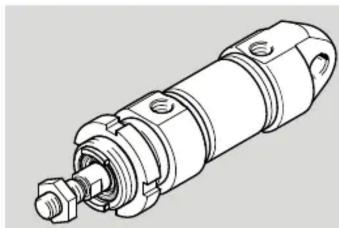
Technical line drawing of a mechanical component with no visible text or symbolsFESTO
Festo SE & Co. KG
Ruiter Straße 82
73734 Esslingen
Germany
+49 711 347-0
www.festo.com
Operating instructions
8143197
2021-01c
[8143199]

Translation of the original instructions
© 2021 all rights reserved to Festo SE & Co. KG
1 Applicable documents
i
All available documents for the product → www.festo.com/sp.
2 Safety
2.1 Safety Instructions
– Take into consideration the ambient conditions at the location of use.
- Only use the product in original status without unauthorised modifications.
– Observe labelling on the product.
- Store the product in a cool, dry, UV-protected and corrosion-protected environment. Ensure that storage times are kept to a minimum.
– Prior to mounting, installation and maintenance work: Switch off compressed air supply and secure it from being switched back on.
- Observe tightening torques. Unless otherwise specified, the tolerance is ± 20% .
2.2 Intended use
The product is intended for the transport of loads.
2.3 Training of skilled personnel
Installation, commissioning, maintenance and disassembly should only be conducted by qualified personnel.
3 Further information
- Accessories → www.festo.com/catalogue.
– Spare parts → www.festo.com/spareparts.
4 Service
Contact your regional Festo contact person if you have technical questions
→ www.festo.com.
5 Product overview
5.1 Function
The piston rod moves outwards when the cylinder chamber is pressurised. The advanced piston rod is retracted as follows:
- For double-acting cylinders, by pressurising the other cylinder chamber.
The cylinder force during advance and return is:
– different with piston rod at one end.
– identical with through piston rod.
The position of the piston can be detected by proximity switches.
5.2 Design
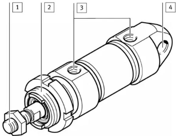
1 Male thread on the piston rod for mounting the payload
2 Male thread on the bearing cap for mounting
3 Supply ports in the bearing/end cap
4 Cross hole for mounting
Fig. 1 Sample illustration CRDSNU
5.3 Mounting
- Handle the cylinder so as to avoid any damage to the cylinder barrel and piston rod.
- Observe the following points:
– parallel mounting when using external guides
- installation without distortion
- Compliance with the permissible loads www.festo.com/catalogue
- Observe tightening torque of lock nuts on the male thread 2.
Size 12 16 20 25 32 40 50 63 80 100
Tightening torque [Nm] 15 15 40 40 60 80 100 100 550 550 on the bearing cap
Tab. 1 Tightening torques on the bearing cap
- Avoid mechanical alignment inaccuracies between the piston rod and an external guide using one of the following measures:
- absolutely precise alignment (general)
– use of a self-aligning rod coupler FK
– use of a guide unit FEN with compensating coupling
A rigid coupling impairs the service life and function of the cylinder.
5.4 Mounting Accessories
In the case of a large payload, high piston speed or when using quick exhaust valves:
- Use suitable shock absorbers or external stops.
To prevent the payload from sliding down suddenly in the event of an air supply failure in a horizontal or sloping mounting position: - Use piloted check valves.
To set the speed:
- Use one-way flow control valves in the following supply ports:
- For single-acting cylinders: GRLZ (supply air)
- For double-acting cylinders: GRLA (exhaust air)
The one-way flow control valves are screwed directly into the supply ports. Use of other accessories with a screw-in depth that is too long will damage the cushioning piston.
For position sensing with proximity sensors:
- Use proximity sensors with mounting kit.
Avoid external influence caused by magnetic or ferritic parts in the vicinity of the proximity sensors (spacing ≥ 10 mm).
6 Installation
6.1 Pneumatic Installation
- Connect tubing to supply ports.
7 Commissioning
7.1 Preparation
- Pressurise the system slowly. A soft start valve is used for gradual start-up pressurisation www.festo.com/catalogue.
With medium or large payloads or at high speeds:
- Use sufficiently large arrester fixtures. The product will tolerate the maximum velocities and payloads without external arrester fixtures
→ www.festo.com/catalogue
7.2 Processing
NOTICE!
Risk of collision due to payloads that project into the setup region of the product.
- Only turn adjusting screws while the product is stationary.
-
First of all, close the one-way flow control valves on both sides completely, then unscrew them one complete turn.
-
Pressurise the cylinder simultaneously at both ends. The piston rod moves slightly to a point of balance.
-
Exhaust the cylinder at one end. The piston rod moves to an end position.
-
Start the test run.
-
If the piston rod strikes hard against the end positions or rebounds, correct the speed using the one-way flow control valve.
8 Maintenance
8.1 Cleaning
NOTICE!
- Do not use aggressive cleaning agents.
- Do not clean the guide elements. Regularly removing the lubricant from the surface of the piston rod reduces the service life.
- Clean the product with a soft cloth.
The cylinder is furthermore maintenance-free owing to the lifetime lubrication.
9 Malfunctions
9.1 Fault clearance
Fault description Cause Remedy
| Irregular movement of the piston rod (cylinder jolts). | Lack of lubricant. Apply lubricant | in accordance with wearing parts sheet ➔ www.festo.com/spareparts. |
| One-way flow control valves restrict the flow of supply air. | Control the exhaust air flow if possible (not the supply air). | |
| Piston rod is dirty. – Clean the cylinder. – Provide covering (relubric- ate after thorough clean- ing). | ||
| Insufficient supply air (stick slip) | – Keep the tubing lines short and select suitable cross-sections. – Select correct pressure. – Keep pressure constant. | |
| Pressure is too low. Connect volume upstream. | ||
| Guide is not parallel to direction of stroke. | Use self-aligning rod coupler as in accessories ➔ www.festo.com/catalogue. | |
| Piston does not travel to end position. | Cylinder barrel is damaged. Replace cylinder. | |
| Setting screw for end-position cushioning is completely closed. | Loosen setting screw. | |
| Foreign matter in the cylinder. Filter the compressed air. | ||
| Cylinder travels to an external end stop. | Readjust the end stop. | |
| False triggering during position sensing. | Temperatures too high or too low. | Comply with permissible tem- perature range of the proximity sensors. |
| Fault at proximity sensor ➔ Instruction manual for prox- imity sensor | ||
Tab. 2 Fault clearance
10 Disposal
ENVIRONMENT!
Send the packaging and product for environmentally sound recycling in accordance with the current regulations www.festo.com/sp.
11 Technical data
| Size 12 16 20 25 32 | ||||||
| Pneumatic port | M5 | G1/8 | ||||
| Piston rod thread | M6 | M8 M10x1.25 | ||||
| End-position cushioning | P | elastic cushioning rings/plates, at both ends | ||||
| PPS | - | pneumatic cushioning, both ends, self-adjust-ing | ||||
| PPV | - | pneumatic cushioning, both ends,adjustable | ||||
| Mounting position | any | |||||
| Operating medium | Compressed air according to ISO 8573-1:2010 [7:4:4] | |||||
| Notes on theoperating/pilot medium | lubricated operation possible (in which case lubricatedoperation will always be required) | |||||
| Operating pressure | [MPa]0 | 1 ... 1 | ||||
| [psi]14 | 5 ... 145 | |||||
| [bar] | 1 ... 10 | |||||
| Ambient temperature | ||||||
| CRDSNU-... | [°C] | -20 ... +80 | ||||
| CRDSNU-...-A1 | [°C] | 0 ... +80 | ||||
| CRDSNU-...-S6 | [°C] | 0 ... +120 | ||||
| CRDSNU-...-TT | [°C] | -40 ... +80 | ||||
| Theoretical force | ||||||
| Theoretical force at 0.6 MPa(87 psi, 6 bar), advance | [N] | 68 | 121 | 188 | 295 | 483 |
| Theoretical force at 0.6 MPa(87 psi, 6 bar), return | [N] | 51 | 104 | 158 | 247 | 415 |
| Weight | ||||||
| Basic weight | [g] | 101 | 130 | 310 | 410 | 670 |
| Additional weight per 10 mm stroke | [g] | 4 | 5 | 7 | 11 | 15 |
Tab. 3 Technical data CRDSNU
| Size 40 50 63 80 100 | ||||||
| Pneumatic port | G1/4 | G3/8 | G1/2 | |||
| Piston rod thread | M12x1.25 | M16x1.5 | M20x1.5 | |||
| End-position cushioning | P | elastic cushioning rings/plates, at both ends | ||||
| PPS | pneumatic cushioning, both ends, self-adjusting | |||||
| PPV | pneumatic cushioning, both ends, adjustable | |||||
| Mounting position | any | |||||
| Operating medium | Compressed air according to ISO 8573-1:2010 [7:4:4] | |||||
| Notes on the operating/pilot medium | lubricated operation possible (in which case lubricated operation will always be required) | |||||
| Operating pressure | [MPa] 0 | 1 ... 1 | ||||
| [psi] 14 | 5 ... 145 | |||||
| [bar] | 1 ... 10 | |||||
| Ambient temperature | ||||||
| CRDSNU-... | [°C] | -20 ... +80 | ||||
| CRDSNU-...-A1 | [°C] | 0 ... +80 | ||||
| CRDSNU-...-S6 | [°C] | 0 ... +120 | ||||
| CRDSNU-...-TT | [°C] | -40 ... +80 | ||||
| Theoretical force | ||||||
| Theoretical force at 0.6 MPa (87 psi, 6 bar), advance | [N] | 754 | 1178 | 1870 | 3016 | 4712 |
| Theoretical force at 0.6 MPa (87 psi, 6 bar), return | [N] | 633 | 990 | 1682 | 2721 | 4418 |
| Weight | ||||||
| Basic weight | [g] | 1327 | 2020 | 2943 | 5891.2 | 8527.1 |
| Additional weight per 10 mm stroke | [g] | 24 | 40 | 44 | 68 | 75 |
Tab. 4 Technical data CRDSNU
- Applicable documents
- Safety
- Safety Instructions
- Intended use
- Training of skilled personnel
- Further information
- Service
- Product overview
- Function
- Mounting
- Mounting Accessories
- Installation
- Pneumatic Installation
- Commissioning
- Preparation
- Processing
- NOTICE!
- Maintenance
- Cleaning
- Malfunctions
- Fault clearance
- Disposal
- ENVIRONMENT!
Marke : Festo
Modell : CRDSNU-25-50-P-A
Kategorie : Nicht kategorisiert