CPE14-PRSEO-2 - Nicht kategorisiert Festo - Kostenlose Bedienungsanleitung
Finden Sie kostenlos die Bedienungsanleitung des Geräts CPE14-PRSEO-2 Festo als PDF.


| Produkttyp | Verteilerblock (Anschlussblock) für pneumatische Ventile |
| Modell | CPE14-PRSEO-2 |
| Marke | Festo |
| Medium | Druckluft nach ISO 8573-1:2010 [7:4:4], geschmierte Betrieb möglich |
| Betriebsdruck | -0,09 MPa ... 1,0 MPa (-0,9 bar ... 10 bar / -13 psi ... 145 psi) |
| Max. Anzugsdrehmoment für zylindrische Steckverbinder | 8 Nm |
| Montageposition | Hutschienenmontage (nur horizontal) oder Wandmontage (beliebig) |
| Umgebungstemperatur | -5 °C ... +50 °C |
| Lagertemperatur | -20 °C ... +40 °C |
| Werkstoffe Gehäuse | Polyamid |
| Werkstoffe Anschlüsse | Aluminium |
| Werkstoffe Dichtungen | Nitrilkautschuk |
| Werkstoffe Verbindungen | Verzinkter Stahl |
| Ventilplätze | Für 2 oder 3 Ventile (PRSG-2/-3); max. 6 Ventile pro Druckzone bei einseitiger Versorgung, 12 bei zweiseitiger |
| Besonderheit | Membranen entfernt für ungehinderten Durchfluss (PRSEO-Variante) |
| Zubehör | Endplatte CPE...-PRS-EP, Erweiterungsplatte CPE...-PRS-2, Blindplatten CPE...-PRSB |
| Sicherheitshinweise | Nur im Originalzustand ohne unbefugte Änderungen verwenden; Verriegelung der Ventile beachten |
Häufig gestellte Fragen - CPE14-PRSEO-2 Festo
Benutzerfragen zu CPE14-PRSEO-2 Festo
0 Frage zu diesem Gerät. Beantworten Sie die, die Sie kennen, oder stellen Sie Ihre eigene.
Eine neue Frage zu diesem Gerät stellen
Laden Sie die Anleitung für Ihr Nicht kategorisiert kostenlos im PDF-Format! Finden Sie Ihr Handbuch CPE14-PRSEO-2 - Festo und nehmen Sie Ihr elektronisches Gerät wieder in die Hand. Auf dieser Seite sind alle Dokumente veröffentlicht, die für die Verwendung Ihres Geräts notwendig sind. CPE14-PRSEO-2 von der Marke Festo.
BEDIENUNGSANLEITUNG CPE14-PRSEO-2 Festo
FESTO
Festo SE & Co. KG
Ruiter Straße 82
73734 Esslingen
Deutschland
+49 711 347-0
www.festo.com
Operating instructions
8151076
2021-03g
[8151078]

8151076
Translation of the original instructions
© 2021 all rights reserved to Festo SE & Co. KG
1 Applicable documents
i
All available documents for the product → www.festo.com/sp.
2 Safety
Safety instructions
Only use the product in original status without unauthorised modifications.
Intended use
The manifold blocks CPE...- PRS connect directional control valves to central supply ports and are intended for wall or H-rail mounting.
3 Additional information
-Accessories → www.festo.com/catalogue.
4 Product overview
Structure
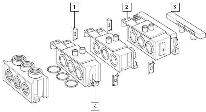
Fig.1
1 Connecting component
2 Valve spool
3 Blind plate
4 Mounting slide
Function
The manifold block CPE...-PRSG-2/-3 (double or triple) connects type CPE 5/2- or 5/3-way valves to central supply ports.
Two additional valves can be supplied with the help of the extension plate CPE...-PRS-2.
The end plate CPE...-PRS-EP can be used to create different pressure zones or a two-sided compressed-air supply.
The maximum configuration level is:
6 valves 12 valves
| - with one-sided compressed-air supply or-for every pressure zone | - with two-sided compressed-air supply |
Tab. 1
The CPE-...-PRSO-... have the diaphragms removed.
5 Assembly
Preparation
natural_image
Diagram of four connected blocks with arrows indicating direction of movement or force (no text or symbols)Fig.2
-
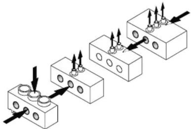
Place all manifold blocks in their assembly sequence.
-
Trace the pressure curve, e.g. with a sketch.
When using multiple pressure zones:
NOTICE
- Make sure that the diaphragms at the interface of two pressure zones remain intact.
Pressed-in diaphragms cannot be closed again. In doing so, consider removing the diaphragms of the compressed air ducts for an unobstructed flow rate.
Removing unused diaphragms:
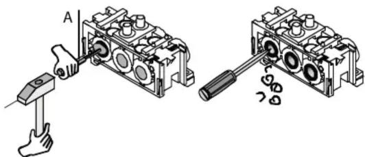
Fig.3
-
Press in the 3 diaphragms of the compressed air ducts on the manifold block from the outside inwards in accordance with the pressure curve sketch using a punch (A)
-
Deburr fracture margins and
-
Remove chips.
This time-saving method of operation results in irregular broken edges compared to precision machining.
Assembly
H-rail mounting:
- Place all manifold blocks on the H-rail in accordance with the assembly sequence.
- Press the manifold blocks on the H-rail until the mounting slides 5 engage. Linking manifold blocks:
natural_image
Technical diagram of a mechanical assembly with arrows indicating force or movement (no text or symbols)Fig.4
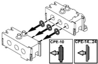
- Place one sealing ring each between each of the three compressed air ducts and press the manifold blocks together.
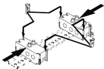
- Push a connecting component 1 onto the rail shown on both sides until it clicks into place.
Mounting the CPE valves:
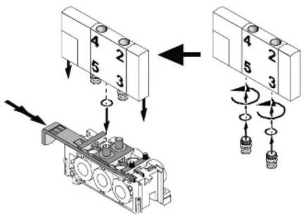
Fig.5
- Insert all valve spools 2 up to the first detent.
-
Place a seal on every compressed air outlet.
-
Screw the valve connecting fittings with attached sealing ring into ports 3 and 5 of the CPE valve.
- Place the CPE valves on the manifold block, press in and simultaneously push the valve spool to the 2nd detent. The valve spool and valve are then flush with each another.
WARNING
Observe the locking procedure!
This is the only way to prevent unsecured valves from being thrown out when the manifold is pressurised.
Procedure
- Ensure that the connected manifold blocks are installed without distortion.
- Make sure there is sufficient space for the required ports.
H-rail mounting
natural_image
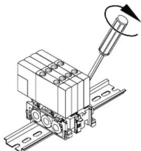
Mechanical assembly diagram showing a lever mechanism with rotating shaft (no text or symbols)Fig.6
- Tighten the locking screws of the manifold block to the H-rail.
Wall mounting
natural_image
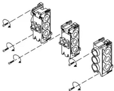
Pure mechanical assembly diagram showing three cylindrical components with mounting holes and directional arrows, no text or symbols present.Fig.7
- Screw in the following number of screws for mounting:
Component Required number of screws
| Manifold block 2 | |
| Extension plate 1 | |
| End plate 2 |
6 Installation
Pneumatic installation
- Preferably use type QS...-... round push-in fittings with cylindrical connecting thread.
- Connect the tubing for the pneumatic ports as shown in the pressure curve sketch Fig. 2.
Seal the connecting thread. Observe tightening torques → Technical data.
When using conical QS push-in fittings:
- Turn the fittings with two layers of sealing band as follows:
-First screw in by hand.
- Then use a suitable tool to turn further 2 turns, but do not screw in to the block.
-To seal unused valve positions:
-Use the type CPE...-PRSB blanking plates 3.
7 Malfunctions
| Malfunction Possible cause Remedy | ||
| Pressure loss Diaphragm | pressed in at the interface of two pressure zones | Replace the corresponding manifold block |
| Tubing connection fault Correct tubing connection fault | ||
| Audible blowing noise Seals not in intended position Check seals | ||
Tab. 2
8 Demounting
Removing CPE valves:
- Exhaust the manifold block.
- Pull the valve spool 2 one detent outwards.
Take into account the short distance between the valve spool and the mounting surface of the connecting component 1.
Disassembly of interlinked connection blocks:
natural_image
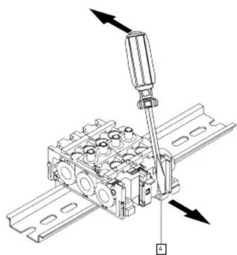
Technical line drawing of a mechanical assembly with directional arrows indicating movement (no text or symbols)Fig.8
4 Mounting slide
- Remove CPE valves.
- Press down the lock 5 and pull the valve spool completely out of the manifold block.
- Dismantle individual parts in reverse order of assembly.
Dismantling the H-rail:
- Remove CPE valves.
- Unscrew locking screw.
- Demount the interlinked connection blocks.
- Lever the mounting slides out of the manifold blocks with a screwdriver.
9 Technical data
| Type CPE-... | -10-PRS | -14-PRS | -18-PRS | -24-PRS |
| Medium | Compressed air in accordance with ISO 8573-1:2010 [7:4:4] lubricated operation possible (in which case lubricated operation will always be required) | |||
| Permissible operating pressure | -0.09 MPa ... 1.0 MPa-0.9 bar ... 10 bar-13 psi ... 145 psi | |||
| Max. permissible tightening torque for cylindrical push-in fittings | 6 Nm | 8 Nm 30 Nm | 30 Nm | |
| Mounting position | ||||
| H-rail mounting | Horizontal only | |||
| Wall mounting | Any | |||
| Permissible temperature | ||||
| Environment, medium | -5 °C ... +50 °C | |||
| Storage | -20 °C ... +40 °C | |||
| Materials | ||||
| Housing | Polyamide | |||
| Fittings | Aluminium | |||
| Seals | Nitrile rubber | |||
| Connections | Galvanised steel | |||
Tab. 3
Marke : Festo
Modell : CPE14-PRSEO-2
Kategorie : Nicht kategorisiert