
Citation X - Lautsprecher HARMAN KARDON - Kostenlose Bedienungsanleitung
Finden Sie kostenlos die Bedienungsanleitung des Geräts Citation X HARMAN KARDON als PDF.


| Produkttyp | Lautsprecher |
| Marke | Harman Kardon |
| Modell | Citation X |
| Abmessungen (B x H x T) | 228 x 78 x 78 mm |
| Gewicht | 0,7 kg |
| Stromversorgung | Lithium-Ionen-Akku 7,4 V / 2200 mAh |
| Bluetooth | Bluetooth 4.2 |
| WLAN | 802.11 b/g/n/ac |
| Sprachassistent | Google Assistant integriert |
| Freisprechfunktion | Ja |
| Akkulaufzeit | bis zu 8 Stunden |
| Ladezeit | ca. 3 Stunden |
| Wasserschutz | IPX7 (spritzwassergeschützt) |
| Reinigung | Mit einem weichen, trockenen Tuch abwischen |
| Sicherheitshinweis | Gerät nicht in Wasser tauchen, von Flüssigkeiten fernhalten |
| Ersatzteile | Nicht vom Benutzer austauschbar, nur durch autorisierten Service |
| Multiroom-Funktion | Kompatibel mit anderen Citation-Lautsprechern |
Häufig gestellte Fragen - Citation X HARMAN KARDON
Benutzerfragen zu Citation X HARMAN KARDON
0 Frage zu diesem Gerät. Beantworten Sie die, die Sie kennen, oder stellen Sie Ihre eigene.
Eine neue Frage zu diesem Gerät stellen
Laden Sie die Anleitung für Ihr Lautsprecher kostenlos im PDF-Format! Finden Sie Ihr Handbuch Citation X - HARMAN KARDON und nehmen Sie Ihr elektronisches Gerät wieder in die Hand. Auf dieser Seite sind alle Dokumente veröffentlicht, die für die Verwendung Ihres Geräts notwendig sind. Citation X von der Marke HARMAN KARDON.
BEDIENUNGSANLEITUNG Citation X HARMAN KARDON
ASSEMBLY
and
OPERATION
MANUAL
CITATION X
harman
kardon
CITATION X
ASSEMBLY & OPERATION MANUAL
INTRODUCTION
Congratulations! You are now the owner of the world's finest speaker system. Designed in the finest Citation tradition by Stewart Hegeman, Director of Engineering of the Citation Kit Division, and Donald Chave of Lowther, this speaker represents the culmination of eleven years of extensive research and experimentation in omni-directional sound.
This speaker places no limits upon performance. It can perfectly reproduce the entire complex audio spectrum with natural tone quality. The Citation X diffuses sound in a hemispheric radiation pattern by a blend of direct and reflected sound. In creating this design, the precise process of what occurs in a concert hall has now been duplicated.
Audio engineers know that approximately 80% of the sound in a good concert hall is reflected from the ceilings, walls, etc. It is this mixture of direct and reflected sound that gives music its depth and dimension, its exciting spatial quality.
The Citation X achieves precisely this effect by distributing music on vertical and horizontal planes. Conventional speakers beam the sound at you on a horizontal plane--similar to automobile headlights. In stereo, this is akin to listening to the full orchestra through two holes in the wall. Replace the conventional speakers with Citation X and the wall disappears. You are in the same room with the music. There is no ping-pong effect; no "hole-in-the-middle." All of the music is there in all of its depth and dimension and reality. For the first time, the word "presence" has been made meaningful.
The basic elements of the Citation X are the Lowther driver and the Hegeman enclosure design--a split, slot-loaded conical horn, with two 7 1/2 feet sections folded within the enclosure.
The driver is a massive Lowther unit specifically engineered for the Citation system. It provides omni-directional sound by:
* Direct radiation from front of cone.
* Radiation from the midrange "whizzer" cone which operates between 2000 and 7000 cycles.
* A stabilizer which places a damping load on the cone and acts as a diffuser and distributor of the very highs.
* Radiation from the back of the main cone which is directly coupled to the folded horn.
Features of the specially designed drive include: magnetic structure of anistropic magnetic alloy (Ticonal G) which is the most efficient magnet material known today; usable frequency range of 20 to 50,000 cps; gap flux--17,500 gauss; total flux 196,000 maxwells; aluminum voice coil for increased high frequency efficiency; twin cone construction with foam plastic front and rear suspension.
Conventional horn designs use an acoustic chamber to couple the diaphragm to the throat of the horn. In the Citation X, the chamber is removed and the driver placed directly into the throat of the horn. This eliminates the last resonating element in the horn configuration and results in absolutely smooth transfer of radiation between horn and driver.
Instead of the conventional "open mouth", the Citation X horn terminates in a slot at the base of the enclosure. This presents the horn and driver with the impedance of an infinite horn. Thus, phase shift is reduced within the horn and room reflections are prevented from entering the horn's mouth and reaching the driver. Pressure loading by the horn damps completely the mechanical resonance of the cone and its suspension.
The interior of the handsome, hand-rubbed walnut enclosure is constructed of Timblend, which has no directive resonance and is stronger than wood. The entire internal horn structure is honeycombed for strength and prevention of panel resonance.
Please read this instruction manual thoroughly prior to assembly of the speaker system. Keep it available for future reference.
SPECIFICATIONS AND FEATURES
DRIVER
* 8" unit manufactured to our specifications by Lowther Manufacturing Company, Bromley, Kent, England.
* Magnet structure is Ticonal G with a gap flux of 17,500 gauss and a total flux of 196,000 maxwells.
* Total weight of CL-1 driver is 7 1/2 pounds.
* Cone resonance is below 30 cycles per second.
* Power rating is greater than 30 watts integrated program material. Driver is protected by fuse located on rear of cabinet.
* Nominal impedance is 16 ohms.
* Usable frequency range within the Citation horn is 20-50,000 cycles per second.
* Special stabilizer to evenly disperse the high frequencies and provide loading to the cone.
* Voice coil is constructed of aluminum wire for low mass and strength.
* Double plastic foam surround (front and rear) allow tremendous excursions for exceptional low frequency response without restraining the cone. This vastly minimizes distortion.
HORN
* Split conical, slot-loaded folded horn, 7 1/2 feet per section.
* Timblend panels in a honeycomb construction are used for rigidity and elimination of panel resonances.
* Driver is coupled directly to the throat of the horn to eliminate the acoustic chamber normally found in conventional horn configurations. This removes the last resonating element in the horn design.
* Slot loading prevents room reflections from entering the mouth of the horn and reaching the driver. This minimizes the standing wave ratio within the horn and results in a relatively constant impedance reflected back to the amplifier.
SYSTEM
* Low moving mass of the cone plus horn loading provides clear articulate bass never before achieved in speaker design.
* Acoustic Balance Control to compensate for room acoustics.
* Phase distortion virtually non-existent.
* Size--20 1/8" wide x 14 1/8" deep x 36 7/8" high.
UNPACKING
After unpacking the Citation X speaker, place the small parts and driver on your workbench. Check the parts against the parts list located in the rear of this manual to make certain all parts are present.
PLEASE NOTIFY YOUR DEALER IMMEDIATELY IF A SHORTAGE IS DISCOVERED.
In the event of visible shipping damage, notify your dealer at once. If the kit was shipped to you, notify the transportation company without delay. Harman-Kardon will cooperate with you in such instances, but please note that only you can recover from the carrier for damages incurred during shipping.
WARRANTY OF HARMAN-KARDON CITATION X
For a period of 90 days following the original date of purchase, all parts supplied with the Harman-Kardon Citation X are guaranteed by the manufacturer to be free from defects in material and workmanship when put to normal use and service. This guaranty is specifically limited to the following conditions:
- To validate the warranty, the warranty card accompanying this unit must be filled out completely and returned to the factory immediately following the date of purchase.
- Harman-Kardon reserves the right to substitute replacement parts for any which may be found defective.
- The warranty is effective only as to parts which are defective at the time of sale or become defective as the result of normal operation during the 90 day period following the date of sale.
- This warranty is limited to those parts which are returned to the factory transportation prepaid, and in the judgement of Harman-Kardon are found defective under the terms of this warranty.
This warranty is in lieu of all other warranties, express or implied, and all other obligations on the part of Harman-Kardon. Harman-Kardon neither assumes nor authorizes any one else to assume for it any other liability in connection with the sale of this unit.
SERVICE POLICY
Harman-Kardon has established a special consumer service division to answer all questions pertinent to the assembly, testing, or installations of this unit. Our superbly equipped factory service department is at your disposal in the event you require assistance to obtain the specified performance. For information relating to your Harman-Kardon Citation X, please address all correspondence to:
HARMAN-KARDON, INC. CITATION KIT DIVISION PLAINVIEW, L. I., N. Y.
If your problem cannot be resolved through your own efforts and after you have received factory authorization (refer to warranty), return via Railway Express, PREPAID, to the address listed above. Carefully pack the defective part in a large, rugged container, preferably of wood, using a substantial quantity of padding such as excelsior, shredded paper, or crumpled newspaper. Attach a tag to the unit indicating your name and address and specific problem. Mentioning the other components in your installation may be of value. Harman-Kardon will inspect and repair your driver (or other components) on a time and material basis.
TOOLS REQUIRED
Only standard tools are required for the assembly of this kit. You will require a screwdriver, wire cutter, soldering iron, rosin core solder, and a hammer.
ASSEMBLY PROCEDURE
CONTROL PANEL ASSEMBLY
SEE PICTORIAL 1, FIGURE A.
Mount the following parts to the control panel. Put a check mark in the ( ) column as the parts are mounted.
STEP #
1 ( ) Fuse block, using #6-32 x 5/8" flat head machine screws, #6 internal tooth lockwashers under #6-32 hex nuts.
2 ( ) Speaker terminal block, using #6-32 x 3/4" round head machine screws, #6 internal tooth lockwashers under #6-32 hex nuts.
3 ( ) Acoustic balance control, using #3/8 internal tooth lockwasher under #3/8-32 hex nut. Make sure the locking tab falls into the small hole in the control panel before tightening the nut.
4 ( ) Coil (Notice the position of the two wires for proper orientation), using #1/4-20 x 2" binding head machine screw, #1/4 flat washer under the head of the screw. Masonite washer against the back of the coil followed with a #1/4" external tooth lockwasher and #1/4-20 hex nut.
CONTROL PANEL WIRING
1 ( ) Solder a terminal lug to one end of a 1 5/8" piece of bare wire.

FIGURE 1
TERMINAL LUG
Wires with terminal lugs should be assembled as shown in Figure 1. Lay the wire between the small tabs on the terminal lug. Bend one tab over the wire and crimp tight against the wire. Bend the other tab over and crimp against the first tab. Be sure the wire is secure and then solder. Cut off any excess wire which may extend between the tabs and the mounting hole in the terminal lug.
SEE FIGURE B, FRONT VIEW.
STEP #
2 ( ) Remove the screw from terminal #1 on the speaker terminal block. Insert the screw through the mounting hole in the terminal lug. Return the screw with the terminal lug to terminal #1. (Follow the same procedure on all wires which are connected to the speaker terminal block.)
3 ( ) Connect the free end of the bare wire to lug #1 on the fuse block. Insert the wire into the hole of the lug. Wrap the wire one half turn around the lug. Solder this connection.
4 ( ) Cut a piece of brown wire 5 1/2" long. Strip 1/4" of insulation from each end. Solder a terminal lug to one end. Connect this end to terminal #3 on the speaker terminal block. Insert the other end of the wire through hole "A" located above the speaker terminal block. Leave this end free.
5 ( ) Cut a piece of white wire 5 1/2" long. Strip 1/4" of insulation from each end. Connect one end to lug #2 on the fuse block. Solder this connection. Insert the other end of the wire through hole "A". Leave this end free.
6 ( ) Insert the two fuses into the fuse block.
SEE FIGURE C, REAR VIEW.
1 ( ) Connect one end of a piece of bare wire to lug #2 on the acoustic balance control. Solder this connection. Connect the other end to lug #3 on the acoustic balance control. Do not solder this connection.
2 ( ) Connect the free end of the white wire to lug #1 on the acoustic balance control. Do not solder this connection.
3 ( ) Connect one wire from the coil (wire next to control panel) to lug #1 on the acoustic balance control. Insert the wire into the hole in the lug, cut off the excess wire. There should be two wires connected to lug #1 at this time. Solder this connection making certain that the solder flows around both of the wires.
4 ( ) Connect the free end of the brown wire to lug #3 on the acoustic balance control. Do not solder this connection.
5 ( ) Connect the remaining wire from the coil to lug #3 on the acoustic balance control. Cut off excess wire. There should be three wires connected to lug #3 at this time. Solder all wires.
This completes the preliminary wiring of the control panel. Put this assembly aside, it will be installed in a later step.
WIRING OF THE DRIVE UNIT
SEE FIGURE D.
1 () Cut a brown wire 22" long, strip 1/4" of insulation from one end. Solder a terminal lug to this end. Insert the other end of the wire into hole "C". Feed the wire through hole "C" until you can pull it out of the center hole in the cabinet. Strip 1/4" of insulation from this end. Solder a terminal lug to the wire.
2 ( ) Strip 1/4" of insulation from one end of the black wire. Solder a terminal lug to this end. Insert the other end into hole "B". Follow the same procedure outlined in step 1.
3 ( ) Place the drive unit on the cabinet in the position shown. Notice the location of the terminal strip for correct orientation.
4 ( ) Remove the screw from the positive (+) terminal (terminal closest to the red band). Insert the screw into the mounting hole of the terminal lug on the end of the brown wire. Return the screw with the terminal lug to the positive (+) terminal.
5 ( ) Follow the same procedure outlined in step #4 for the black wire. Connect the black wire to the negative (-) terminal.
DRIVE UNIT AND HIGH FREQUENCY STABILIZER, ASSEMBLY
SEE FIGURE E.
1 ( ) Slip the flexible seal over the magnet portion of the drive unit. Push up close to the magnet plate.
2 ( ) Slip the drive unit into the center opening of the cabinet. Pull the wires back through holes "B" and "C" as the drive unit is lowered into position.
3 ( ) Mount the drive unit using #10-32 x 3/4" binding head machine screws, #10 flatwashers under the head of the screws.
4 ( ) Measure 4" from the back edge of the cabinet. Draw a pencil line across the cabinet. Measure 2" along this line from the right side of the cabinet. Draw a line at this point.
5 ( ) Follow the same procedure from the left side of the cabinet.
6 ( ) Position the guide blocks as shown in the Pictorial. Mount the guide blocks to the cabinet using #7 x 1 1/4" flat head wood screws. Tap the head of the screws with a hammer to start them into the cabinet.
7 ( ) Measure 1" from the back edge of the cabinet. Draw another pencil line across the cabinet. Measure 4 3/4" from the left side of the cabinet. Draw a 2" line at this point from the back edge toward the center of the cabinet. These are guide lines for the proper location of the control panel which will be mounted in a later step.
SEE PICTORIAL 2, FIGURE A.
1 ( ) Remove the nut from the stud located in the center of the drive unit. Hold the stud firmly while removing the nut.
2 ( ) Carefully slip the high frequency stabilizer unit down over the stud. Replace the nut. Do not use force to tighten the nut as you may damage the high frequency stabilizer unit.
3 ( ) Mount the top cover to the cabinet (opening toward rear of cabinet). Make sure the top cover fits snugly into the corners of the cabinet before fastening. Insert #7 x 1 1/4" flat head wood screws into the mounting holes in the top cover. (Tap the head of the screw with a hammer.) Use the stubby screwdriver (supplied) to drive the screws into place.
4 () Place the serial number tag in the position shown.
SEE FIGURE B
5 ( ) Position the back plate against the guide blocks. Mount with #7 x 1 1/4" flat head wood screws. (Tap the head of the screws with a hammer.)
SEE FIGURE C.
- ( ) Gently pull the black wire (hole "B") and the brown wire (hole "C") to their full length.
7 ( ) Hold the control panel assembly close to the back of the cabinet. Feed the black wire through hole "A" from the rear of the control panel. Allow to remain free.
8 ( ) Feed the brown wire through hole "D" from the rear of the control panel. Allow to remain free.
9 ( ) Mount the control panel to the cabinet using the pencil guide lines for the correct position. Use #7 x 1 1/4" flat head wood screws. (Tap the head of the screws with a hammer.)
10 ( ) Connect the brown wire to terminal #4 on the speaker terminal block.
11 ( ) Connect the black wire to terminal #2 on the speaker terminal block. Feed the black and brown wires back into the holes ("B" and "C") in the cabinet to take up the excess slack in the wires. Fill holes "B" and "C" with either plastic wood, candlewax or caulking compound.
NOTE
Installation of the Citation X name plate is optional. If it is to be used, follow the instructions on the name plate mounting template for the suggested location on the cabinet.
CONNECTING THE SPEAKER TO THE AMPLIFIER
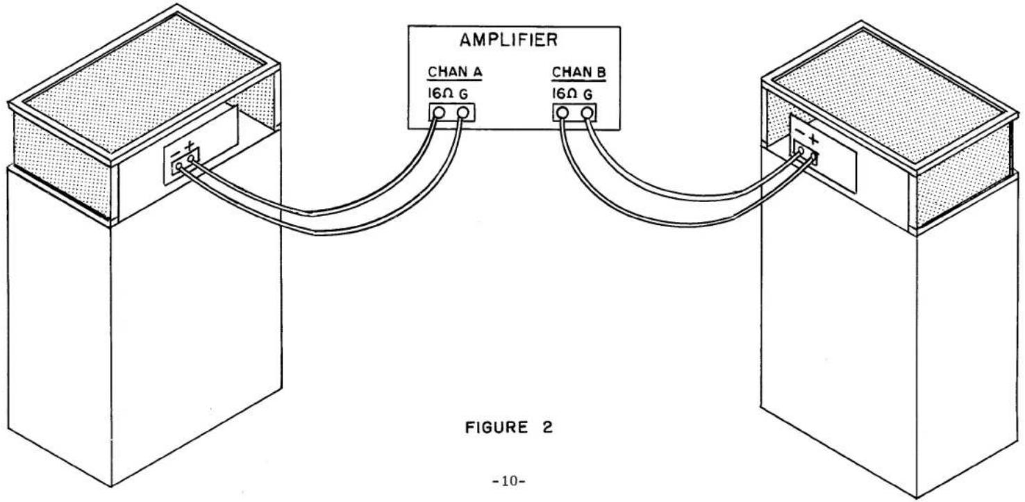
Most any type of wire may be used to connect the speaker to the amplifier. The only consideration is that the gauge of wire used should be #18 or heavier. Two-conductor lamp cord (commonly called "Zip" cord) is quite satisfactory.
It is important that polarity (+ and -) be observed when connecting two or more speakers in a stereo installation, to assure proper phasing of the speakers. When the speakers are properly phased, the cones will move in unison, both moving forward during a specific segment of the driving signal, rather than one moving forward (creating a positive pressure wavefront) while the other moves backward (creating a negative pressure). To assure proper phasing, the "+" terminal of each speaker should be connected to the 16 ohm output terminal of the amplifier (as in Figure #2), while the "-" terminal is connected to the ground terminal of the amplifier.
USING THE CITATION X LOUDSPEAKERS FOR STEREO
Due to its wide dispersion of the complete frequency spectrum, the Citation X loudspeaker system is not bound by the usual rules of room placement and listening location set down for stereo listening over conventional loudspeaker systems.
The combination of direct and reflected radiation presented to the listener prevents unnatural focusing of the sound source, and gives instead an area source for generation of the music. The normal tendency for more than one musical instrument to occupy the same point in space is completely absent, thus minimizing what we have come to describe as "Spatial Distortion" in musical reproduction.
No set rules can be propounded for determining the optimum loudspeaker placement and a certain amount of experimenting on your own part may well be rewarding. A shift of as little as 6 inches in a loudspeaker position can make a surprisingly large change in the sound in the room.
Our experience with a large variety of custom installations in homes, studios, and auditoriums has given us a number of basic configurations that work well.
- SMALL ROOM—TWO SPEAKER ARRANGEMENT
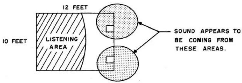
FIGURE 1
Here it is desirable to increase the listening depth of the room. Lateral spread is not as important as moving away from the orchestra back in the hall. This is accomplished by placing the speakers along the wall as in Figure 1. The sound appears to originate from the dotted area, which creates the impression of extending beyond the dimensions of the room.
- NORMAL ROOM—TWO SPEAKER ARRANGEMENT
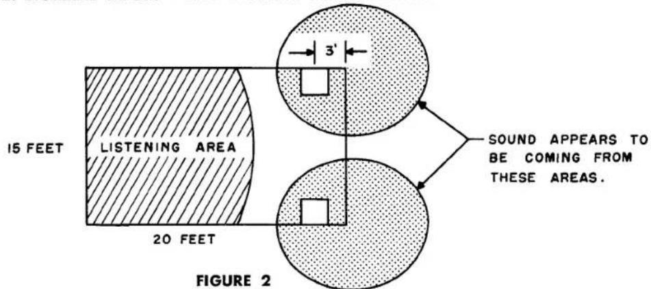
Here the room is large enough to listen in depth but more lateral spread is desirable.
Where too great a spread is obtained on any given program material, cross feeding via the blend control (available on most good preamplifiers) will fill in the middle and reduce separation to any desired degree.
- LONG NARROW ROOM—TWO SPEAKER ARRANGEMENT
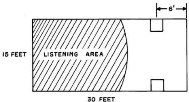
FIGURE 3
This room provides ample depth but lateral separation is needed. Adjust wall position to suit.
- SQUARE ROOM—TWO SPEAKER ARRANGEMENT
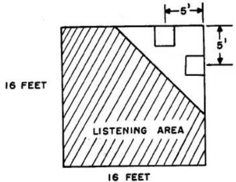
FIGURE 4
An extremely effective presentation of spacious stereo sound is produced by this arrangement. Changing the position of the speakers along the wall will vary the spread and depth.
5. IRREGULAR SHAPED ROOMS
Rooms with irregular shapes generally lend themselves to the same treatment as outlined above.
6. LARGER ROOMS, STUDIO, ETC.
Larger rooms, studios, auditoriums and more stubborn irregularly shaped rooms are best handled with a three speaker arrangement. In fact, our experience has shown the three speaker setup to out shine the two in every way except
cost and complexity. The extra degree of spatial control produces breathtaking realism with a wide variety of program source material.
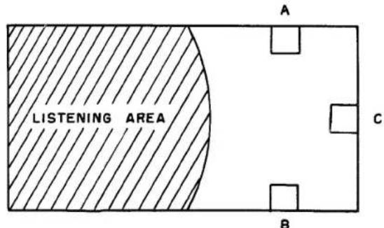
FIGURE 5
The center channel speaker is fed by a separate amplifier providing a 50-50 mix of the A and B signals with its own level control. Overall level is set and balanced with the A and B channel controls. As the center channel control is advanced a point is reached where every instrument in the orchestra seems to drop into place and the listener moves right into the concert hall with the music.
Monophonic listening to the two or three speaker setup (also called ambiphonic) is entirely satisfactory and in some cases can hardly be distinguished from stereo.
ACOUSTIC BALANCE
The acoustic balance control in the rear of the loudspeaker gives a measure of control to obtain correct musical balance between highs and lows in the listening room. Additional variation can be obtained, if needed, by controlling the wall surface around the loudspeaker. A hard painted plaster wall gives a bright sound. A wall paper softens somewhat, and a fabric drape softens the sound even further.
Our own preference in listening rooms is one softened by wall paper, but not dulled by too much absorption of high frequencies. Care should be used in applying sound absorbent material as it it usually more effective at the higher frequencies and can by over-absorption, accentuate the low frequency resonances (standing waves) produced by the dimensions of the room itself.
A good measure of satisfactory acoustics for good musical reproduction is conversation. In any good listening room it is possible to talk with another person in any part of the room without projecting ones voice, or having to raise it either in pitch or level. The room should not color a voice with extra chestiness or echo, nor thin it out.
PARTS LIST
| DESCRIPTION | QUANTITY PER KIT | PART NUMBER |
| Cabinet | 1 | W3944818 |
| Top Cover | 1 | WCIT4936 |
| Drive Assembly | 1 | SP3944976 |
| Flexible Seal | 1 | P3944939 |
| Back Plate | 1 | P3944975 |
| Control Panel | 1 | B3945067 |
| Coil | 1 | GL3945057 |
| Stubby Screwdriver | 1 | ZCOM5058 |
| Guide Block | 2 | Z3935097 |
Check the hardware card in the following sequence. Do not remove the plastic bags from the card. They will be removed as they are needed for construction
HARDWARE CARD #L3945068
| Fuse Block | 1 | ST3944957 |
| #6-32 x 5/8" Flat Heat Machine Screw | 2 | KH632-10SN |
| #6 Internal Tooth Lockwasher | 2 | KL6-SC |
| #6-32 Hex Nut | 2 | KN632-SC |
| Speaker Terminal Block | 1 | STCOM5070 |
| #6-32 x 3/4" Round Head Machine Screw | 4 | KR632-12SN |
| #6 Internal Tooth Lockwasher | 4 | KL6-SC |
| #6-32 Hex Nut | 4 | KN632-SC |
| Acoustic Balance Control | 1 | RV3945055 |
| #3/8 Internal Tooth Lockwasher | 1 | KL18-SC |
| #3/8-32 Hex Nut | 1 | KN1832-SC |
| #1/4-20 x 2" Binding Head Machine Screw | 1 | KM1420-32BN |
| #1/4 Flatwasher | 1 | KW14-SC |
| Masonite Washer | 1 | Z3945071 |
| #1/4 External Tooth Lockwasher | 1 | KX14-SC |
| #1/4-20 Hex Nut | 1 | KN1420-SC |
| Terminal Lug | 6 | STCOM4977 |
| DESCRIPTION | QUANTITY PER KIT | PART NUMBER |
| Bare Wire | 6" | WCOM4933 |
| #18 Stranded Wire (Black) | 24" | WIRE5041-0 |
| #18 Stranded Wire (Brown) | 30" | WIRE5041-1 |
| #18 Stranded Wire (White) | 6" | WIRE5041-9 |
| Fuse, 1 1/2 Amp 3 AG | 2 | ZCOM2953 |
| #10-32 x 3/4" Binding Head Machine Screw | 4 | KM1032-12SN |
| #10 Flatwasher | 4 | KW10-SC |
| #7 x 1 1/4 Flat Head Wood Screw | 12 | VP7-20SN |
| Citation X Name Plate | 1 | B3944945 |
| Escutcheon Pin | 4 | STCOM4971 |
MISCELLANEOUS
| Name Plate Mounting Template | 1 | L3944996 |
| Serial Number Notice Sheet | 1 | L3945014 |
| Warranty Card | 1 | LCOM4824 |
| Assembly and Operation Manual | 1 | L3944978 |
| Citation Sound Brochure | 1 | LCIT4723 |
This completes the parts list. When ordering replacement parts, be sure to specify the number listed in the "Part Number" column.
- ASSEMBLY
- OPERATION
- MANUAL
- CITATION X
- ASSEMBLY & OPERATION MANUAL
- INTRODUCTION
- SPECIFICATIONS AND FEATURES
- DRIVER
- HORN
- SYSTEM
- UNPACKING
- WARRANTY OF HARMAN-KARDON CITATION X
- SERVICE POLICY
- TOOLS REQUIRED
- ASSEMBLY PROCEDURE
- CONTROL PANEL ASSEMBLY
- STEP #
- CONTROL PANEL WIRING
- SEE FIGURE C, REAR VIEW.
- WIRING OF THE DRIVE UNIT
- SEE FIGURE D.
- DRIVE UNIT AND HIGH FREQUENCY STABILIZER, ASSEMBLY
- SEE FIGURE E.
- SEE PICTORIAL 2, FIGURE A.
- SEE FIGURE B
- SEE FIGURE C.
- NOTE
- CONNECTING THE SPEAKER TO THE AMPLIFIER
- USING THE CITATION X LOUDSPEAKERS FOR STEREO
- IRREGULAR SHAPED ROOMS
- LARGER ROOMS, STUDIO, ETC.
- ACOUSTIC BALANCE
Marke : HARMAN KARDON
Modell : Citation X
Kategorie : Lautsprecher