
CA240 - Empfänger HARMAN KARDON - Kostenlose Bedienungsanleitung
Finden Sie kostenlos die Bedienungsanleitung des Geräts CA240 HARMAN KARDON als PDF.


| Produkttyp | Hochleistungs-Car-Audio-Verstärker |
| Marke | Harman Kardon |
| Modell | CA240 |
| Ausgangsleistung (RMS) | 40 W pro Kanal an 4 Ω, 20–20.000 Hz 50 W pro Kanal an 2 Ω, 20–20.000 Hz 100 W gebrückt Mono an 4 Ω, 20–20.000 Hz |
| HCC (Hochmomentanstrom) | ±25 A |
| Klirrfaktor (THD) | ≤ 0,1 % (4 Ω) / ≤ 0,2 % (2 Ω) |
| Gegenkopplung | 25 dB |
| Leistungsbandbreite | 10 Hz – 100 kHz |
| Frequenzgang | 10 Hz – 100 kHz (+0/-3 dB) |
| Signal-Rausch-Abstand | 80 dB |
| Eingangsempfindlichkeit | 0,25 V – 3 V (einstellbar) |
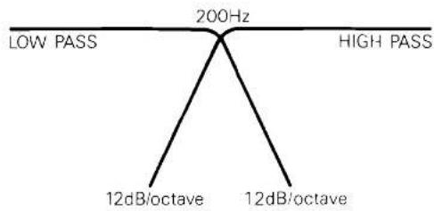
| Aktive Frequenzweiche | Hochpass: 200 Hz, 12 dB/Oktave Tiefpass: 200 Hz, 12 dB/Oktave |
| Stromversorgung | DC +13,8 V (11–16 V nutzbar), Masse negativ |
| Stromaufnahme (typisch) | Ruhestrom: 1,9 A Musik (4 Ω/Kanal): 4 A Musik (2 Ω/Kanal): 6 A Sinussignal (4 Ω/Kanal): 12 A Sinussignal (2 Ω/Kanal): 18 A |
| Abmessungen (B×H×T) | 310 × 68 × 203 mm (12-1/4" × 2-11/16" × 8") |
| Gewicht | 2,6 kg (5 lbs. 12 oz.) |
| Schutzschaltungen | Übertemperatur-, Verpolungs- und Kurzschlussschutz |
| Kühlung | Großer Kühlkörper, Konvektionskühlung |
| Farben | Schwarz |
| Mitgeliefertes Zubehör | Stromkabel (rot), Massekabel (schwarz), Fernbedienungskabel (orange), Auto-Sicherung (20 A) mit Halter, Montagebügel für Sicherungshalter, Kabelschuhe (6 Stk.), Montageschablone, Schrauben und Unterlegscheiben |
Häufig gestellte Fragen - CA240 HARMAN KARDON
Benutzerfragen zu CA240 HARMAN KARDON
0 Frage zu diesem Gerät. Beantworten Sie die, die Sie kennen, oder stellen Sie Ihre eigene.
Eine neue Frage zu diesem Gerät stellen
Laden Sie die Anleitung für Ihr Empfänger kostenlos im PDF-Format! Finden Sie Ihr Handbuch CA240 - HARMAN KARDON und nehmen Sie Ihr elektronisches Gerät wieder in die Hand. Auf dieser Seite sind alle Dokumente veröffentlicht, die für die Verwendung Ihres Geräts notwendig sind. CA240 von der Marke HARMAN KARDON.
BEDIENUNGSANLEITUNG CA240 HARMAN KARDON
harman/kardon
HIGH FIDELITY CAR AMPLIFIER
owner's manual mode d'emploi Bedienungsanleitung manuale di istruzioni Bruksanvisning gebruiksaanwijzing
CA240
SPECIFICATIONS
Congratulations on your purchase of a Harman Kardon CA240 High Fidelity Car Amplifier.
To fully understand the CA240's capability, please read this manual carefully and follow all of the instructions regarding its use and installation.
ACCESSORIES
- Power Cord (Red) (1 pc.)
- Ground Cord (Black) (1 pc.)
- Remote Cord (Orange) (1 pc.)
- Auto Fuse (20A) with Holder (1 set)
- Fuse Holder Mounting Bracket (1 pc.)
- Spade Lug with Tube (6 pcs.)
- Installation Template (1 pc.)
- Mounting Screws and Washers (1 set)
| Power Output, RMS | : 40 watts per channel into 4 Ohms, 20~20,000Hz |
| : 50 watts per channel into 2 Ohms, 20~20,000Hz | |
| : 100 watts bridged mono into 4 Ohms, 20~20,000Hz |
HCC (High Instantaneous: ±25A Current Capability)
THD (4 Ohms/2 Ohms) : No more than 0.1%/0.2%
Negative Feedback : 25dB
Power Bandwidth : 10Hz to 100,000Hz
Frequency Response : 10Hz to 100,000Hz +0, -3dB
Signal-to-Noise Ratio : 80dB
Input Sensitivity : 0.25V\~3V Adjustable
Active Crossover Characteristics
High Pass : 200Hz, 12dB/Octave
Low Pass : 200Hz, 12dB/Octave
Power Supply : DC +13.8V (11\~16V usable), negative ground
Typical Input Current Requirements
At Idle : 1.9A
Full Power Music : 4A (4 Ohms/ch.)
Signal : 6A (2 Ohms/ch.)
Full Power Sine : 12A (4 Ohms/ch.)
Wave : 18A (2 Ohms/ch.)
Dimensions (W×H×D) : 12-1/4" × 2-11/16" × 8" (310×68×203 mm)
Weight : 5lbs. 12oz. (2.6kg)
All specifications and features subject to change without notice.
FEATURES
GENERAL INSTRUCTIONS
■ 25 Amperes of HCC (High Instantaneous Current Capability) maintains a wide dynamic range and low distortion when driving low impedance or reactive loads.
■ High Power Output of 40 watts per channel into 4 Ohms, 50 watts per channel into 2 Ohms and 100 watts bridged-mono into 4 Ohms.
■ Ultrawide Bandwidth is achieved by the use of inherently fast open-loop circuitry. This improves transient accuracy and phase linearity.
■ Low Negative Feedback
Highly linear circuitry produces low distortion with only 25dB of negative feedback. This further improves dynamic accuracy.
■ Discrete Component Audio Circuitry is used because it was found to be the only way to provide HCC, Ultrawide Bandwidth and Low Negative Feedback.
■ High Capacity Power Supply
Four large capacitors, four 80 watt switching transistors, and a sophisticated transformer coil design enable stable operating voltages even under high power conditions. This results in improved low frequency sound quality.
■ High Heat Dissipation Capability is provided by a large heatsink, efficient circuitry and rugged circuit components.
■ Protection Circuitry assures reliability under high temperature, reverse-voltage and short-circuit conditions, without degrading the sound quality during normal high power operation.
■ Built-in Active Crossover and Bridged-mono features provide operating flexibility, system simplicity and added value.
- Be sure that metal objects or other foreign materials do not enter the unit. This can cause immediate trouble or reduce the unit's long-term reliability.
- It is natural for this unit to become warm while operating. It incorporates thermal protection circuitry to shut off the unit when operating abnormally.
- It is recommended that this unit be operated in a vehicle only while the engine (and electrical charging system) is running. At high power output, it typically draws about as much current as an automobile's headlights, and therefore can eventually discharge the battery.
● The speaker output terminals are protected from damage due to short-circuited speakers or speaker wires. When this protection circuitry is momentarily activated, the power output is muted for several seconds and is then restored. When the terminals are continuously short-circuited, the power output will remain muted. Should the latter occur, shut off the unit and check the speakers and speaker wires. - The heat generated by this amplifier is dissipated into the air by the entire chassis. If it is covered, or becomes dirty so that the circulation of the air around it is reduced, the unit's ability to dissipate heat will also be reduced. Under most conditions, the heat dissipating capability of this unit is more than enough to provide uninterrupted operation. However, when full power is drawn in an already hot environment, any loss in heat dissipating capability is likely to result in activating the thermal protection circuits.
● The accessory fuse (with holder) to be connected on the red cord is a 20 ampere auto fuse. When replacing the fuse, be sure to use an identical 20 ampere (amber) auto fuse. - If your unit behaves abnormally, turn it off immediately and consult an authorized Harman Kardon Service Station.
INSTALLATION LOCATIONS
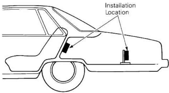
The locations shown in the above illustration are recommended for the CA240 installation. If you prefer another location, consult an authorized Harman Kardon Dealer or Service Station before making the installation.
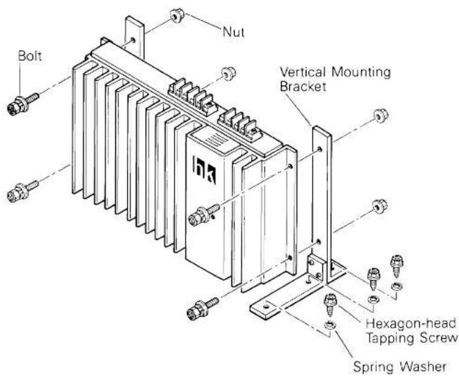
The recommended installation positions all result in vertical orientation of the heatsink fins. This provides the maximum heat dissipation capability. If possible, mount the CA240 chassis directly to a vertical or near-vertical surface, such as the inside wall behind the rear seat. If this is not possible, use the optional Vertical Mounting Bracket (BR1) to mount the CA240 to a horizontal surface, such as the trunk floor. The brackets permit vertical heatsink orientation when mounting to a horizontal surface.
In addition to vertical orientation, the recommended installation locations allow air to flow freely through the heatsink fins. This convection, or "chimney effect", provides maximum heat dissipation.
Horizontal heatsink orientation, such as when the unit is mounted under a seat or directly to the trunk floor, reduces heat dissipation and causes the unit to run hotter. At low temperatures (below 70^ F, 20^ C) or at low power levels, these positions may be acceptable. But at higher temperatures and/or power levels, these positions are likely to cause the thermal protection systems to activate.
INSTALLATION INSTRUCTIONS
Note 1: Drill undersized holes in the car chassis so that the 5mm tapping screws fit tightly. We recommend 3.5mm or 1/8 inch diameter holes.
Note 2: A template is enclosed so that the precise hole locations for the tapping screws can be easily determined.
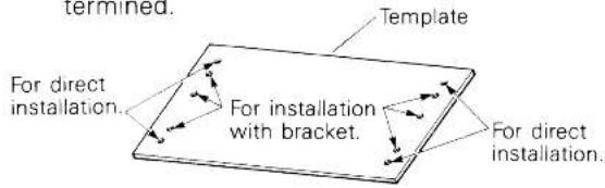
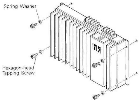
Directly Mounting to a Vertical Surface
Using the template, locate and drill 4 holes corresponding to those in the CA240 chassis. Securely mount the CA240 to the surface with the four 5mm hexagon-head tapping screws and spring washers.
Mounting to a Horizontal Surface with the Optional Brackets (BR1)
Using the template, locate and drill 6 holes corresponding to those in the short ends of the vertical mounting brackets. Mount the brackets to the surface with the six 5mm hexagon-head tapping screws and spring washers. Then mount the CA240 to the brackets using the four 5mm hexagon-head nuts and bolts.
CONFIGURATION
CONNECTIONS
Caution 1: The ignition key switch should be turned off before any connections are made to the car electrical system.
Caution 2: The last connection to be made should be to the positive terminal of the car battery.
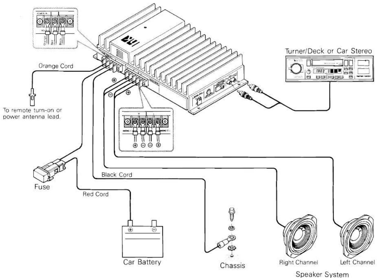
Connect the CA240 to the car electrical system and to the other components in the audio system as per the following instructions:
Remote
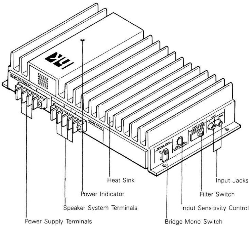
This terminal enables the power switch of the car stereo or tuner/deck to also turn on the CA240. Connect one end of the accessory orange cord to the appropriate lead (power amplifier remote) on the car stereo or tuner/deck and the other end to the remote terminal on the CA240 (cut the cord to the required length and attach the enclosed lug).
If a specific wire for this purpose is not provided on the tuner/deck, use the wire for controlling the power antenna. If that wire is already connected to the power antenna, the CA240 can be connected in addition.
Should no power antenna wire be provided, an SPST (Single-Pole, Single-Throw) switch and a pair of wires can be connected between the remote terminal and the +B terminal. When the switch is closed, the CA240 will turn on.
+B
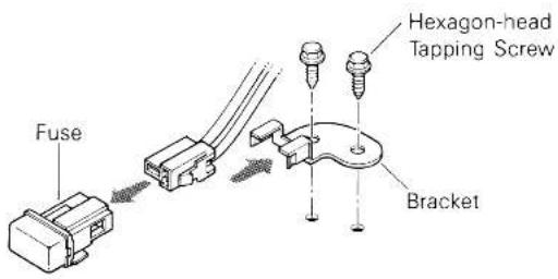
The +B terminal is the positive power input terminal. It should be connected to the positive (+) terminal of the car battery using the accessory red cord. It is good practice to connect the accessory fuse (with holder) on the red cord to protect the battery from a short circuit along the wire.
The fuse holder mounting bracket should be installed near the battery using two 5mm hexagon-head tapping screws. After inserting the fuse holder into the connector on the red cord, slide the fuse holder into the fuse holder mounting bracket to be fastened.
GND
This is the negative power input terminal. It should be connected directly to the car chassis using the accessory black cord. It is not necessary to connect this terminal to the negative battery terminal.
Speaker Systems
For a conventional stereo system with one or two speaker systems per channel, connect the speaker systems to these terminals. Be careful to connect the positive speaker terminals to the positive CA240 terminals. Do not connect the negative speaker terminals to the car chassis.
When one pair of speakers is used, each one may have an impedance in the range of 2\~8 Ohms and a power rating of at least 40 watts. If two pairs of speakers are used, each one may have an impedance in the range of 4\~8 Ohms and a power rating of at least 40 watts.
Input Jacks
These input jacks are for connection to the line (preamplifier) output jacks on the car stereo or tuner/deck. It is recommended that high quality shielded coaxial cables with tight-fitting RCA plugs be used for this connection.
If the car stereo has a built-in power amplifier and does not have line (preamplifier) output jacks, connect the speaker wires to these input jacks. Male phono plugs (not provided) are required.
Input Sensitivity Control
This control matches the input sensitivity of the CA240 to the output level of the car stereo or tuner/deck.
Set this control in the low (counterclockwise) range when the car stereo speaker wires are connected to the input jacks. Use a higher setting when connecting tuner/deck line (preamplifier) output jacks to the CA240 input jacks.
CONNECTIONS
BRIDGED-MONO OPERATION
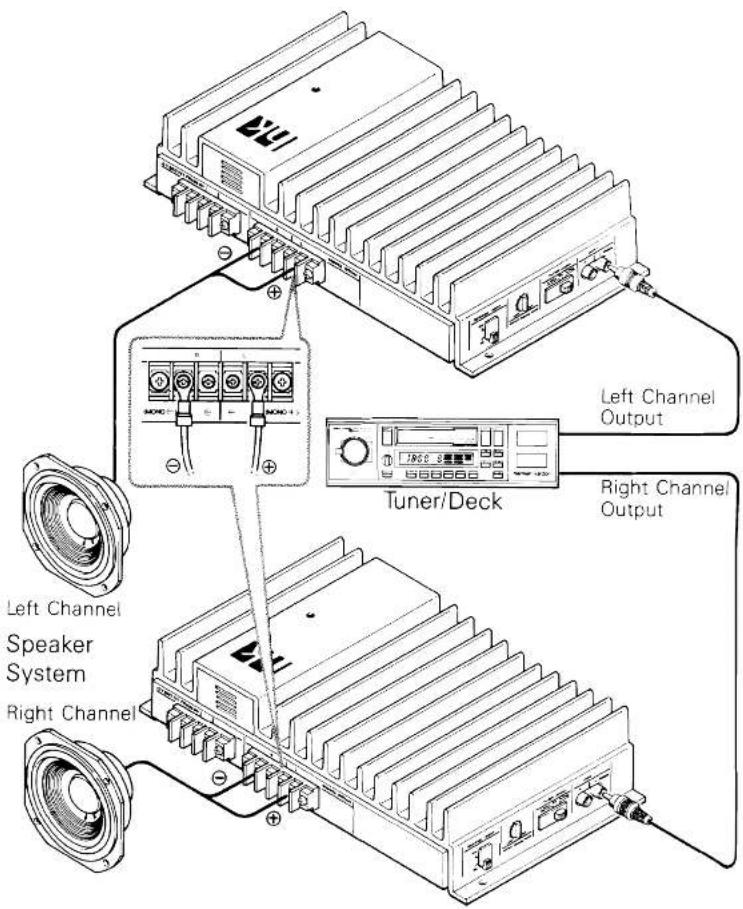
The CA240 is capable of operating as a 100 watt mono power amplifier when driving a 4 Ohm speaker system. When used this way, two units are required for a stereo system. The instructions for connecting a stereo system using two CA240's in the bridged-mono mode follow:
- Each amplifier will have one speaker system connected from the left channel positive (+) terminal to the right channel positive (+) terminal. The left channel positive terminal should be connected to the positive terminal of the speaker system. No connections are made to either of the CA240's negative speaker terminals.
- The input to each CA240 is made to its left channel input jack. In other words, the left channel output of the tuner/deck is connected to the left channel input jack of the CA240 driving the "left" speaker, and the right channel output of the tuner/deck is made to the left channel input jack of the CA240 driving the "right" speaker.
- The bridged-mono switch on each CA240 is placed in the "ON" position.
Note: Only one speaker system with an impedance of 4 Ohms, or two speakers with an impedance of 8 Ohms each, can be used in the bridged-mono mode. Also, only speaker systems with a sufficiently high power rating can be safely used.
USING THE HIGH PASS AND LOW PASS FILTERS
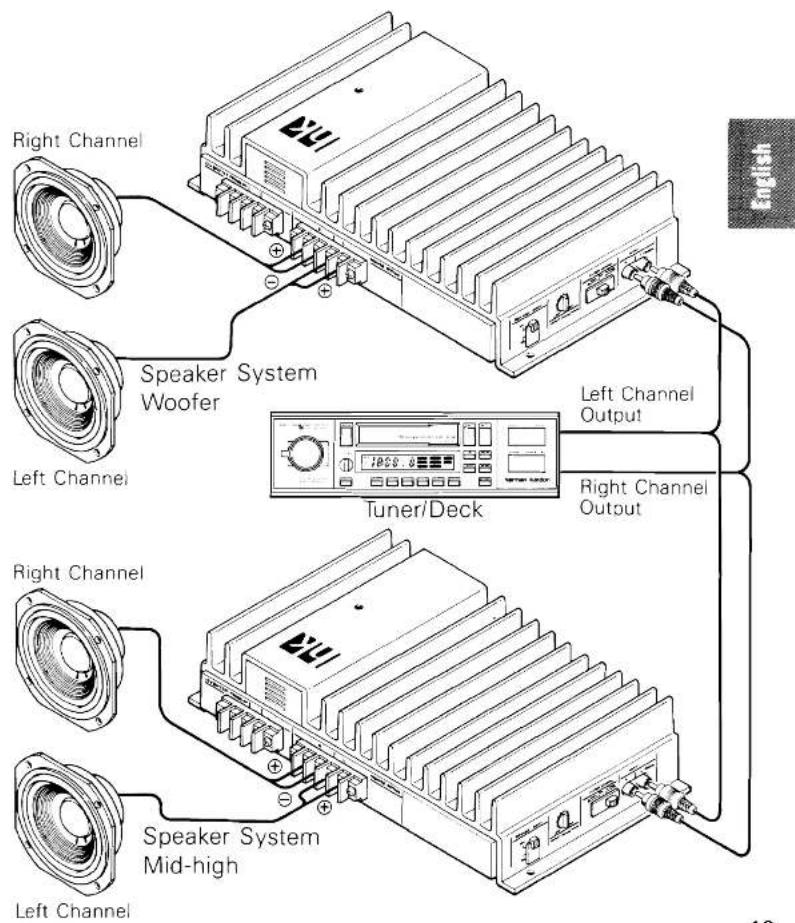
Two CA240's can be used with two woofers (low frequency speakers) and two mid-high (or full-range) speakers to make up an "active" system, both amplifiers being driven by the same tuner/deck. This type of system is connected as follows:
- Set the filter switch of one CA240 to the "L. PASS" position. Connect the woofers (low frequency speakers) to this amplifier.
- Set the filter switch of the other CA240 to the "H. PASS" position. Connect the mid-high (or full-range) speakers to this amplifier.
- Connect the left channel input jacks of each amplifier to the left channel output of the tuner/deck. Connect the right channel input jacks of each amplifier to the right channel output of the tuner/deck.
Note: If the tonal balance seems to be favoring either the high or low frequency range, try using different input sensitivity control positions to make the best balance. For example, if the sound is bass heavy, set the input sensitivity control for the "L. PASS" amplifier to the left (LOW) direction. This will reduce the signal to the woofers.
- CA240
- SPECIFICATIONS
- ACCESSORIES
- FEATURES
- GENERAL INSTRUCTIONS
- INSTALLATION LOCATIONS
- INSTALLATION INSTRUCTIONS
- Directly Mounting to a Vertical Surface
- Mounting to a Horizontal Surface with the Optional Brackets (BR1)
- CONFIGURATION
- CONNECTIONS
- Remote
- +B
- GND
- Speaker Systems
- Input Jacks
- Input Sensitivity Control
- BRIDGED-MONO OPERATION
- USING THE HIGH PASS AND LOW PASS FILTERS
Marke : HARMAN KARDON
Modell : CA240
Kategorie : Empfänger