
Petite - Holzofen JOTUL - Kostenlose Bedienungsanleitung
Finden Sie kostenlos die Bedienungsanleitung des Geräts Petite JOTUL als PDF.


| Produkttyp | Kaminofen |
| Marke | Jøtul |
| Modell | Petite |
| Material | Gusseisen mit Stahlverkleidung |
| Höhe | 70 cm |
| Breite | 45 cm |
| Tiefe | 40 cm |
| Gewicht | 60 kg |
| Heizleistung | 5 kW |
| Wirkungsgrad | 78 % |
| Brennstoff | Holz (Scheitholz) |
| Abgasrohrdurchmesser | 150 mm |
| Scheibe | Keramikglas, selbstreinigend |
| Verbrennungssystem | Nachverbrennung mit Luftzufuhr |
| Energieeffizienzklasse | A |
| CO-Emissionen | 0,1 % |
| Feinstaubemission | 40 mg/m³ |
| Abstand zu brennbaren Materialien | Mindestens 50 cm |
| Reinigung | Aschekasten entleerbar, Scheibe reinigen mit feuchtem Tuch |
| Zubehör | Anschluss an Schornstein, optional Warmluftauslass |
Häufig gestellte Fragen - Petite JOTUL
Benutzerfragen zu Petite JOTUL
0 Frage zu diesem Gerät. Beantworten Sie die, die Sie kennen, oder stellen Sie Ihre eigene.
Eine neue Frage zu diesem Gerät stellen
Laden Sie die Anleitung für Ihr Holzofen kostenlos im PDF-Format! Finden Sie Ihr Handbuch Petite - JOTUL und nehmen Sie Ihr elektronisches Gerät wieder in die Hand. Auf dieser Seite sind alle Dokumente veröffentlicht, die für die Verwendung Ihres Geräts notwendig sind. Petite von der Marke JOTUL.
BEDIENUNGSANLEITUNG Petite JOTUL
JOTUL

natural_image
Black-and-white sketch of a mechanical device with no visible text or symbolsPetite
Installation and Operation Instructions

SAFETY NOTICE: IF THIS SOLID FUEL ROOM HEATER IS NOT PROPERLY INSTALLED, A HOUSE FIRE MAY RESULT. FOR YOUR SAFETY, FOLLOW THE INSTALLATION DIRECTIONS. CONTACT LOCAL BUILDING OR FIRE OFFICIALS ABOUT RESTRICTIONS AND INSTALLATION INSPECTION REQUIREMENTS IN YOUR AREA.
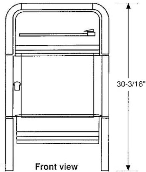
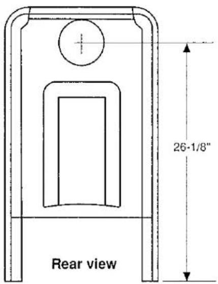
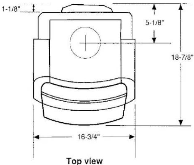
TABLE OF CONTENTS
-
GENERAL INFORMATION ...... 3
-
POSSIBLE HAZARDS TO AVOID WHEN USING THE J∅TUL PETITE .... 3
-
INSTALLATION....3
Safety Notice 3
Flue Exit Position 4
Assembling the Pieces 4
Plan Ahead 4
A. Chimney Connector (Stove Pipe) .... 4 Wall Pass-Through .... 5
B. Chimneys....6 Masonry Chimneys....6 Listed Metal Prefabricated Chimneys .. 7
C. Connection to the Chimney .... 7 Masonry Chimneys.... 7 Prefabricated Chimneys .... 8
D. Clearances to Combustibles....8 Floor Protection....8 Clearances to Adjacent Combustible Materials....8 Clearance Diagrams....9, 10 Alcove Installations....11
4. OPERATION
Wood Storage 11
Creosote and Soot Formation and the Need for Removal .... 12
Breaking in Your Stove 12
Controls....12 Front Door Latch....12 Primary Air Control....12 Start-Up Air Control....13
Building a Fire .... 13 Adjusting the Heat Output .... 13 Reloading .... 13 Ash Removal .... 14
- MAINTENANCE....14
General ....14 Glass Replacement....15 Glass Cleaning....15
1. General Information
The Owner's Manual describes the installation and operation of the Jøtul Petite non-catalytic wood heater. This heater meets the U.S. Environmental Protection Agency's emission limits for wood heaters sold after July 1, 1990. Under specific test conditions, this heater has shown heat output at rates ranging from 10,500 to 39,900 BTU's per hour.
When installing, operating, and maintaining your Jøtul Petite, follow the guidelines given in these instructions. Save these instructions, and make them available to anyone using the stove.
A number of areas of the U.S. require a building permit to install a solid-fuel burning appliance. NFPA 211 (National Fire Protection Association, Standard for Chimneys, Fireplaces, Vents, and Solid Fuel Burning Appliances) or similar codes may apply to the installation of solid fuel burning appliances in your area. Your Jøtul dealer has knowledge of your local codes and can provide assistance in making sure your installation is safe and legal. Also contact your insurance representative, building inspector, or fire officials to determine what regulations apply in your area.
The Jøtul Petite has been tested and listed to ANSI-UL 1482 by OMNI Environmental Services of Beaverton, Oregon.
2. Possible Hazards to Avoid When Using the Jøtul Petite Woodstove
Any use of fire in a house represents a certain danger. With intense overfiring, temperatures on the surface of the Petite can exceed 1000 degrees F. (536 degrees C).
Comply with the following guidelines:
- Never overfire the stove. If any part of the stove or chimney glows, you are overfiring, and a house fire or serious damage to the stove or chimney could result. Immediately close down the air control if you notice this condition.
- Teach children that the stove is hot and must not be touched.
- Never use gasoline, gasoline-type lantern fuel, kerosene, charcoal lighter fluid or similar liquids to start or "freshen up" a fire in this heater. They can ignite with explosive force, causing bodily injury or death. Keep all such liquids far away from the heater while it is in use.
- Never use the stove if there are combustible gases in the house. Certain cleaning fluids, adhe-
sives, and paints are a few examples of household products that can produce combustible gases. Remember, the operating woodstove is a source of "open flame".
- Avoid creating a "low pressure" condition in the room where the stove is operating, such as by operating an exhaust fan or a clothes dryer. A low pressure condition could cause poisonous gases to be drawn out of the stove into the room. You can prevent a low pressure condition by providing adequate outside combustion air within 24" of the stove.
- Never operate the Jøtul Petite if it has cracked or broken glass. Replace damaged glass only with the proper Petite glass panel available from your Jøtul dealer.
- Never burn trash of any kind in the stove.
- Keep combustible materials far away from the stove.
- Never modify the stove in any way.
- Do not dry clothes over the stove, since they could fall and ignite.
- Use only seasoned wood in your stove. Never use fireplace coal or synthetic logs that have not been approved for use in a wood stove.
• Always wear protective gloves when adding fuel to the fire. - This stove is not approved for use in mobile homes.
3. Installation
Safety Notice
IF THIS SOLID FUEL ROOM HEATER IS NOT PROPERLY INSTALLED A HOUSE FIRE MAY RESULT. FOR YOUR SAFETY, FOLLOW THE INSTALLATION DIRECTIONS. CONTACT LOCAL BUILDING OR FIRE OFFICIALS ABOUT RESTRICTIONS AND INSTALLATION INSPECTION REQUIREMENTS IN YOUR AREA.
Please read this entire manual before you install and use your new stove. Failure to follow instructions may result in property damage, bodily injury, or even death.
We recommend that you have your Petite installed by a professional installer of solid fuel room heaters.
Position the Optional Floor Plates
The Petite has two optional decorative floor plates that are available in blue-black enamel only. (Rear Plate, part no. 103210, Front Plate, part no. 103211).
Place the two plates beneath the stove and join them together. Then, position the legs of the Petite on the rear plate as shown in Figure 1.

PLEASE NOTE:
The floor plates are for decorative purposes only and are not a substitute for the floor protector specified on page 8 of this manual.
Choose One of Four Flue Exit Positions
Your stove may be vented from the top, rear, or side. "Knock-out" cover plates, that are lightly cast in place, seal these flue outlets. Once you have selected the flue exit position that suits your installation, remove the "knock-out" cover plate from that position by striking it in the center with a hammer. Note the specific installation requirements for the safe installation of each of these vent configurations.
PLEASE NOTE: Should you need to change your flue outlet position, an optional Flue Outlet Cover Plate Kit is available from your authorized Jøtul dealer. Order part no. 153189 for blue-black enamel or part no. 153190 for black painted.
Install the Optional Hot Plate (Blue-black enamel only; not for top exit installations)
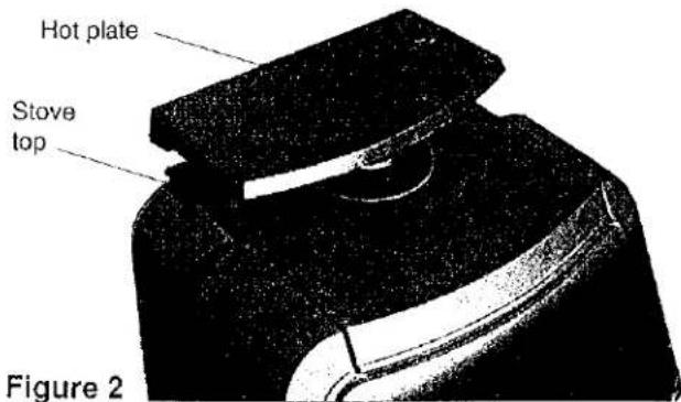
If your installation is not top-exiting, and you have purchased the optional hot plate, part no. 350249, place it at the rear of the stove top when the installation is complete. (Figure 2).
Plan Ahead
A safe stove installation involves several elements, including: (A) the chimney connector, (B) the chimney itself, (C) the connection between the chimney connector and chimney, and (D) protection of combustible materials in the vicinity of the stove. Each of these elements is equally important for a safe stove installation.
A. Chimney Connector (Stove Pipe)
Chimney connector is also sometimes called stove pipe or flue pipe, and it is used to connect the stove to the chimney. The chimney connector should be 6" diameter black steel, with a minimum 24 gauge thickness.
Do not use aluminum or galvanized steel pipe as a chimney connector. These materials cannot withstand the extreme temperatures of a wood fire and can give off toxic fumes when heated.
Matching enamel pipe is available for your Petite. Contact you Authorized Jøtul Dealer for more information.
Do not use chimney connector pipe as a chimney.
The factory-supplied adaptor (part no. 128566) must be used for fitting the stove's flue outlet hole to the chimney connector.
When installing this adaptor, apply the supplied self-adhesive gasket to the inside of the flue outlet flange. Then insert the small end of the adaptor in the flue outlet hole and secure the adaptor by bending the tabs with a hammer or pliers.
Chimney connector sections must be attached to the stove's flue exit adaptor and to each other with the crimped end toward the stove (Figure 3).

The space between the stove's flue exit adaptor and the chimney connector should be sealed with stove cement or an appropriately-sized piece of woodstove gasket material. This allows any small amounts of condensed creosote to run into the stove rather than onto the outside of the pipe or the stove top. All joints, including the adaptor to the flue exit, should be secured with three sheet metal screws to ensure that the sections will not separate.
In any side or rear flue-exit configuration, the stove's flue exit adaptor and any attached connector pipe must be supported by either wall pass-through brackets or ceiling pass-through support brackets.
For proper operation, the chimney connector should be as short as possible. Horizontal lengths should have an upward slope from the stove of 1/4" per foot. Avoid using more than two 90-degree elbows or total runs of pipe greater than 10'.
No part of the chimney connector may pass through an attic or roof space, closet or other concealed space, or through a floor or ceiling. Whenever possible, avoid passing the chimney connector through a combustible wall.
Wall Pass-Throughs
When your installation unavoidably requires that the chimney connector pass through a combustible wall to reach the chimney, extreme care must be taken. The National Fire Protection Association's publication NFPA 211, Standard for Chimneys, Fireplaces, Vents, and Solid Fuel Burning Appliances, permits four methods for passing through a combustible wall. Before beginning the installation, contact local building officials to make sure the proposed pass-through method meets local building code requirements.
A commonly used method to pass through a wall directly to a masonry chimney requires removal of all combustible material from at least 12" around the entire chimney connector. The space is then filled with at least 12" of brick around a fireclay liner. Be sure to locate it so that the top of the chimney connector will be at least 18" below the ceiling. To construct the brick pass-through, you will need an opening of 30" x 30" minimum. It will be necessary to cut wall studs, install headers, and construct a sill frame to maintain proper dimensions and to hold the weight of the brick. Minimum 3-1/2" (4" nominal) thick solid bricks are to be used. The fireclay liner (ASTM C35 or equivalent), minimum 5/8" wall thickness, must not penetrate into the chimney beyond the inner surface of the chimney flue liner and must be firmly cemented in place. If it is necessary to cut a hole in the chimney liner, use extreme care to keep it from shattering. Refractory mortar must be used at the junction to the chimney liner. See Figure 4.
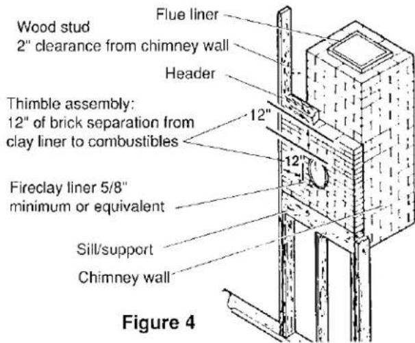
Figure 5 shows an approved installation that uses a section of listed solid fuel insulated factory-built chimney as a pass-through for the chimney connector.

Figure 5
The chimney section must have an inside diameter which is 2" larger than the chimney connector, have a minimum length of 12" and must have at least 1" of insulation thickness. The chimney section is installed with at least 2" of air space between the outer chimney wall and adjacent combustible materials.
Sheet steel support plates are used on both ends of the chimney section to keep the connector centered. The opening around the chimney section is closed on both sides of the wall with sheet steel plates and the chimney section is securely fastened to the plates. Fasteners used to support the chimney section should never penetrate the inner flue liner.
See NFPA-211 for other approved wall pass-through methods.
B. Chimneys
There are two types of chimneys suitable for the Petite: An approved masonry chimney, or a safety-listed residential-type building heating appliance chimney.
When selecting a chimney type and the location for the chimney in the house, keep this in mind: it is the chimney that makes the stove work, not the stove that makes the chimney work. This is because a chimney actually creates a suction, called draft, which pulls air through the stove
Several factors affect draft: the height, cross-sectional area, and temperature of the chimney, as well as the proximity of surrounding trees or buildings.
In general, a short masonry chimney on the exterior of a house will give the poorest performance. This is because it can be very difficult to warm up, and in extremely cold northern areas it may not work at all.
A tall masonry chimney inside the house is easier to keep warm and will work the best.
This guideline gives the necessary chimney requirements based on the national code (NFPA 211). However, many local codes differ from the national code to take into account climate, altitude, or other factors. It is important that you check with your local building officials to find out what codes apply in your area before constructing a chimney.
Masonry Chimneys
The minimum requirements for a properly constructed masonry chimney include the following:
- The foundation must be large enough to support the intended chimney without settling.
- The masonry wall of the chimney, if brick or modular block, must be a minimum of 4" nominal thickness. A mountain- or rubble-stone wall must be at least 12" thick.
- The chimney must have a fireclay flue liner (or equivalent) with a minimum thickness of 5/8" and must be installed with refractory mortar. There must be at least 1/2" air space between the flue liner and chimney wall.
- The preferred fireclay flue liner size has a nominal size of 8" x 8", and should not be larger than 8" x 12". If round fireclay liners are used, the inside diameter should be 6" and not larger than 8". If an existing chimney with larger tiles is used, it should be relined with an appropriate liner.
- No other appliance can be vented into the same flue.
- An airtight cleanout door should be located at the base of the chimney.
- A chimney inside the house must have at least 2" of clearance to the combustible structure. A chimney outside the house must have at least 1" clearance to the combustible structure. Fire stops must be installed at the spaces where the chimney passes through floors and/or ceilings (Figure 6).
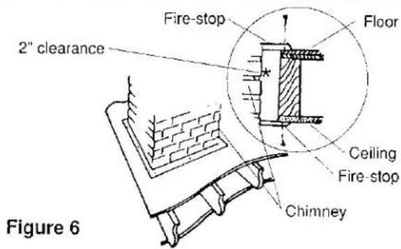
Remember that there must be air space around the chimney, and that insulation must be 2" or more from the chimney (Figure 7).

Figure 7
A chimney, whether masonry or prefabricated metal, must be the required height above the roof or other obstruction for safety and for proper draft operation. The requirement is that the chimney must be at least 3' higher than the highest point where it passes through the roof and at least 2' higher than the highest part of the roof or structure that is within 10' of the chimney, measured horizontally (Figure 8).

Chimneys shorter than 14' may not provide adequate draft. This could result in smoke spilling into the room from the door or joints in the stove or pipe. In addition, inadequate draft can cause backpuffing. A too-strong draft, on the other hand, can cause excessive temperatures and can shorten burn times. Excessive drafts can be corrected by having your dealer install a barometric damper set at 0.1" of water column. If you suspect you have a draft problem, consult your dealer.
Listed Metal Prefabricated Chimneys
When a metal prefabricated chimney is used, the manufacturer's installation instructions must be followed precisely. You must also purchase (from the same manufacturer) and install the ceiling support package or wall pass through, the "T" section package, the firestops (when needed), the insulation shield, the roof flashing, the chimney cap, etc. Maintain the proper clearance to the structure as recommended by the manufacturer. This clearance is usually a minimum of 2", although it may vary by manufacturer or for certain components.
There are basically two methods of metal chimney installation. One method is to install the chimney inside the residence through the ceiling and the roof (Figures 9, 10).
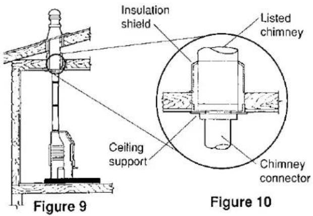
The other method is to install an exterior chimney that runs up the outside of the residence (Figures 11,12). The components illustrated may not look exactly like the system you purchase, but they demonstrate the basic components you will need for a proper and safe installation.

Figure 11
C. Connection to the Chimney
Masonry Chimneys
When connecting to a masonry chimney, the chimney connector must slide completely inside the chimney thimble (or breach) to the inner surface of flue liner. Make sure the connector does not protrude past the inside of the flue liner as that will reduce the flow area available for the smoke and ultimately cause problems with your chimney system. The chimney connector should be sealed into the thimble with refractory cement and the connector should also be mechanically fastened to the chimney. See Figure 13.

Prefabricated Chimneys
Always follow the chimney manufacturer's instructions and use all the components required by the manufacturer. Do not take shortcuts or use make-shift methods for securing the chimney connector to the chimney.
D. Clearances to Combustibles
Floor Protection
A bottom heat shield comes as standard equipment with the Petite and is required to be in place for all installations. In addition, the stove must be placed on a non-combustible floor protector that extends at least 8" beyond the sides and back of the stove and 16" in front of the stove. This will result in a minimum floor protector size of 33" wide X 41" deep (Figure 14a). The floor protector must also cover the area under any horizontal sections of chimney connector (stove pipe) and must extend at least 2" beyond either side of the pipe (Figure 14b).

Figure 14a
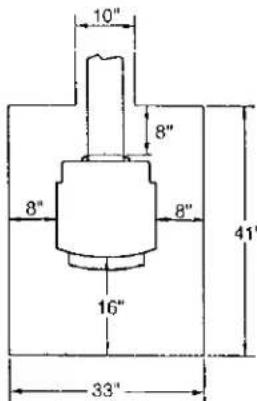
Figure 14b
The floor protector must contain two layers of 1/2 "thick USG Micore® Board with each layer having a K-value = .43 BTU-in. per ft²-hr.-°F. (or equivalent). A good method for making your floor protector is to cover the two layers of Micore® board with sheet metal or with listed non-combustible millboard or
listed non-combustible tile backer board (such as Wonderboard® or Durock®) and then finishing with a decorative layer consisting of any non-combustible material such as tile, slate or brick.
Never put any type of floor protection on top of carpeting.
Clearances to Adjacent Combustible Materials Figures 15a-j on pages 9 and 10 give the required clearances you must maintain from unprotected combustible materials or objects.
A combustible is anything that can burn, and in the case of stove installations, these combustibles may not be visible. If you are not sure of the combustible nature of any material in the vicinity of your planned stove installation, you should check with your local fire officials. Remember that "fire resistant" materials are considered combustible; they are difficult to ignite, but they will burn.
If you have recently purchased a home that has a stove hearth in it that you plan to use, it is extremely important that the entire system be examined for safety. Many older homes may have faulty chimneys, or previous owners may have covered combustible walls or studs with brick veneers. Heat is conducted readily through brick and could ignite unseen combustibles behind it.
Contact local building or fire officials about restrictions and installation requirements in your area.
Using Heat Shields to Reduce Clearances
The Jøtul Petite optional rear heat shield (part no. 950082) may be used in top-exiting, parallel installations to reduce clearance as shown in Figure 15b or in corner installations as shown in Figures 15e and 15g.
When utilizing a chimney connector heat shield to reduce connector pipe clearance, it must start 1" above the lowest exposed point on the connector pipe and extend vertically to a point 25" above the top surface of the stove. See Figures 15b, 15c, 15e, 15f, 15g, and 15h.
When utilizing wall protecting heat shields (wall protectors), they must be made from minimum 24 gauge galvanized sheet metal or equivalent and must be 48" X 48". They must start 1" from the floor and be spaced at least 1" from the walls. Figures 15c, 15f, 15g, 15h.

Parallel Installation, single wall connector, top vent. No rear stove heat shield, no connector pipe heat shield, no wall protection.

Corner Installation, single wall connector, top vent. No rear stove heat shield, no connector pipe heat shield, no wall protection.

Parallel Installation, single wall connector, top vent. With rear stove heat shield, and connector pipe heat shield. No wall protection.

Corner Installation, single wall connector, top vent. With rear stove heat shield and connector pipe heat shield. No wall protection.

Parallel Installation, single wall connector, top vent. No rear stove heat shield. With connector pipe heat shield and wall protection.

Corner Installation, single wall connector, top vent. No rear stove heat shield. With connector pipe heat shield and wall protection.
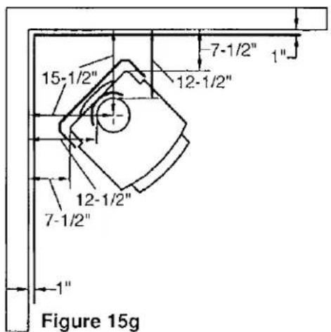
Corner Installation, single wall connector, top vent. With rear stove heat shield, connector pipe heat shield, and wall protection.

Corner Installation, single wall connector, rear vent to vertical connector. No rear stove heat shield. With connector pipe heat shield and wall protection.
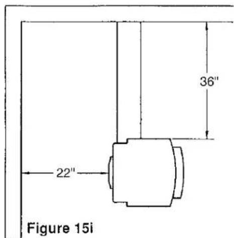
Parallel Installation, single wall connector, side vent. No rear stove heat shield, no connector pipe heat shield, no wall protection.

Parallel Installation, single wall connector, rear vent. No rear stove heat shield, no connector pipe heat shield, no wall protection.
Alcove Installations
When installed with single wall connector pipe with a connector pipe heat shield and with wall protection, the Jøtul Petite can be placed in an alcove that has a minimum height of 96" ^1 and a maximum depth of 48" (Figure 16a), and that has a minimum width of 49" (Figure 16b). The clearances for this installation are shown in Figure 16b.
(Note: ^1 See NFPA 211 for ceiling clearance reductions with protection.)

Figures 16a and 16b: Alcove Installation, single wall connector, top vent.
No rear stove heat shield. With connector pipe heat shield and wall protection.
Wall Protection for Alcove Installations
The wall protector for an alcove must be noncombustible, such as a minimum 24 gauge galvanized steel or its equivalent, and must protect the rear wall and both side walls of the alcove. The wall protector must be elevated 1" from the floor to provide an air space and must be mounted to allow an air space of at least 1" between the shield and the combustible wall. The height of the wall protector, including the air space at the bottom, must be at least 49". (Figure 16a)
Both side walls and the rear wall must be protected by the wall protector. (Figure 16b) The side wall protection must extend the full depth of the alcove.
4. Operation
Before building a fire in your new stove, please read the following section carefully.
This stove is designed to burn natural wood only. Higher efficiencies and lower emissions generally result when burning air-dried seasoned hardwoods, as compared to softwoods or to green or freshly-cut hardwoods.
Do not burn:
• Coal • Treated or Painted Wood
• Garbage • Chemical Chimney Cleaners
- Cardboard - Colored Paper
- Solvents
- Trash
- Any synthetic fuel or logs that have not been approved for wood stoves.
Burning treated wood, garbage, solvents, colored paper, chemical chimney cleaners, or trash may result in release of toxic fumes.
Never use gasoline, gasoline-type lantern fuel, kerosene, charcoal lighter fluid, or similar liquids to start or "freshen up" a fire in this heater. Keep all such liquids far away from the heater while it is in use.
Wood Storage
When storing wood outside, it should be covered and stored off the ground to protect it from the elements. Make certain that the woodpile has good air circulation through it in order to promote drying to aid in the seasoning process.
To obtain the best performance from your stove, we recommend using seasoned hardwood that has been dried and stored under cover for at least one year. Burning unseasoned or wet wood causes the rapid development of creosote and reduces the heat value of the wood being burned.
Creosote and Soot Formation and the Need for Removal
When wood is burned slowly, it produces tar and other organic vapors which combine with expelled moisture to form creosote. These creosote vapors condense in the relatively cool chimney flue of a slow burning fire. The creosote that accumulates in the flue is highly flammable and is the fuel of chimney fires. To prevent a chimney fire, the creosote needs to be removed by sweeping the chimney and flue connector. The frequency of sweeping will depend on how you operate your stove, but it is important to inspect the flue after every two weeks of use. An accumulation of 1/4" or more on the sides of the flue or connector is considered hazardous and should be removed.
In the event that creosote in your chimney or flue connector ignites, the resulting fire is often accompanied by a roaring noise and a crackling sound as flakes of burned creosote break loose. If you suspect you are having a chimney fire, immediately close the draft regulator and make sure the stove door is closed. Call the fire department and get everyone safely out of the house.
Trying to extinguish the fire in the stove will not help. In fact, it can make the matter worse by allowing oxygen through the door, which then supports the fire in the chimney. When the roaring and crackling have stopped, you should resist the temptation to open the door and look at the fire. The fire may have suffocated, but could rekindle when you open the door. After a chimney fire, do not use your stove until the chimney and the flue connector have been cleaned and inspected to ensure that no damage has been sustained.
Breaking in Your Stove
A cast iron stove should be "broken in" gradually. Five consecutive small fires must be built in the stove prior to operating the stove continuously. Each fire should be a little larger than the previous one, and the last fire should be a full-sized load. Allow the stove to cool completely between fires.
It is normal for new painted stoves to emit a smell or even some smoke during the first few fires. This is caused by the seasoning of the high temperature paint, and the odor will diminish with each fire and eventually disappear. Opening a window or door near the stove will help provide additional ventilation and reduce the odor.
Controls
The Multi-Purpose Detachable Handle
The multi-purpose detachable handle enables you to operate all of the stove's controls without touching a hot part. Even so, stove gloves should be worn to protect your hands near a hot stove.
The slot of the multi-purpose handle fits the door latch, the air control, and the handle nub of the ash pan. The hole in the other end of the multi-purpose handle fits over the ash shaker/start-up air control rod.
Front Door Latch
The latch for the front door is conveniently located to the left of the door's center. To open the door, slide the multi-purpose handle onto the handle stub and rotate it a quarter-turn counterclockwise. To close, press the door firmly against the stove front and rotate the handle a quarter-turn clockwise to vertical. See Figure 17.
Door is closed when handle is vertical. To open, turn counterclockwise.

natural_image
Black and white photo of a cylindrical object with a pointed tip, possibly a mechanical or electronic component (no visible text or symbols)Figure 17
Primary Air Control
The sliding primary combustion air control (See Figure 18) is located on the front panel above the fuel loading door.

Figure 18
Sliding the control to the right increases the air supply and the heat output; sliding it to the left decreases the air supply and the heat output.
Slide the control fully to the right when first starting or reviving a fire, or when maximum heat is required. Position the control in the middle or left of the middle when less heat is needed and when longer burn times are desired. You will determine the best settings for your particular needs as you gain experience with your stove.
Start-Up Air Control
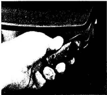
There is a special air supply for use during start-up. The ash shaker/start-up air control rod is located beneath the lower right corner of the ash lip. (Figure 19).
natural_image
Close-up of a hand gripping a dark object against a black background (no visible text or symbols)Pull = Open
Push = Close
Figure 19
This control is to be used only during the initial lighting and kindling of a fire. Do not open this control to freshen or accelerate the fire or during refueling. Opening this control can result in a dangerous overfiring condition which can damage the appliance or ignite surrounding combustible materials. Never leave the stove unattended while the control is open.
Building a Fire
A good fire will efficiently utilize your fuel, keep the glass in the door clean, keep emissions and creosote to an absolute minimum, require less work, and be very predictable.
A Good Foundation
Make sure that the primary combustion air control handle is fully to the right and that the start-up air control rod is in the open position (pulled out fully). Open the front door and cover the bottom of the stove with tightly crumpled newspaper. Criss-cross a generous double handful of dry kindling, such as split pieces of scrap lumber, on top of the paper. If you don't have scrap lumber, split some of your best dry wood down to finger-sized pieces and use that. Place three or four 1" - 2" split pieces of dry wood on top of the kindling.
Light the paper evenly across the front and close the door.
Continue to add 1" - 2" pieces of split dry wood until a healthy bed of glowing coals has formed.
You can now add three or four small-to-medium pieces of wood. Allow this wood to burn for several minutes. Once you are sure that the wood is burning well, close the start-up air (push rod fully in) and adjust the primary air control to set your desired heat output level and to maintain safe operating temperatures. Moving it to the right increases the heat; moving it too the left decreases the heat. Avoid operating the stove with the air control closed completely.
If the fire dies out, this cause is most likely either an insufficient bed of coals, reducing the air supply too soon, or using wood that is either too large or not dry enough.
Reloading
Reload the stove while it is still hot and there are plenty of hot coals to ignite the fresh fuel load. It is a good idea to include a smaller piece or two of wood at the base of the new load to help the stove recover more quickly to its operating temperature
Reloading Procedure
•Always wear stove gloves when tending your stove.
- Push the air control to the right to the full open position.
- Wait a few seconds and open the door.
- Use a stove shovel or similar tool to break up any remaining charcoal and to drag some live embers toward the front where combustion air enters.
- Load the fuel (Smaller pieces first).
- Close the door.
- Wait 5-10 minutes and adjust the air control to desired setting.
Note: If the charcoal bed present at reloading time is relatively deep (2" - 3") and your wood is well seasoned, it is possible to add the fresh fuel load, close the door and reset the air control for the desired heat output rate within 5 minutes.
Ash Removal
Ash removal will be required every day or two during normal operation, and is most easily done when the fire has burned down to coals.
Pull out and push in the ash shaker/start-up air control rod several times using your multipurpose handle. This should cause most of the ashes in the stove to fall into the ashpan. If necessary, open the front door and while the ash shaker control rod is pulled out, stir or push additional ash through the grate. It is not necessary to remove all the ash from the firebox. Remember to push the ash shaker control rod fully in when you are done de-ashing.
To remove the ashpan, open the front door with the multi-purpose handle and then insert the slot of the handle over the handle nub of the ashpan. (Figure 20) Slide the ashpan carefully from the stove.

natural_image
Black-and-white photo of a small object inside a circle on a dark background (no visible text or symbols)Figure 20b
Note that the ashpan has a special scoop design which ensures that stray ashes will not build up in the bottom of the stove. Be sure to keep the rear of the pan tipped up slightly so ashes do not fall out.
When removing ash from a stove that is in operation, close and latch the door before taking the ashes outside for safe disposal. It is always a good idea to wear heavy protective gloves while removing and disposing of the ashes from your stove.
Ashes should be placed in a metal container used exclusively for ashes, with a tight fitting lid. The closed container of ashes should be placed outdoors, well away from all combustible materials, pending final disposal. If the ashes are disposed of by burial in soil or otherwise dispersed, they should be retained in the closed container until all cinders have thoroughly cooled.
LEAVING THE DOOR OPEN OR THE ASH SHAKER CONTROL ROD IN THE PULLED OUT POSITION CAN RESULT IN A DANGEROUS OVERFIRING CONDITION WHICH CAN DAMAGE THE APPLIANCE OR IGNITE SURROUNDING COMBUSTIBLE MATERIALS.
WARNING: OPERATE YOUR PETITE ONLY WITH THE DOOR FULLY CLOSED. KEEP THE DOOR FULLY CLOSED EXCEPT WHEN LOADING FUEL OR REMOVING ASHES. A PARTIALLY OPEN DOOR MAY RESULT IN OVERFIRING.
5. Maintenance
General
At least once a year, perform a routine maintenance check. A good time to do this is when you are cleaning the chimney and the connector. You should clean the chimney and connector whenever accumulations of soot and creosote reach 1/4" thick, which may be several times a year, depending on how the stove is operated.
-
Thoroughly clean the entire stove. Brush all ash and soot out of the stove. It is better to brush out the ash and soot than to vacuum it out because soot particles are small enough to pass through most vacuum bags.
-
In a dark room, use a strong light to inspect the stove inside and out for cracks or leaks at corners and joints. Cracked parts should be replaced. Leaks at joints can be patched with stove furnace cement.
-
Check the door and window gaskets for tightness. To check the front door gasket, put a dollar bill halfway into the stove, close and latch the door, and try pulling the dollar out. If it can be removed easily, the seal is too loose. Check several spots around the door. To replace the gasket, scrape out all old gasket material and gasket cement. Spread a 1/8" bead of stove cement into the bottom of the groove and press in new gasket. Trim off any excess gasket length. The ends of the gasket should meet but not overlap.
The door requires approximately 61" of 1/4" diameter low density fiberglass woodstove gasket. The gasket between the glass panel and the door receives very little wear. The best indication that it needs to be replaced is streaks on the glass caused by air leaking around the gasket.
Glass Replacement
If the stove's glass is cracked or broken, you must replace it before operating your stove. Carefully remove any broken pieces. Replace the panel only with the correct Jøtul replacement glass, and do not use substitutes.
The glass can be replaced with the door still mounted to the stove:
- Carefully remove all broken glass, gasket material, screws, and glass retainers. See Figure 21.

- Clean off any residual gasket material from the door using a wire brush if necessary.
•The replacement gasket is 1/8" diameter low density fiberglass gasket and is self-adhesive.
Measure enough gasket to go from the upper right corner of the glass, down the right side, across the bottom and back up to the upper left corner and then back across to the starting point and then add about 2". (Approximately 49" of gasket.)
- Peel off about 12" of the self-adhesive backing strip. Starting in a corner, apply the gasket to the groove on the door, making sure that the adhesive is facing the door. Press the gasket firmly in place. Repeat peeling off more backing and applying until you reach your starting corner.
- Trim off any excess gasket length. It is important that the ends meet closely but not overlap.
- Center the replacement glass panel on the gasket and reinstall the glass retainers and screws.
It is extremely important that the retainers be tightened a small amount at a time and following a pattern similar to tightening the lug bolts on an automobile wheel. They should end up equally tightened and not over-tightened. Make sure that the glass panel stays centered in the opening and does not slip down. It may be necessary to re-tighten once again after the stove has been burned and the new gasket has been seated.
Glass Cleaning
From time to time, clean off the accumulated ash from the inside surfaces of the glass panels. If this fly ash is allowed to remain on the surface for extended periods, it could eventually cause the glass to become permanently etched and somewhat cloudy. Any creosote which might deposit on the glass will burn off during the next hot fire.
Never clean the glass while it is hot and never use any abrasive materials to clean the glass. Cool water and a soft cloth or paper towel are usually all that is required. Rinse thoroughly with clean water after washing and dry completely before burning your stove.
- JOTUL
- Petite
- TABLE OF CONTENTS
- OPERATION
- General Information
- Possible Hazards to Avoid When Using the Jøtul Petite Woodstove
- Installation
- Safety Notice
- Position the Optional Floor Plates
- Choose One of Four Flue Exit Positions
- Install the Optional Hot Plate (Blue-black enamel only; not for top exit installations)
- Plan Ahead
- Chimney Connector (Stove Pipe)
- Wall Pass-Throughs
- Chimneys
- Masonry Chimneys
- Listed Metal Prefabricated Chimneys
- Connection to the Chimney
- Prefabricated Chimneys
- Clearances to Combustibles
- Floor Protection
- Clearances to Adjacent Combustible Materials Figures 15a-j on pages 9 and 10 give the required clearances you must maintain from unprotected combustible materials or objects.
- Using Heat Shields to Reduce Clearances
- Alcove Installations
- Wall Protection for Alcove Installations
- Do not burn:
- Wood Storage
- Creosote and Soot Formation and the Need for Removal
- Breaking in Your Stove
- Controls
- The Multi-Purpose Detachable Handle
- Front Door Latch
- Primary Air Control
- Start-Up Air Control
- Building a Fire
- A Good Foundation
- Reloading
- Reloading Procedure
- Ash Removal
- Maintenance
- General
- Glass Replacement
- Glass Cleaning
Marke : JOTUL
Modell : Petite
Kategorie : Holzofen