
VT-7-46 - Beleuchtung V-TAC - Kostenlose Bedienungsanleitung
Finden Sie kostenlos die Bedienungsanleitung des Geräts VT-7-46 V-TAC als PDF.


| Produkttyp | LED-Linearleuchte für Aufputzmontage |
| Modell | VT-7-46 |
| Artikelnummern (SKU) | 20462, 20463, 20464, 20466, 20467, 21463 |
| Leistung | 40 W |
| Lichtstrom | 3400 Lumen |
| Abstrahlwinkel | 120° |
| Leistungsfaktor | 0,9 |
| Eingangsspannung | AC 200-240 V, 50 Hz |
| Abmessungen (L x B x H) | 1200 x 50 x 65 mm |
| Schutzart | Nur für Innenräume |
| Lichtquelle austauschbar | Nein – bei Defekt gesamte Leuchte ersetzen |
| Installation | Aufputzmontage mit mitgelieferten Bügeln |
| Verdrahtung | Gemäß Schaltplan: Phase (L), Neutralleiter (N), Schutzleider (PE) |
| Umgebungstemperatur | Nicht angegeben – typischerweise -20°C bis +40°C (Annahme) |
| Gehäusematerial | Aluminium und Kunststoff (Diffusor) |
| Montagezubehör | Befestigungsbügel, Dübel, Schrauben |
| Reinigung | Nur mit trockenem Tuch reinigen; keine feuchten Tücher oder Reinigungsmittel |
| Sicherheitshinweise | Vor der Installation Strom abschalten; nur durch qualifizierten Elektriker; Mindestabstand 0,2 m zu brennbaren Materialien |
| Zertifizierungen | CE, UKCA, RoHS |
| Garantie | Herstellergarantie – bei Fragen support@vtacexports.com |
| Marke | V-TAC |
Häufig gestellte Fragen - VT-7-46 V-TAC
Benutzerfragen zu VT-7-46 V-TAC
0 Frage zu diesem Gerät. Beantworten Sie die, die Sie kennen, oder stellen Sie Ihre eigene.
Eine neue Frage zu diesem Gerät stellen
Laden Sie die Anleitung für Ihr Beleuchtung kostenlos im PDF-Format! Finden Sie Ihr Handbuch VT-7-46 - V-TAC und nehmen Sie Ihr elektronisches Gerät wieder in die Hand. Auf dieser Seite sind alle Dokumente veröffentlicht, die für die Verwendung Ihres Geräts notwendig sind. VT-7-46 von der Marke V-TAC.
BEDIENUNGSANLEITUNG VT-7-46 V-TAC
V-TAC
Meaningful Innovation.
INSTRUCTION MANUAL
LED LINEAR LIGHT - SURFACE
TECHNICAL DATA
| MODEL | VT-7-46 |
| SKU | 20462, 20463, 2046420466, 20467, 21463 |
| POWER | 40W |
| LUMENS | 3400 |
| BEAM ANGLE | 120° |
| DF | 0.9 |
| INPUT POWER | AC: 200-240V, 50Hz |
| DIMENSION | 1200x50x65mm |
natural_image
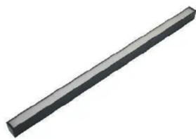
3D rendering of a long, straight gray rectangular object with no visible text or symbolsINTRODUCTION
Thank you for selecting and buying V-TAC product. V-TAC will serve you the best. Please read these instructions carefully before starting the installation and keep this manual handy for future reference. If you have any another query, please contact our dealer or local vendor from whom you have purchased the product. They are trained and ready to serve you at the best.
WARNING
- Please make sure to turn off the power before starting the installation.
- Installation must be performed by a qualified electrician
- Proper grounding should be ensured throughout the installation.
- The light source of this luminaire is not replaceable; when the light source reaches its end of life the whole
luminaire shall be replaced. - For Indoor use only
- Before installation, you must carefully check the integrity of the product and accessories
- When installed, products and flammable materials to ensure that at least 0.2m distance, lighting cannot be
installed in the zenith or heat wall, pay attention to low voltage and high voltage electrical wiring separately. - To ensure that the power cord has enough length, do not kink cables. Output cables should be laid separately and at a distance from other cables.

This marking indicates that this
product should not be disposed of with other household wastes.
Caution, risk of electric shock.

WARRANTY*

Illuminated

IN CASE OF ANY QUERY/ISSUE WITH THE PRODUCT PLEASE REACH OUT TO US AT SUPPORT@VTACEXPORTS.COM V-TAC HOUSE, KELPATRICK ROAD, SLOUGH, BERKSHIRE, SL1 6BW, UK.
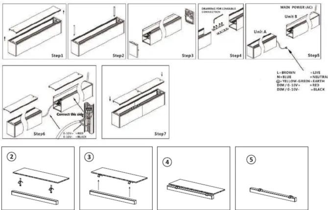
INSTALLATION DIAGRAM
INSTALLATION INSTRUCTIONS
- Switch off the power before starting the installation.
- Open end cap from any 1 side of the diffuser, slide the diffuser into the fitting. Close the end cap
by using screws. (Figure 1) - Choose the right position and drill 2 holes on the mounting surface. Then fix the brackets onto
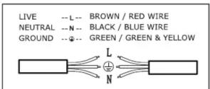
the mounting surface with help of expansion screws. (Figure 2 & 3) - Connect the wiring as per the wiring diagram, then install the light onto the bracket. (Figure 4).
- Switch on the power and test.
WIRING DIAGRAM
RoHS
CE
UK CA
Marke : V-TAC
Modell : VT-7-46
Kategorie : Beleuchtung