
FA-R - Messung Soler & Palau - Kostenlose Bedienungsanleitung
Finden Sie kostenlos die Bedienungsanleitung des Geräts FA-R Soler & Palau als PDF.


| Typ | Zentrifugalventilator, einseitig saugend |
| Bauart | Direktantrieb (Ausführung 4,5) oder Riemenantrieb (Ausführung 1,9,12) |
| Laufrad | Hochdruck-Vorwärtskrümmung, direkt auf Motorwelle oder auf Welle aufgekeilt |
| Gehäuse | Aus Stahlblech, schweißkonstruktion, mit KTL-Grundierung und Polyurethanlack RAL 7045, Gehäuse drehbar (LG/RD 0°-315°) |
| Motor | Drehstrom, 2/4/6-polig, 230/400V 50Hz (bis Größe 112), 400/690V 50Hz (größer), IP55, Klasse F, hohe Effizienz |
| Drehzahl | Bis zu 2930 min⁻¹ (Direktantrieb, je nach Modell) |
| Max. Fördermediumtemperatur | 100 °C (mit Kühlscheibe bis 220 °C bei Direktantrieb, bis 300 °C bei Riemenantrieb) |
| Max. Volumenstrom | Bis zu 1340 m³/h (Direktantrieb Modell 901/2), bis zu 1440 m³/h (Riemenantrieb Modell 901) |
| Schalldruckpegel (1 m) | 65–88 dB(A) (Direktantrieb, je nach Modell) |
| Gewicht (mit Motor) | 22–211 kg (Direktantrieb), 24–126 kg (Riemenantrieb, Ausführung 1) |
| Trägheitsmoment (Laufrad) | 0,04–2,73 kg·m² (Direktantrieb), 0,07–3,50 kg·m² (Riemenantrieb) |
| Anschlussflansche | Saugseite: Ø 140–180 mm (D1), Druckseite: Ø 50–80 mm (D6), mit Bohrungen |
| Schwingungsdämpfer | Serienmäßig vorgeschlagen: Typ AM20 bis AM50, je nach Modell |
| ATEX-Konformität | Auf Anfrage: explosionsgeschützte Ausführung nach 2014/34/EU (ATEX), Gas und Staub (Zone 2G/2D/3G/3D) |
| Zubehör | Flexible Verbindungen, Kondensatablass, Schwingungsdämpfer, Schutzgitter, Filter, Schalldämpfer, Drosselklappen, Ventile |
| Sonderausführungen | 60 Hz, andere RAL-Farben, feuerverzinkte Teile, korrosionsbeständig, verschleißfest, gasdicht, wärmegedämmt |
| Umgebungsbedingungen ATEX | -20°C bis +60°C, Umgebungsdruck 0,8–1,1 bar |
Häufig gestellte Fragen - FA-R Soler & Palau
Benutzerfragen zu FA-R Soler & Palau
0 Frage zu diesem Gerät. Beantworten Sie die, die Sie kennen, oder stellen Sie Ihre eigene.
Eine neue Frage zu diesem Gerät stellen
Laden Sie die Anleitung für Ihr Messung kostenlos im PDF-Format! Finden Sie Ihr Handbuch FA-R - Soler & Palau und nehmen Sie Ihr elektronisches Gerät wieder in die Hand. Auf dieser Seite sind alle Dokumente veröffentlicht, die für die Verwendung Ihres Geräts notwendig sind. FA-R von der Marke Soler & Palau.
BEDIENUNGSANLEITUNG FA-R Soler & Palau
FA-R


natural_image
Industrial machine component with curved frame and central hub (no visible text or symbols)Girante a pale positive Forward blades impeller

| QUADRO DI APPLICAZIONETABLE OF APPLICATIONS | |
| Tipologia del fluidoAir Type | Quantità di polvereDust quantity(mg/m3) |
| Aria polverosaDusty air | < 5000 |
Ventilatore centrifugo direttamente accoppiato. Prodotto in acciaio al carbonio protetto dalla corrosione tramite verniciatura per cataforesi con smalto poliuretanico bicomponente RAL 7045.
Esecuzioni standard
- Esecuzione 4: Accoppiamento diretto. Girante calettata direttamente sull'albero del motore B3 che è sostenuto dalla sedia. Temperatura massima dell'aria 100°C. Con ventolina di raffreddamento fino a 220°C.
- Esecuzione 5: Accoppiamento diretto. Girante calettata direttamente sull'albero del Motore B5 sostenuto da un disco fissato sul fianco cassa.
- Esecuzione 8: Accoppiamento a giunto. Girante calettata a sbalzo. Supporto e motore montati su sedia fuori dal circuito dell'aria. Temperatura massima dell'aria 100°C. Con ventolina di raffreddamento fino a 300°C.
Motori
Motori standard da 2 poli ad alta efficienza con alimentazione trifase 230/400V 50Hz fino alla taglia 112 e 400/690V 50Hz per le taglie superiori. Grado di protezione IP55, classe F.
Su richiesta
- Progettazione speciale con diversi materiali costruttivi.
- Versione a 60Hz.
- Verniciatura con RAL diversi dallo standard.
- Parti statiche del ventilatore zincate a caldo.
Direct drive, single inlet centrifugal fan. Manufactured from steel sheet protected with cataforesis primer + polyurethane paint finish RAL 7045.
Standard arrangement
- Arrangement 4: Direct drive. Impeller directly mounted on motor shaft. B3 motor is supported by the pedestal. Max air temperature 100^ . With cooling disk up to 220^ .
- Arrangement 5: Direct drive. Impeller directly mounted on motor shaft. B5 motor is fitted on casing sideplate.
- Arrangement 8: Flexible coupling. Overhung impeller. Support and motor mounted on a base outside the air stream. Max air temperature 100^ . With cooling disk up to 300^ .
Motors
2 pole, high efficiency, three-phase 230/400V 50Hz up to motor size 112 and 400/690V 50Hz for higher motors. IP55, Class F protection.
On request
• Manufactured from different materials.
- 60 Hz versions.
• Painted in different RAL colour.
• Hot dip galvanized static parts.
• Corrosion proof construction.
- Wear proof construction.
- Soluzioni con materiali resistenti alla corrosione.
- Versione con materiali antiusura.
- Motori elettrici per applicazioni speciali.
- Motori elettrici adatti per VSD.
- Possibilità di configurazione con svariati accessori tra cui: Giunti antivibranti, tappo di scarico, ammortizzatori, reti di protezione, filtro, silenziatore, regolatore di portata, valvole e serrande.
• Costruzioni a tenuta. - Coibentazione.
Versioni ATEX
Su richiesta ventilatori installati in luogo con pericolo di esplosione conformi alla direttiva 2014/34/UE (ATEX):
Temperatura ambiente tra -20°C/+60°C, pressione ambiente (assoluta) tra 0,8bar/1,1bar, in accordo con EN 14986.
Gas:
2G IIB T2-T3-T4*
26 IIB+H2 T2-T3-T4*
16 IIB T2-T3-T4*
12 IIB+H2 T2-T3-T4*
-
Polvere non conduttiva: 2D IIIB T125°C*-T135°C*-T195°C- T295°C
3D IIIB T125°C*-T135°C*-T195°C-T295°C -
Polvere conduttiva (con motore IP65 IIIC):
2D IIIC T125°C*-T135°C*-T195°C-T295°C
3D IIIC T125°C*-T135°C*-T195°C-T295°C
* Richiesta fattibilità tecnica.
• Motors for special applications.
• Motors suitable for VSD.
• Accessories: Flexible joints, casing drain, AV-mounts, protection nets, filter, silencer, inlet discharge governor, valves, dampers.
• Gas tight construction.
• Thermal insulation.
ATEX versions
On request, explosion proof version fans in accordance with 2014/34/UE (ATEX directive):
Ambient temperature -20°C to +60°C, ambient pressure (abs.) 0.8 bar to 1.1 bar according to EN 14986.
• Gas;
2G IIB T2-T3-T4*
2G 11B+H2 T2-T3-T4*
3G IIB T2-T3-T4*
3G IIB+H2 T2-T3-T4*
• Non-conductive dust:
2D IIIB T125°C*-T135°C*-T195°C-T295°C
3D IIIB T125°C*-T135°C*-T195°C-T295°C
• Conductive dust (compulsory IP65 IIIC motor);
2D IIIC T125°C*-T135°C*-T195°C-T295°C
3D IIIC T125°C*-T135°C*-T195°C-T295°C
* Requested technical feasibility
GIRANTE A PALE POSITIVE AD ALTA PRESSIONE - ACCOPIAMENTO DIRETTO HIGH PRESSURE FORWARD BLADES IMPELLER - DIRECT DRIVE

CARATTERISTICHE TECNICHE / TECHNICAL FEATURES
È essenziale verificare che le caratteristiche elettriche Itensione, intensità, frequenza, ecc.) di targa del motore siano compatibili con l'impianto elettrico di installazione.
Please, check that electrical features (voltage, current, frequency, etc.) are suitable with your installation.
| Modello Model | Taglia motore Motor size | Velocità Speed (r.p.m.) | Potenza motore Motor power (kW) | Intensità di corrente massima assorbita 400V Maximum absorbed current 400V (A) | Portata massima Maximum airflow (m3/h) | Nivel presión sonora a 1 m Sound pressure level at 1 m (dB(A)) ^(1) | Peso Weight (kg) ^(2) | Momento di inerzia Moment of inertia (kg·m2) ^(3) |
| 2 POLI / 2 POLE | ||||||||
| FA 311/2 R4A 63B2 2780 0,25 0,68 230 65 22 0,04 | ||||||||
| FA 351/2 R4A 71A2 2810 0,37 0,90 260 67 25 0,06 | ||||||||
| FA 401/2 R4A 71B2 2820 0,55 1,25 280 69 37 0,09 | ||||||||
| FA 451/2 R4A 80A2 2830 0,75 1,59 320 71 39 0,14 | ||||||||
| FA 501/2 R4A 80B2 2840 1,10 2,33 340 73 42 0,19 | ||||||||
| FA 561/2 R4A 90S2 2840 1,50 3,07 400 75 60 0,28 | ||||||||
| FA 632/2 R4A 90S2 2840 1,50 3,07 320 76 64 0,45 | ||||||||
| FA 631/2 R4A 90L2 2850 2,20 4,43 460 77 67 0,53 | ||||||||
| FA 712/2 R4A 100LA2 2900 3,00 5,77 470 79 94 0,68 | ||||||||
| FA 711/2 R4A 112M2 | 2910 4,00 7,50 640 80 | 101 0,88 | ||||||
| FA 802/2 R4A 112M2 | 2910 4,00 7,50 540 82 | 112 1,03 | ||||||
| FA 801/2 R4A 132SA2 2890 5,50 | 10,10 830 84 | 126 1,35 | ||||||
| FA 902/2 R4A | 132MB2 | 2900 | 9,20 | 16,60 | 940 | 86 | 153 | 2,20 |
| FA 901/2 R4A | 160MR2 | 2930 | 11,00 | 18,70 | 1,340 | 88 | 211 | 2,73 |
1 Misurata in premente / Measured with duct on discharge
Tolleranza di +3dB/A, misurata nel massimo punto di efficienza / Noise level tolerance +2 dB/A, measured in the maximum efficiency point
2 Con motore incluso e per gli orientamenti LG270 o RD270 / With motor included and for LG270 or RD270 position
^3 Momento di inerzia della girante / Impeller's moment of inertia
TEMPO DI AVVIAMENTO / STARTING TIME
| ModelloModel | kW | rpm | t (sec) |
| FA 311 R4A/RD270 - 63B2 | 0,25 | 2780 | 6 |
| FA 351 R4A/RD270 - 71A2 | 0,37 | 2810 | 6 |
| FA 401 R4A/RD270 - 71B2 | 0,55 | 2820 | 6 |
| FA 451 R4A/RD270 - 80A2 | 0,75 | 2830 | 10 |
| FA 501 R4A/RD270 - 80B2 | 1,1 | 2840 | 10 |
| FA 561 R4A/RD270 - 90S2 | 1,5 | 2840 | 10 |
| FA 632 R4A/RD270 - 90L2 | 2,2 | 2850 | 10 |
| FA 631 R4A/RD270 - 90L2 | 2,2 | 2850 | 10 |
| FA 712 R4A/RD270 - 100LA2 | 3 | 2900 | 14 |
| FA 712 R4A/RD270 - 100LA2* | 3,8 | 2900 | 10 |
| FA 711 R4A/RD270 - 112M2 | 4 | 2910 | 14 |
| FA 711 R4A/RD270 - 112M2* | 5,2 | 2910 | 10 |
| FA 802 R4A/RD270 - 112M2 | 4 | 2910 | 14 |
| FA 802 R4A/RD270 - 112M2* | 5,2 | 2910 | 10 |
| FA 801 R4A/RD270 - 132SA2 | 5,5 | 2890 | 14 |
| FA 801 R4A/RD270 - 132SA2* | 7 | 2900 | 10 |
| FA 902 R4A/RD270 - 132MB2 | 9 | 2900 | 16 |
| FA 902 R4A/RD270 - 132MB2* | 11,5 | 2900 | 11 |
| FA 901 R4A/RD270 - 160MR2 | 11 | 2930 | 16 |
| FA 901 R4A/RD270 - 160MR2* | 14 | 2930 | 11 |
* Motori con potenza superiore a quella di catalogo / Motors with power higher than in the catalogue
CURVA CARATTERISTICA (in premente) / PERFORMANCE CURVES (at outlet)
- Portata in m³/h.
- Psf: Pressione statica in Pa.
- Modello - Potenza del motore in kW.
- Esempio: 631 - 2,2
Modello - kW
- Air volume in m^3 / h .
- Psf: Static pressure in Pa.
- Model - Motor power in kW.
- Example: 631 - 2,2
Model - kW
2 poli - Modelli dal 311 al 631
2 pole - Models from 311 to 631

2 poli - Modelli dal 712 al 901
2 pole - Models from 712 to 901
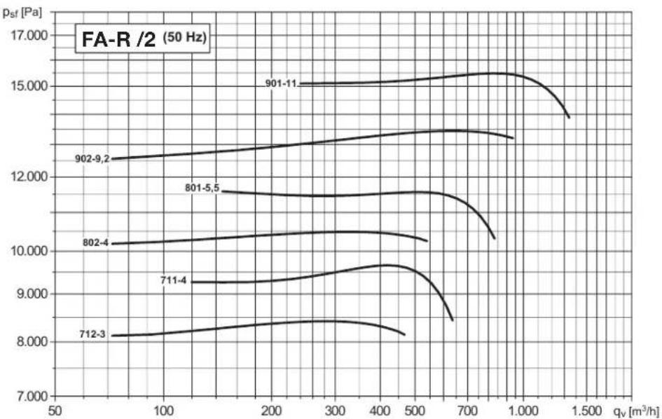
CURVA CARATTERISTICA (in aspirante) / PERFORMANCE CURVES (at inlet)
- Portata in m³/h.
- Psf: Pressione statica in Pa.
- Modello - Potenza del motore in kW.
- Esempio: 631 - 2,2
Modello - kW
- Air volume in m^3 / h .
- Psf: Static pressure in Pa.
- Model - Motor power in kW.
- Example: 631 - 2,2
Model - kW
2 poli - Modelli dal 311 al 631
2 pole - Models from 311 to 631

2 poli - Modelli dal 712 al 901
2 pole - Models from 712 to 901

line
| Sample | q_v [m³/h] | P_sf [Pa] | |--------|------------|-----------| | 712-3 | 100 | 7.2 | | 711-4 | 100 | 8.1 | | 802-4 | 100 | 9.5 | | 801-5.5| 100 | 10.2 | | 902-9.2| 200 | 11.8 | | 901-11 | 200 | 13.5 |DIMENSIONI (mm) / DIMENSIONS (mm)
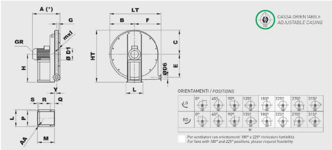
CASSA ORIENTABILE
ADJUSTABLE CASING
ORIENTAMENTI / POSITIONS
| LG | 0° | 45° | 90° | 135° | 180° | 225° | 270° | 315° |
| RD | 0° | 45° | 90° | 135° | 180° | 225° | 270° | 315° |
Per ventilatori con orientamenti 180° e 225° richiedere fattibilità For fans with 180° and 225° positions, please request feasibility
| Tipo Type | Ventilatore Fan | Base Base | |||||||||||||||||||
| Ventilatore Fan | Motore GR Motor GR | A* B | C∅ D1 | E F G H | HT mxl | Y LT∅ | D6 L P | M Q R S∅ AA | |||||||||||||
| FA 311/2 R4A | 63B2 | 285 | 245 | 240 | 182 | 220 | 270 | 35 | 280 | 520 | M6X16 | 31 | 515 | 54 | 206 | 184 | 184 | 45 | 125 | 14 | 10 |
| FA 351/2 R4A | 71A2 | 310 | 245 | 240 | 182 | 220 | 270 | 35 | 280 | 520 | M6X16 | 31 | 515 | 54 | 225 | 203 | 215 | 45 | 156 | 14 | 10 |
| FA 401/2 R4A | 71B2 | 310 | 325 | 315 | 182 | 300 | 350 | 35 | 355 | 670 | M6X16 | 31 | 675 | 54 | 225 | 203 | 215 | 45 | 156 | 14 | 10 |
| FA 451/2 R4A | 80A2 | 340 | 325 | 315 | 182 | 300 | 350 | 35 | 355 | 670 | M6X16 | 31 | 675 | 54 | 225 | 203 | 225 | 45 | 166 | 14 | 10 |
| FA 501/2 R4A | 80B2 | 340 | 325 | 315 | 182 | 300 | 350 | 35 | 355 | 670 | M6X16 | 31 | 675 | 54 | 225 | 203 | 225 | 45 | 166 | 14 | 10 |
| FA 561/2 R4A | 90S2 | 390 | 375 | 375 | 182 | 355 | 405 | 35 | 425 | 800 | M6X16 | 32 | 780 | 54 | 260 | 234 | 260 | 60 | 183 | 17 | 10 |
| FA 631/2 R4A | 90L2 | 390 | 375 | 375 | 182 | 355 | 405 | 35 | 425 | 800 | M6X16 | 32 | 780 | 54 | 260 | 234 | 260 | 60 | 183 | 17 | 10 |
| FA 632/2 R4A | 90S2 | 390 | 375 | 375 | 182 | 355 | 405 | 35 | 425 | 800 | M6X16 | 32 | 780 | 54 | 260 | 234 | 260 | 60 | 183 | 17 | 10 |
| FA 711/2 R4A | 112M2 | 500 | 425 | 425 | 200 | 400 | 455 | 41 | 475 | 900 | M6X16 | 38 | 880 | 66 | 324 | 289 | 310 | 23 | 264 | 23 | 12 |
| FA 712/2 R4A | 100LA2 | 450 | 425 | 425 | 200 | 400 | 455 | 41 | 475 | 900 | M6X16 | 38 | 880 | 66 | 324 | 289 | 295 | 23 | 249 | 23 | 12 |
| FA 801/2 R4A | 132SA2 | 580 | 475 | 480 | 200 | 450 | 505 | 41 | 530 | 1010 | M6X16 | 38 | 980 | 66 | 372 | 337 | 360 | 23 | 314 | 23 | 12 |
| FA 802/2 R4A | 112M2 | 500 | 475 | 480 | 200 | 450 | 505 | 41 | 530 | 1010 | M6X16 | 38 | 980 | 66 | 324 | 289 | 310 | 23 | 264 | 23 | 12 |
| FA 901/2 R4A | 160MR2 | 710 | 550 | 535 | 219 | 500 | 570 | 50 | 600 | 1135 | M6X16 | 47 | 1120 | 83 | 440 | 395 | 470 | 28 | 414 | 28 | 14 |
| FA 902/2 R4A | 132MB2 | 600 | 550 | 535 | 219 | 500 | 570 | 50 | 600 | 1135 | M6X16 | 47 | 1120 | 83 | 372 | 337 | 360 | 23 | 314 | 23 | 12 |
* In relazione al tipo di motore / Depending on motor type

| Modello Model | Flangia aspirante Inlet flange | |||||
| Tipo di flangia Flange type | ∅ D1 | ∅ D2 | ∅ D3 | ∅ AC | Fori Holes | |
| 311 ÷ 631 | 140 | 182 | 144 | 214 | 8 | 4 |
| 711 ÷ 801 | 160 | 200 | 164 | 234 | 8 | 4 |
| 901 | 180 | 219 | 184 | 254 | 8 | 4 |
| Modello Model | Flangia prementeOutlet flange | |||||
| Tipo di flangia Flange type | ∅D6 | ∅D4 | ∅D5 | ∅AF | Fori Holes | |
| 311 ÷ 631 | 50 | 54 | 84 | 104 | 8 | 4 |
| 711 ÷ 801 | 63 | 66 | 102 | 126 | 8 | 4 |
| 901 | 80 | 83 | 118 | 143 | 8 | 4 |
AMMORTIZZATORI / ANTI VIBRATION MOUNTS
| Ammortizzatori di serie / Suggested AV mounts | |
| Ventilatore / Fan | Esecuzione 4 / Arrangement 4 |
| 311 4 x AM 20 - 20x20 | |
| 351 4 x AM 20 - 20x20 | |
| 401 4 x AM 20 - 20x20 | |
| 451 4 x AM 20 - 20x20 | |
| 501 4 x AM 25 - 25x20 | |
| 561 4 x AM 25 - 25x20 | |
| 631/2 4 x AM 25 - 25x20 | |
| 711/2 4 x AM 30 - 30x30 | |
| 801/2 4 x AM 30 - 30x30 | |
| 901/2 4 x AM 40 - 40x30 | |


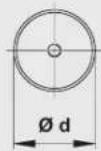
| Tipo Type | Carico per 4 ammortizzatoriLoad for 4 AV mounts(kg) | d h ∅ l | Peso Weight(kg) | ||
| AM20 11÷40 20 20 M6 15 0,02 | |||||
| AM25 41÷80 25 20 M6 18 0,03 | |||||
| AM30 81÷140 30 30 M8 20 0,05 | |||||
| AM40 | 141÷224 | 40 30 M8 23 0,10 |
FA-R


natural_image
Industrial machine with fan and impeller components mounted on a metal frame (no visible text or symbols)Girante a pale positive Forward blades impeller
| QUADRO DI APPLICAZIONETABLE OF APPLICATIONS | |
| Tipologia del fluidoAir Type | Quantità di polvereDust quantity(mg/m3) |
| Aria polverosaDusty air | < 5000 |
Ventilatore centrifugo con accoppiamento a trasmissione. Prodotto in acciaio al carbonio protetto dalla corrosione tramite verniciatura per cataforesi con smalto poliuretanico bicomponente RAL 7045.
Esecuzioni standard
- Esecuzione 1: Accoppiamento a cinghie. Girante calettata a sbalzo. Supporto montato su sede fuori dal circuito dell'aria. Albero nudo senza trasmissione e senza motore. Temperatura massima dell'aria 100°C. Con ventolina di raffreddamento fino a 300°C.
- Esecuzione 9: Accoppiamento a cinghie. Girante calettata a sbalzo. Supporto e trasmissione montati su sedi fuori dal circuito dell'aria. Motore sostenuto da una bandiera fissata sul fianco della sedia. Temperatura massima dell'aria 100°C. Con ventolina di raffreddamento fino a 300°C.
- Esecuzione 12: Accoppiamento a cinghie. Girante calettata a sbalzo. Supporto e trasmissione montati su sedi fuori dal circuito dell'aria. Motore e ventilatore sostenuti da un telaio di fondazione. Temperatura massima dell'aria 100°C. Con ventolina di raffreddamento fino a 300°C.
Motori
Motori standard da 2, 4, 6 poli ad alta efficienza con alimentazione trifase 230/400V 50Hz fino alla taglia 112 e 400/690V 50Hz per le taglie superiori. Grado di protezione IP55, classe F. La velocità del motore viene scelta in base al calcolo della trasmissione.
Belt drive, single inlet centrifugal fan. Manufactured from steel sheet protected with cataforesis primer + polyurethane paint finish RAL 7045.
Standard arrangement
- Arrangement 1: Belt drive. Overhung impeller. Support mounted on a base outside the air stream. Bare shaft without transmission and motor. Max air temperature 100^ . With cooling disk up to 300^ .
- Arrangement 9: Belt drive. Overhung impeller. Support and transmission mounted on a base outside the air stream. Motor fixed aside the support frame. Max air temperature 100^ . With cooling disk up to 300^ .
- Arrangement 12: Belt drive. Overhung impeller. Support and transmission mounted on a base outside the air stream. Motor and fan fitted on the base frame. Max air temperature 100^ . With cooling disk up to 300^ .
Motors
2, 4 or 6 pole, high efficiency (the rpm of each motor will be adapted according to the calculation for each drive), three-phase 230/400V 50Hz up to motor size 112 and 400/690V 50Hz for higher motors. IP55, Class F protection.
Su richiesta
- Progettazione speciale con diversi materiali costruttivi.
- Versione a 60Hz.
- Verniciatura con RAL diversi dallo standard.
- Parti statiche del ventilatore zincate a caldo.
- Soluzioni con materiali resistenti alla corrosione.
- Versione con materiali antiusura.
- Motori elettrici per applicazioni speciali.
- Motori elettrici adatti per VSD.
- Possibilità di configurazione con svariati accessori tra cui: Giunti antivibranti, tappo di scarico, ammortizzatori, reti di protezione, filtro, silenziatore, regolatore di portata, valvole e serrande.
• Costruzioni a tenuta.
• Coibentazione.
Versioni ATEX
Su richiesta ventilatori installati in luogo con pericolo di esplosione conformi alla direttiva 2014/34/UE (ATEX):
Temperatura ambiente tra -20°C/+60°C, pressione ambiente (assoluta) tra 0,8bar/1,1bar, in accordo con EN 14986.
• Gas
2G IIB T2-T3
23 IIB+H2 T2-T3
IIB T2-T3
96 IIB+H2 T2-T3
- Polvere non conduttiva: 2D IIIB T195°C-T295°C 3D IIIB T195°C-T295°C
- Polvere conduttiva (con motore IP65 IIIC):
2D IIIC T195°C-T295°C
3D IIIC T195°C-T295°C
On request
- Manufactured from different materials.
- 60 Hz versions.
- Painted in different RAL colour.
• Hot dip galvanized static parts.
• Corrosion proof construction. - Wear proof construction.
- Motors for special applications.
• Motors suitable for VSD.
• Accessories: Flexible joints, casing drain, AV-mounts, protection nets, filter, silencer, inlet discharge governor, valves, dampers.
• Gas tight construction.
• Thermal insulation.
ATEX versions
On request, explosion proof version fans in accordance with 2014/34/UE (ATEX directive):
Ambient temperature -20°C to +60°C, ambient pressure (abs.) 0.8 bar to 1.1 bar according to EN 14986.
Gas:
2G IIB T2-T3
2G IIB+H2 T2-T3
3G IIB T2-T3
3G IIB+H2 T2-T3
• Non-conductive dust:
2D III B T195°C-T295°C
3D III B T195°C-T295°C
- Conductive dust (compulsory IP65 IIIC motor):
2D IIIC T195°C-T295°C
3D IIIC T195°C-T295°C
GIRANTE A PALE POSITIVE AD ALTA PRESSIONE - ACCOPPIAMENTO A TRASMISSIONE HIGH PRESSURE FORWARD BLADES IMPELLER - BELT DRIVE

CARATTERISTICHE TECNICHE / TECHNICAL FEATURES
È essenziale verificare che le caratteristiche elettriche Itensione, intensità, frequenza, ecc.) di targa del motore siano compatibili con l'impianto elettrico di installazione.
Please, check that electrical features (voltage, current, frequency, etc.) are suitable with your installation.
| Modello Model | Portata massima Maximum airflow (m3/h) | Potenza motore máxima Maximum motor power (kW) | Peso Weight (kg)[1] | Momento di inerzia Moment of inertia (kg·m2)[2] |
| FA 351 R1A 470 1,5 24 0,07 | ||||
| FA 501 R1A 550 3,0 37 0,24 | ||||
| FA 631 R1A 640 5,5 61 0,63 | ||||
| FA 711 R1A 780 7,5 91 1,03 | ||||
| FA 801 R1A 970 11,0 104 1,57 | ||||
| FA 901 R1A 1.440 15,0 126 3,50 |
1 Per l'esecuzione 1 e orientamenti LG270 e RD270 / For arrangement 1 and LG270 or RD270 position
^2 Momento di inerzia della girante / Impeller's moment of inertia
SUPPORTI DI SERIE 1 / STANDARD SUPPORT 1
| ModelloModel | 351-501 631 711-801 901 | ||
| Tipo di supportoSupport type | ST 47 A19 ST 62 A24 ST 80 A28 ST 90 A38 |
Vedi informazioni addizionali alla fine del catalogo / See additional information at the end of the catalog
LIMITE GRANDEZZA MOTORE ESECUZIONE 9 / MOTOR SIZE LIMIT FOR ARRANGEMENT 9
| ModelloModel | 351-501 631 711-901 | ||
| Taglia motoreMotor size | ≤ 90 L2 ≤ 100 L2 ≤ 132 M2 |
CURVA CARATTERISTICA (in premente) / PERFORMANCE CURVES (at outlet)
- Ptot: Pressione totale in Pa.
- Ptot: Total pressure in Pa.

line
| qv [m³/s] | Ptot [Pa] | RPM | | --------- | --------- | ----- | | 0.007 | 1.000 | 2000 | | 0.01 | 1.200 | 2240 | | 0.02 | 1.400 | 2500 | | 0.03 | 1.600 | 2800 | | 0.04 | 1.800 | 3150 | | 0.05 | 2.000 | 3550 | | 0.06 | 2.200 | 4000 | | 0.07 | 2.400 | 4500 | | 0.08 | 2.600 | 5000 | | 0.1 | 2.800 | 5000 | | 0.11 | 3.000 | 5000 | | 0.12 | 3.200 | 5000 | | 0.13 | 3.400 | 5000 | | 0.14 | 3.600 | 5000 | | 30 | 1.200 | 2240 | | 4 | 1.400 | 2500 | | 5 | 1.600 | 2800 | | 7 | 1.800 | 3150 | | 14 | 2.200 | 3550 | | 21 | 2.600 | 4000 | | 31 | 3.200 | 4500 | | 44 | 3.600 | 5000 | | 55 | 4.200 | 555 | | 66 | 4.600 | 6 | | 77 | 5.200 | 6.5 | | 88 | 5.600 | 7 | | 99 | 6.2 | 7.5 | | 129 | 6.6 | 8 | | 199 | 7.2 | 8.5 | | 289 | 7.6 | 9 | | 389 | 8.2 | 9.5 | | 499 | 8.6 | 1 | | 699 | 9.2 | 1.5 | | Note: The data is already in CSV format as it is not available for all values from the original table to be extracted from the image file.
line
| qv [m³/s] | Ptot [Pa] | Max. RPM | | --------- | --------- | -------- | | 0.01 | 1.600 | 1800 | | 0.014 | 2.000 | 2000 | | 0.02 | 2.500 | 2240 | | 0.03 | 3.000 | 2500 | | 0.04 | 3.500 | 2800 | | 0.06 | 4.000 | 3150 | | 0.08 | 4.500 | 3550 | | 0.1 | 5.000 | 4000 | | 0.12 | 5.500 | 4500 | | 0.16 | 6.000 | 47% |CURVA CARATTERISTICA (in premente) / PERFORMANCE CURVES (at outlet)
- Ptot: Pressione totale in Pa.
- Ptot: Total pressure in Pa.
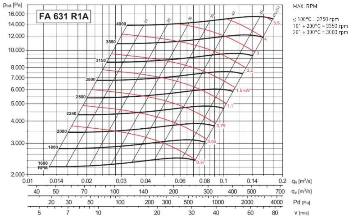

line
| qv [m³/s] | ptot [Pa] | Pd [Pa] | Velocity (rpm) | | --------- | --------- | ------- | -------------- | | 0.014 | 2.000 | 5 | 1400 | | 0.02 | 3.000 | 7 | 1600 | | 0.03 | 4.000 | 10 | 1800 | | 0.04 | 5.000 | 14 | 2000 | | 0.06 | 6.000 | 20 | 2240 | | 0.08 | 7.000 | 26 | 2500 | | 0.1 | 8.000 | 32 | 2800 | | 0.14 | 9.000 | 40 | 3150 | | 0.2 | 10.000 | 50 | 3550 | | 0.24 | 11.000 | 60 | | | 0.28 | 12.000 | 75 | | | 0.3 | 13.000 | | | | 0.35 | 14.000 | | | | 0.4 | 15.000 | | | | 0.45 | 16.000 | | | | 0.5 | 17.000 | | | | 0.55 | 18.000 | | | | 1 | 17.5 | | | | 2 | 17.2 | | | | 3 | 17.1 | | | | 4 | 17.0 | | | | 5 | 16.9 | | | | 6 | 16.8 | | | | 7 | 16.7 | | | | 8 | 16.6 | | | | 9 | 16.5 | | | | 10 | 16.4 | | | | 11 | 16.3 | | | | 12 | 16.2 | | | | 13 | 16.1 | | | | 14 | 16.0 | | | | 15 | 15.9 | | | | 16 | 15.8 | | | | 17 | 15.7 | | | | 18 | 15.6 | | | | 19 | 15.5 | | | | 2 | 15.4 | | | | Note: The data is already in CSV format with no additional formatting needed for the chart.CURVA CARATTERISTICA (in premente) / PERFORMANCE CURVES (at outlet)
- Ptot: Pressione totale in Pa.
- Ptot: Total pressure in Pa.


line
| qv [m³/s] | v [m/s] | Pd [Pa] | RPM | | --------- | ------- | ------- | --- | | 0.024 | 5 | 2.200 | 1250 | | 0.03 | 10 | 3.000 | 1400 | | 0.04 | 15 | 3.500 | 1600 | | 0.06 | 20 | 4.000 | 1800 | | 0.08 | 25 | 4.500 | 2000 | | 0.1 | 30 | 5.000 | 2240 | | 0.14 | 35 | 5.500 | 2500 | | 0.2 | 40 | 6.000 | 2800 | | 0.3 | 45 | 6.500 | 3150 | | 0.4 | 50 | 7.000 | 3150 | | 1.600 | 80 | 20.000 | 15 | | | | | 9.2 | | | | | 7.5 | | | | | 5.5 | | | | | 3 | | | | | 2.2 | | | | | 1.5 | MAX. RPM ≤100°C =3150 rpm, 101÷200°C =2800 rpm, 201÷300°C =2500 rpmDIMENSIONI (mm) / DIMENSIONS (mm)
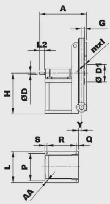


CASSA ORIENTABILE
ADJUSTABLE CASING
ESECUZIONE B
Con ventolina di raffreddamento richiedere disegno tecnico.
CONFIGURATION B
With cooling disk, request technical drawing.
ORIENTAMENTI / POSITIONS
| LG | 0° | 45° | 90° | 135° | 180° | 225° | 270° | 315° |
| RD | 0° | 45° | 90° | 135° | 180° | 225° | 270° | 315° |
Per ventilatori con orientamenti 180° e 225° richiedere fattibilità For fans with 180° and 225° positions, please request feasibility
| Tipo ventilatoreFan type | VentilatoreFan | Albero Shaft | Base Base | |||||||||||||||||||
| A | B | C | ∅ | D1 | E | F | G | H | HT | mxl | Y | LT | ∅ D6 | ∅ D | L2 | L | P | Q | R | S | ∅AA | |
| FA 351 R1A | 410 | 245 | 240 | 182 | 220 | 270 | 35 | 280 | 520 | M6X16 | 31 | 515 | 54 | 19 | ||||||||
| FA 501 R1A | 410 | 325 | 315 | 182 | 300 | 350 | 35 | 355 | 670 | M6X16 | 31 | 675 | 54 | 19 | ||||||||
| FA 631 R1A | 490 | 375 | 375 | 182 | 355 | 405 | 35 | 425 | 800 | M6X16 | 32 | 780 | 54 | 24 | ||||||||
| FA 711 R1A | 665 | 425 | 425 | 200 | 400 | 455 | 41 | 475 | 900 | M6X16 | 38 | 880 | 66 | 28 | ||||||||
| FA 801 R1A | 665 | 475 | 480 | 200 | 450 | 505 | 41 | 530 | 1010 | M6X16 | 38 | 980 | 66 | 28 | ||||||||
| FA 901 R1A | 720 | 550 | 535 | 219 | 500 | 570 | 50 | 600 | 1135 | M6X16 | 47 | 1120 | 83 | 38 | ||||||||
R12
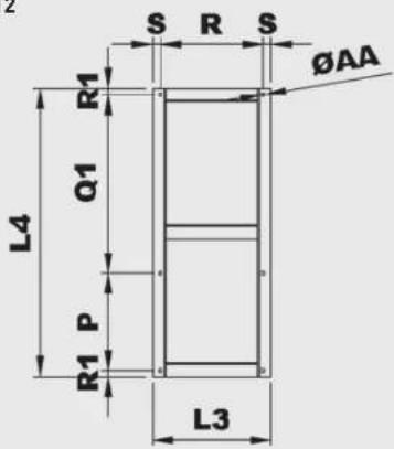
| Modello Model | Basamento esecuzione 12Base frame arrangement 12 | ||||||||
| P | L3 | L4 | Q1 | R | R1 | S | ∅ AA | Peso Weight (kg) | |
| 351 R12A | 228 | 275 | 750 | 495 | 241 | 13,5 | 17 | 10 | 10 |
| 501 R12A | 228 | 275 | 750 | 495 | 241 | 13,5 | 17 | 10 | 10 |
| 631 R12A | 288 | 349 | 850 | 526 | 303 | 18 | 23 | 12 | 14 |
| 711 R12A | 355 | 485 | 1000 | 600 | 429 | 22,5 | 28 | 14 | 20 |
| 801 R12A | 355 | 485 | 1000* | 600* | 429 | 22,5 | 28 | 14 | 20 |
| 901 R12A | 355 | 500 | 1180 | 780 | 444 | 22,5 | 28 | 14 | 23 |
* Per motori taglia 160, questa misura aumenta di 100 mm. For motor size 160, increase this dimension 100 mm

| Modello Model | Flangia aspirante Inlet flange | |||||
| Tipo di flangia Flange type | ∅ D1 | ∅ D2 | ∅ D3 | ∅ AC | Fori Holes | |
| 311 ÷ 631 | 140 | 182 | 144 | 214 | 8 | 4 |
| 711 ÷ 801 | 160 | 200 | 164 | 234 | 8 | 4 |
| 901 | 180 | 219 | 184 | 254 | 8 | 4 |

| Modello Model | Flangia prementeOutlet flange | |||||
| Tipo di flangia Flange type | ∅D6 | ∅D4 | ∅D5 | ∅AF | Fori Holes | |
| 311 ÷ 631 | 50 | 54 | 84 | 104 | 8 | 4 |
| 711 ÷ 801 | 63 | 66 | 102 | 126 | 8 | 4 |
| 901 | 80 | 83 | 118 | 143 | 8 | 4 |
AMMORTIZZATORI / ANTI VIBRATION MOUNTS
| Ammortizzatori di serie / Suggested AV mounts | ||
| Ventilatore / Fan | Esecuzione 9 / Arrangement 9 | Esecuzione 12 / Arrangement 12 |
| 311 4 x AM 20 - 20x20 4 x AM 25 - 25x20 | ||
| 351 4 x AM 20 - 20x20 4 x AM 25 - 25x20 | ||
| 401 4 x AM 25 - 25x20 4 x AM 30 - 30x30 | ||
| 451 4 x AM 25 - 25x20 4 x AM 30 - 30x30 | ||
| 501 4 x AM 25 - 25x20 4 x AM 30 - 30x30 | ||
| 561 4 x AM 30 - 30x30 4 x AM 30 - 30x30 | ||
| 631/2 4 x AM 30 - 30x30 4 x AM 30 - 30x30 | ||
| 711/2 4 x AM 40 - 40x30 4 x AM 40 - 40x30 | ||
| 801/2 4 x AM 40 - 40x30 4 x AM 40 - 40x30 | ||
| 901/2 4 x AM 50 - 50x40 4 x AM 50 - 50x40 | ||

| Tipo Type | Carico per 4 ammortizzatori Load for 4 AV mounts (kg) | d h ∅ l | Peso Weight (kg) | |||
| AM20 11÷40 20 20 M6 15 0,02 | ||||||
| AM25 41÷80 25 20 M6 18 0,03 | ||||||
| AM30 81÷140 30 30 M8 20 0,05 | ||||||
| AM40 | 141÷224 | 40 30 M8 23 0,10 | ||||
| AM50 | 225÷315 | 50 | 40 | M10 | 28 | 0,20 |
| AM75 | 316÷630 | 75 | 50 | M12 | 37 | 0,50 |



- FA-R
- Esecuzioni standard
- Motori
- Su richiesta
- Standard arrangement
- Motors
- On request
- Versioni ATEX
- ATEX versions
- GIRANTE A PALE POSITIVE AD ALTA PRESSIONE - ACCOPIAMENTO DIRETTO HIGH PRESSURE FORWARD BLADES IMPELLER - DIRECT DRIVE
- CARATTERISTICHE TECNICHE / TECHNICAL FEATURES
- CURVA CARATTERISTICA (in premente) / PERFORMANCE CURVES (at outlet)
- CURVA CARATTERISTICA (in aspirante) / PERFORMANCE CURVES (at inlet)
- GIRANTE A PALE POSITIVE AD ALTA PRESSIONE - ACCOPPIAMENTO A TRASMISSIONE HIGH PRESSURE FORWARD BLADES IMPELLER - BELT DRIVE
Marke : Soler & Palau
Modell : FA-R
Kategorie : Messung