
AutoReflex T2 - Nicht kategorisiert KONICA MINOLTA - Kostenlose Bedienungsanleitung
Finden Sie kostenlos die Bedienungsanleitung des Geräts AutoReflex T2 KONICA MINOLTA als PDF.


| Produkttyp | 35-mm-Spiegelreflexkamera (SLR) |
| Modell | Konica AutoReflex T2 (auch bekannt als New Autoreflex T) |
| Objektivanschluss | Konica AR-Bajonett |
| Verschluss | mechanischer Schlitzverschluss, vertikal ablaufend, 1 s – 1/1000 s + B |
| Belichtungsmessung | TTL-Offenblendmessung, CdS-Zelle, Messbereich abhängig von Filmempfindlichkeit |
| Filmempfindlichkeit | ASA 25 – 1600 (über Einstellrad) |
| Sucher | Pentaprisma, Einstellscheibe mit Mikroprismenring und Schnittbildindikator |
| Spiegel | Rückkehrender Spiegel, mechanisch gesteuert |
| Transport | manueller Filmtransport über Hebel, Rückspulkurbel |
| Selbstauslöser | mechanisch, ca. 10 Sekunden Verzögerung |
| Blitzsynchronisation | X-Synchronisation bei 1/125 s, M-Synchronisation bei allen Zeiten |
| Stromversorgung | eine Quecksilberbatterie (z. B. PX625) oder moderne Alternative |
| Gehäuse | Metallgehäuse mit schwarzer Ledergravur, kompakt und robust |
| Abmessungen | ca. 143 × 90 × 53 mm (ohne Objektiv) |
| Gewicht | ca. 620 g (nur Gehäuse) |
| Wartung | Verschlusszeiten und Messung regelmäßig überprüfen, Lagerung trocken und staubfrei |
| Ersatzteile | umfangreiche Ersatzteilliste in der Bedienungsanleitung, viele Teile noch erhältlich |
| Besonderheiten | exakte Mechanik, hochwertige Verarbeitung, automatische Belichtungssteuerung über Shutter-Priority (nicht im Standardmodell) |
Häufig gestellte Fragen - AutoReflex T2 KONICA MINOLTA
Benutzerfragen zu AutoReflex T2 KONICA MINOLTA
0 Frage zu diesem Gerät. Beantworten Sie die, die Sie kennen, oder stellen Sie Ihre eigene.
Eine neue Frage zu diesem Gerät stellen
Laden Sie die Anleitung für Ihr Nicht kategorisiert kostenlos im PDF-Format! Finden Sie Ihr Handbuch AutoReflex T2 - KONICA MINOLTA und nehmen Sie Ihr elektronisches Gerät wieder in die Hand. Auf dieser Seite sind alle Dokumente veröffentlicht, die für die Verwendung Ihres Geräts notwendig sind. AutoReflex T2 von der Marke KONICA MINOLTA.
BEDIENUNGSANLEITUNG AutoReflex T2 KONICA MINOLTA
KONICA New AUTOREFLEX T
Technical Illustration with parts list
分解透視図・部品リスト 専用工具図及びリスト
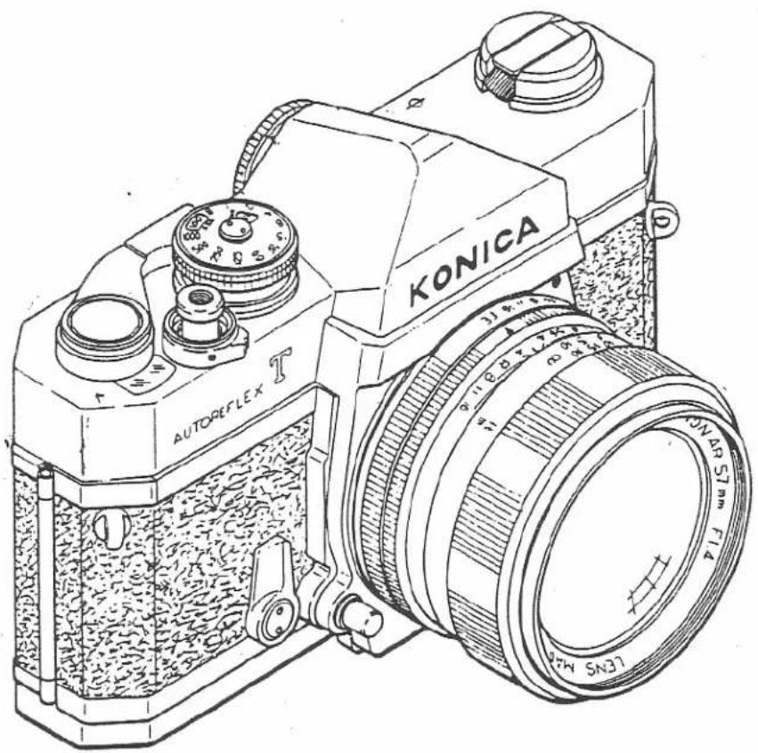
natural_image
Line drawing of a KONICA self-sensor camera with visible lens and control knobs (no text or symbols on body)HOW TO MAKE THE BEST USE OF THIS LIST
This list is to be utilized as a guide in disassembling and assembling KONICA NEW AUTOREFLEX T (FTA II in short) and also in ordering as for the supply of parts and ready-made assembled parts your require.
© For disassembling KONICA NEW AUTOREFLEX T
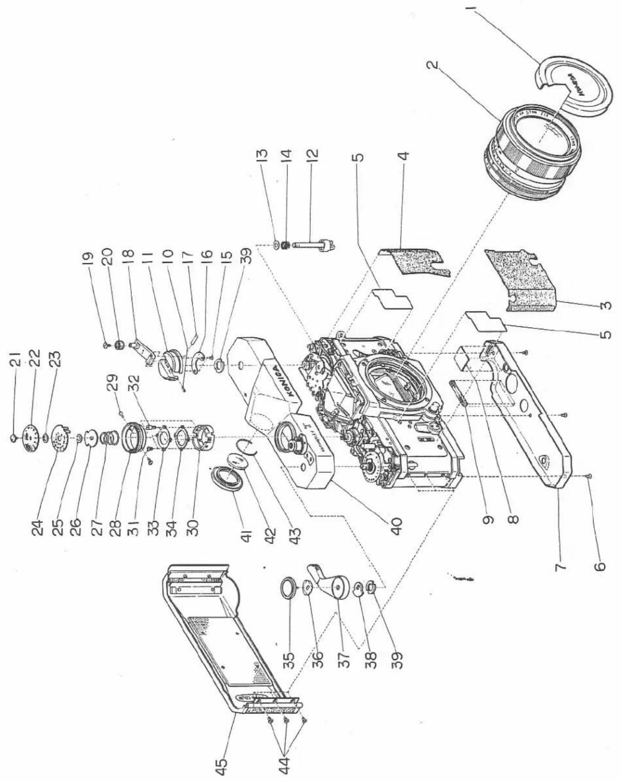
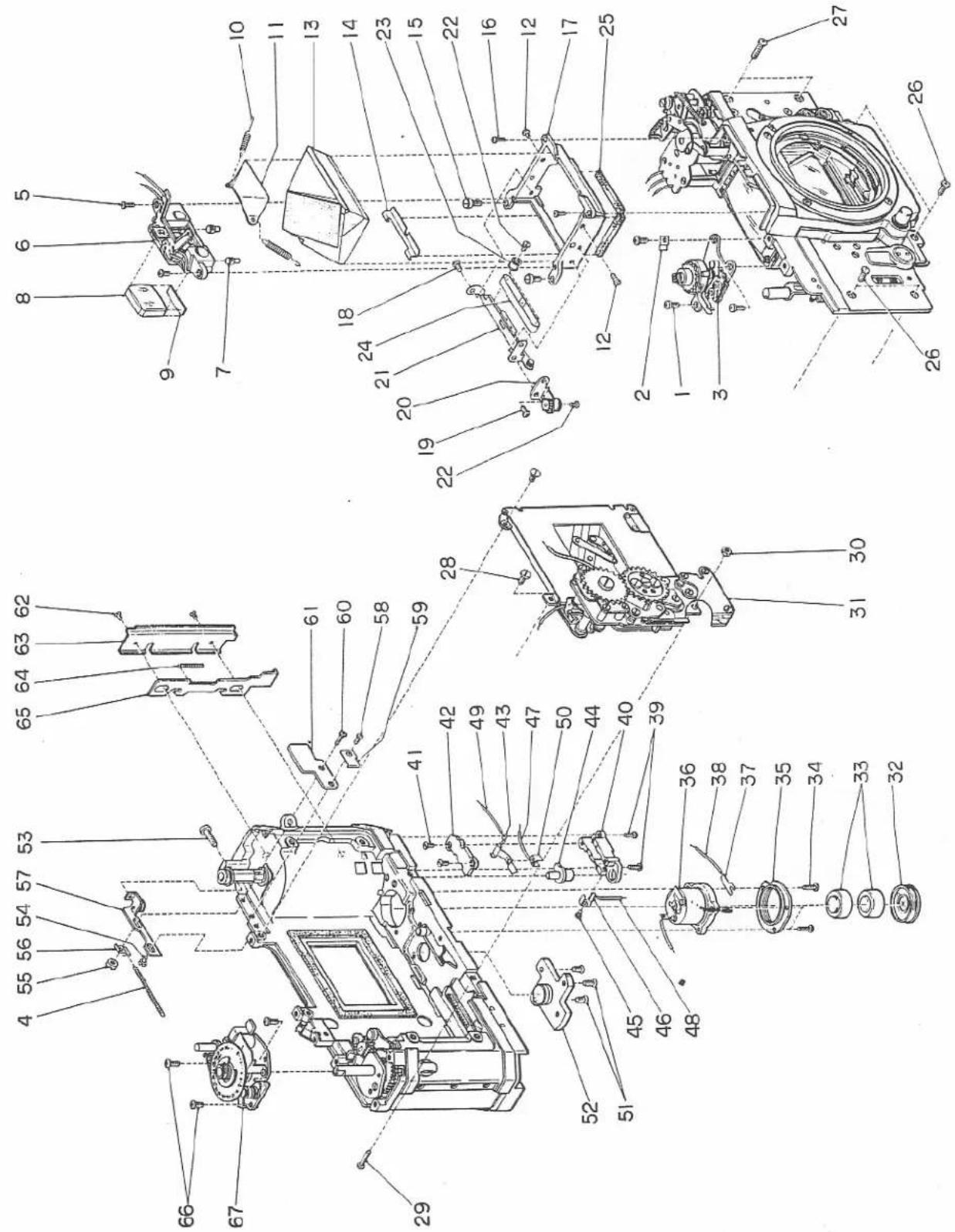
In case KONICA NEW AUTOREFLEX T is to be disassembled, the disassembling procedures should follow the order of Fig. No., and figure numbers of each drawing.
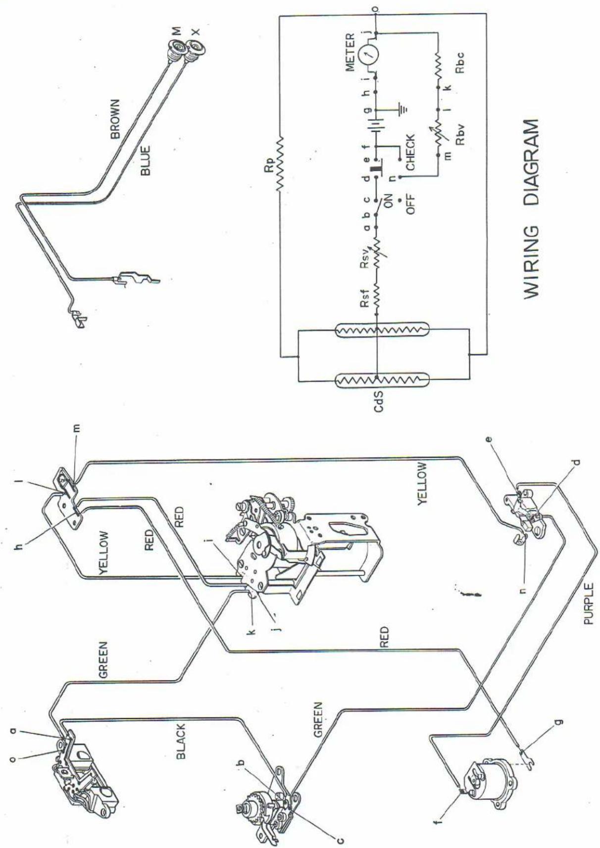
Fig. G shows wiring diagram of electronic circuit.
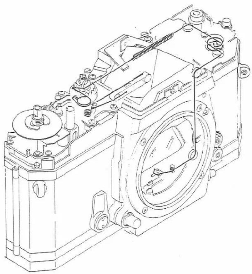
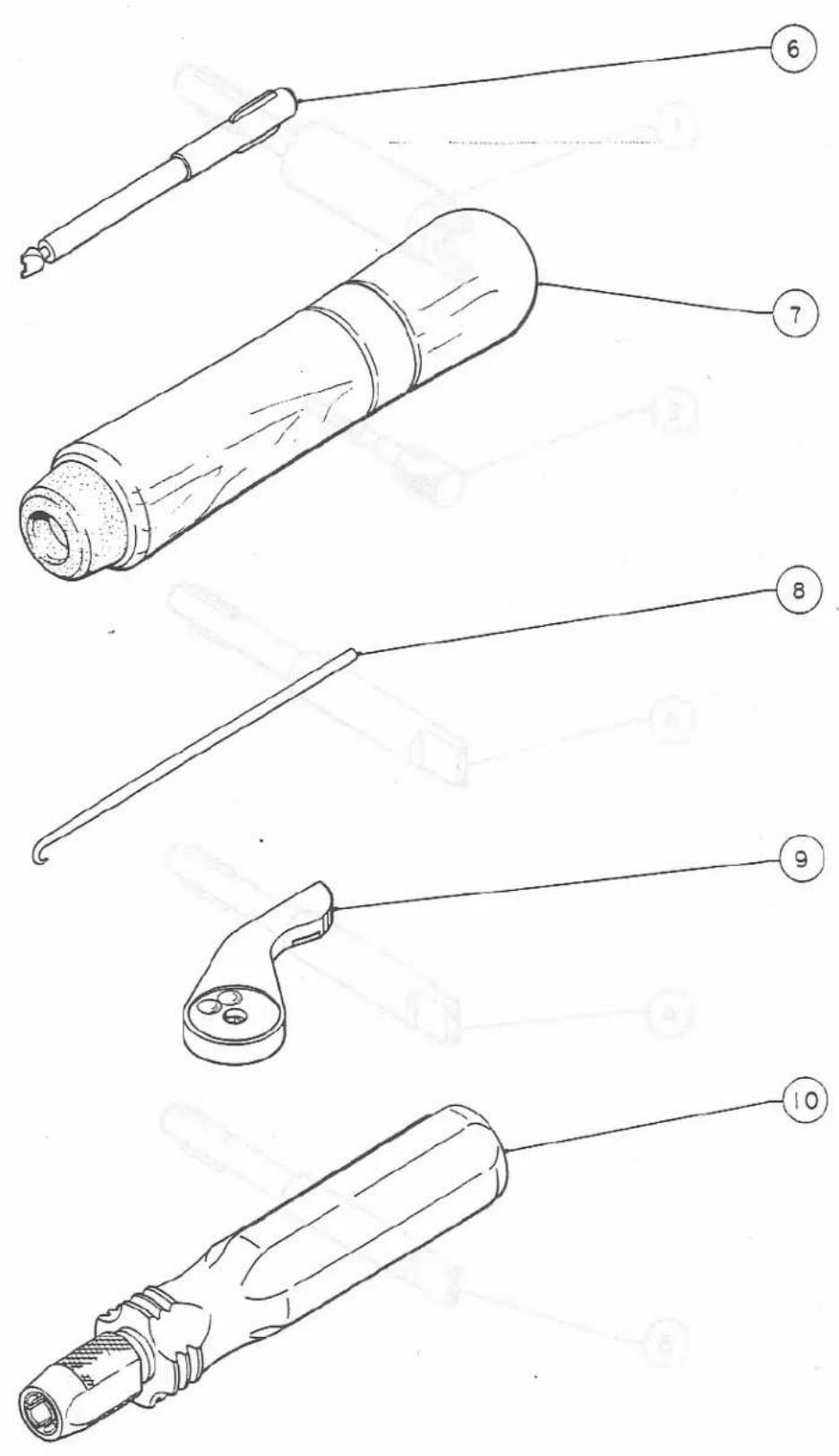
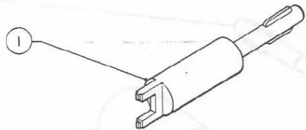
Fig. K shows how to set a yarn, and I shows special tools.
© To place an order for parts.
You are requested to indicate on your order sheet the model number, parts number (0××××) given in the second column, and parts name in the third or fourth column of the list so that the correct parts can be shipped to you.
No figure number is required.
To place an order for assembled parts.
You are requested to indicate on your order sheet the model number, the assembled parts number of three figures (×××) given in the second column, and parts name in the third or fourth column of the list so that the correct parts can be shipped to you.
No figure number is required.
© Note
This parts list includes the following three kinds of figures.
1) 0××××……Parts number
II) ×××××……Parts number of five figures
III) ×××……Assembled parts number of three figures
I) 0××××
Above group of series numbers are for the parts excluding the parts previously called common parts such as pins, tacks and screws, and this group of parts numbers are consolidated according to the parts of each mechanism, and as regards the parts body, covers, sprocket, etc., the parts numbers are also standardized (fixed).
For example, 05101 stands for the "Top cover" regardless of the model.
Therefore, it is impossible to ship the parts required if you place an order only with the parts number but without indicating the model number (model name).
II) ×××××
The parts such as pins, tacks and screws are called standard parts as they are standardized, and these parts correspond to the parts so far called common parts.
These parts are commonly used for all KONICA cameras regardless of model, that is to say, any of the parts indicated by numbers of five figures can be used with all KONICA models.
III) ×××
Assembled parts are indicated by a group of numbers of three figures.
Each one of three figures stands for:
-
- 3.
X X X
The first two figures (1.2) show the mechanism in which the parts is included.
For example,
10× Parts related to body mechanism
20× Parts related to winding mechanism
30× Parts related to shutter release mechanism.
IV) ★ Mark given to assembled parts indicates representing number of plural parts which are composed of inseparable parts.
You are requested to indicate on your order sheet the model number (camera name), parts number with ★ mark, and parts name so that the correct parts can be shipped to you.
© Column of note
The following four items referred to in the column of note.
-
Availability of special tools.
-
Attention required points when assembling or disassembling the cameras.
-
Availability of designated glue and lubricant.
As regards sections where adhesives/lubricant are to be used, refers to the column "Note" of each list.
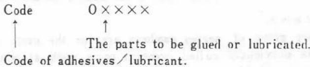
Code of adhesives/lubricant
Lubricant
E G - 4 ...... Ⓔ
Adhesives
Sundine 640 ……(S 640)
Aron alpha 201……(A201)
Black laquer……(B L)
- FTA shows that the parts or assembled parts are common to AUTOREFLEX T and NEW AUTOREFLEFLEX T.
Note: Some parts or assembled parts of AUTOREFLEX T and NEW AUTOREFLEX T have same numbers and are so slightly different from each other that they look quite the same. To prevent confusion in using them in repair work, indicate model number before parts or assembled parts number when request them.
Example : 2315-02001 ↑ Model number of AUTOREFLEX T 2355-02001 ↑ Model number of NEW AUTOREFLEX T
A 製番 2355
1 2 3 4 5 6
| Fig. NO. | Parts No. or Sub-assembly | 部品・部組名称 | Parts name or Sub-assembly name | Components | Note |
| A-1 | 501 | レンズキャップ | Lens cap | 07501, 07502 | FTA |
| A-2 | HEXANON F1.2 F1.4 F1.8 | レンズ | Lens | ||
| A-3 | 01003 | 左側光皮 | Leather (Left side) | (S640)-01001,05301,FTA | |
| A-4 | 01002 | 右側光皮 | Leather (Right side) | (S640)-01000,05301,FTA | |
| A-5 | 05389 | 穴フサギ板 | Plate for covering hole | (S640)-05301,FTA | |
| A-6 | 63429 | M1.7×2.5皿小ネジ | M1.7×2.5 Counter sunk screw | ||
| A-7 | 06201 | 底面カバー | Bottom cover | ||
| A-8 | 06203 | ショート防止黒紙 | Insulating black sheet | (S640)-01001,FTA | |
| A-9 | 06204 | 底面光線止め | Light tight (Bottom cover side) | (S640)-06201,FTA | |
| A-10 | 02410 | 巻戻しハンドル止めビス | Set screw for rewind knob | (S640)-02403,FTA | |
| A-11 | 02403 | 巻戻しハンドル | Rewind knob | FTA | |
| A-12 | 02401 | 巻戻し軸 | Rewind spindle | ◎-02402 | |
| A-13 | 02409 | 巻戻しフリクションバネ座金 | Friction spring washer | FTA | |
| A-14 | 02408 | 巻戻しフリクションバネ | Friction spring | FTA | |
| A-15 | 15259 | M1.4×1.4薄平小ネジ | M1.4×1.4 Thin flat screw | FTA | |
| A-16 | 02407 | レバー用バネ | Rewind spring | FTA | |
| A-17 | 02411 | 平行ピン | Straight pin | FTA | |
| A-18 | 02404 | 巻戻しレバー | Rewind crank | ◎-02405,FTA | |
| A-19 | 02412 | 巻戻しつまみ止めネジ | Set screw for rewind handle | FTA.left hand screw にねじ | |
| A-20 | 02405 | 巻戻しつまみ | Rewind handle | FTA | |
| A-21 | 04105 | シャッター数値板取付ネジ | Set screw for shutter speed plate | Special tool5,FTA | |
| A-22 | 04104 | シャッター数値板 | Shutter speed plate | ||
| A-23 | 04106 | ASA数値板座金 | ASA plate washer plate | FTA | |
| A-24 | 04107 | ASA数値板 | ASA plate |
A 製番 2355
1 2 3 4 5 6
| Fig. NO. | Parts No. or Sub-assembly | 部品・部組名称 | Parts name or Sub-assembly name | Components | Note |
| A-25 | 45289 | E型止め輪E-28 | E-ring E-28 | ||
| A-26 | 04108 | ASA板ストップ板 | ASA plate limiting stopper | FTA | |
| A-27 | 04109 | ASA切換用バネ | Spring for changing film sensibility | ||
| A-28 | 04101 | シャッタータイヤル | Shutter dial | ||
| A-29 | 04103 | シャッタータイヤル用ネジ | Screw for shutter dial | FTA | |
| A-30 | 04111 | ASA切換爪リング | Claw ring for changing ASA | ||
| A-31 | 04135 | ASAストップネジ | ASA stopper | ||
| A-32 | 61344 | M1.4×4.0平小ネジ | M1.4×4.0 Flat screw | ||
| A-33 | 04128 | シャッタータイヤル止めリング | Set ring for shutter dial | ||
| A-34 | 04134 | ASA切換爪リング | Claw for changing ASA | FTA | |
| A-35 | 02005 | 巻上げレバー止めネジ | Top screw for wind lever | Special tool 7, FTA | |
| A-36 | 02006 | 巻上げレバーフリクションバネ | Friction spring for wind lever | FTA | |
| A-37 | 02001 | 巻上げレバー | Wind lever | ||
| A-38 | 02007 | 巻上げ補強板 | Winding torque plate | FTA | |
| A-39 | 05111 | ファインダーカバーナット | Nut for setting top cover | Special tool 1, FTA | |
| A-40 | 511 a | ファインダーカバー | Top cover sub-assembly | 03001, 0300203004, 03012(03014),03013(03026(2)),03015 | For Autoreflex-T(Export model)(輸出向) |
| A-40 | 511 b | ファインダーカバー | Top cover sub-assembly | 03028, 0411204119, 0510105102, 0510305104, 0521716304(3).51169 | For FTA(Domestic model)(国内向) |
| A-41 | 05216 | 接眼枠 | Eyepiece frame | ||
| A-42 | 05226 | アイピースガラス | Eyepiece glass | ||
| A-43 | 05229 | アイピースガラス止めバネ | Set spring for eyepiece glass | ||
| A-44 | 06015 | 蝶番止めネジ | Hinge set screw | FTA |
A 製番 2355
1 2 3 4 5 6
| Fig. NO. | Parts No. or Sub-assembly | 部品·部組名称 | Parts name or Sub-assembly name | Components | Note |
| A-45 | 601 | 裏蓋 | Backlid sub-assembly | 06001, 0600206003, 06004(4), 06005(4),06010(2),06011, 0601306014, 0601606017, 91118 |
A
B 製番 2355
| Fig. NO. | Parts No. or Sub-assembly | 部品・部組名称 | Parts name or Sub-assembly name | Components | Note |
| B-1 | 61444 | M1.7×3.0平小ネジ | M1.7×3.0 Flat screw | ||
| B-2 | 08234 | リード線押え | Lead wire holder | ||
| B-3 | 411 | シャッターダイヤル軸 | Shutter dial shaft sub-assembly | 04110, 0411304114, 0412204123, 0412404125, 0412704133, 0413604137, 0822808229, 08230(2), 08231(2),51209, 61344(2), 63315(2) | 04114と04137は調整用座金で, 負数は不定です。04114 and 04137 are adjusting washers.Quantities are not certain. |
| B-4 | 08054 | Tプーリー補助バネ | Complementary spring | FTA | |
| B-5 | 61344 | M1.4×4.0平小ネジ | M1.4×4.0 Flat screw | ||
| B-6 | 821 | 露出計(受光部) | Exposure meter (CdS sub-assembly) | ||
| B-7 | 05224 | アイピース止めネジ | Set screw for eyepiece | FTA | |
| B-8 | *05214 | アイピース | Eyepiece | 05214, 05215 | FTA |
| B-9 | 05223 | アイピースワッシャー | Eyepiece washer | FTA | |
| B-10 | 05218 | ペンタ押えバネ | Spring for holdingpenta-prism | FTA | |
| B-11 | 05206 | ペンタ押え | Penta-prism holder | FTA | |
| B-12 | 61424 | M1.7×2.5平小ネジ | M1.7×2.5 Flat screw | ||
| B-13 | *05203 | ペンタブリズム | Penta-prism | 05202, 0520305204, 0520505220 | |
| B-14 | 08088 | T目盛枠 | Shutter speed frame | ||
| B-15 | 05219 | ペンタ枠止めネジ | Set screw for penta-prismframe | ||
| B-16 | 61344 | M1.4×4.0平小ネジ | M1.4×4.0 Flat screw | ||
| B-17 | 05201 | ペンタ枠 | Penta-prism frame | ||
| B-18 | 65395 | M1.7×1.8薄平小ネジ | M1.7×1.8 Thin flat screw | ||
| B-19 | 61444 | M1.7×3.0平小ネジ | M1.7×3.0 Flat screw | ||
| B-20 | 812 | 連動保持板 | Support plate for pursuedgear sub-assembly | 08069, 0807208073, 0807508086 |
B 製番 2355
1 2 3 4 5 6
| Fig. NO. | Parts No. or Sub-assembly | 部品・部組名称 | Parts name or Sub-assembly name | Components | Note |
| B-21 | 813 | 速度表示板 | Plate for indicating shutter speed sub-assembly | 08067, 0807408078(2),08089 | |
| B-22 | 08073 | ブーリー止めネジ | Set screw for pulley | ||
| B-23 | 08077 | ブーリーA | Pulley A | ||
| B-24 | 814 | 速度目盛板 | Belt for indicating shutter speed sub-assembly | 08083,08084 | |
| B-25 | 05232 | 防塵パッキン | Dust proof packing | (S640)-05201 | |
| B-26 | 65575 | M2×30薄平小ネジ | M2×3.0 Thin flat screw | ||
| B-27 | 65605 | M2×4.5 薄平小ネジ | M2×4.5 Thin flat screw | ||
| B-28 | 61584 | M2×3.5 平小ネジ | M2×3.5 Flat screw | ||
| B-29 | 04002 | シャッター取付ネジB | Set screw B for shutter | ||
| B-30 | 04003 | 六角ナット | Nut | FTA | |
| B-31 | 402 | シャッター | Shutter sub-assembly | 401, 04004(2) | |
| B-32 | 08301 | 電池蓋 | Battery cap | FTA | |
| B-33 | 08351 | 水銀電池 | Mercury battery | FTA | |
| B-34 | 65484 | M1.7×5.0薄平小ネジ | M1.7×5.0 Thin flat screw | ||
| B-35 | 08308 | 電池ケースネジ | Battery case screw | FTA | |
| B-36 | 831 | バッテリーケース | Battery case sub-assembly | 08302, 0830408305, 08305 | |
| B-37 | 08310 | プラス接片 | Plas rog plate | FTA | |
| B-38 | 08311 | プラスリード線 | Plus lead wire | ||
| B-39 | 65465 | M1.7×4.0薄平小ネジ | M1.7×4.0 Thin flat screw | ||
| B-40 | 08401 | チェックスイッチ | Battery check switch | FTA | |
| B-41 | 23390 | 特M1.4×2.8皿小ネジ | M1.4×2.8 Special counter sunk screw | ||
| B-42 | 08402 | チェックスイッチ基板 | Base plate for check switch | FTA | |
| B-43 | 08403 | チェック接片 | Battery check contact plate | FTA | |
| B-44 | 08406 | チェック釦 | Battery check button | FTA |
B 製番 2355
1 2 3 4 5 6
| Fig. NO. | Parts No. or Sub-assembly | 部品・部組名称 | Parts name or Sub-assembly name | Components | Note |
| B-45 | 25290 | 特M1.4×2.2薄平小ネジ | M1.4×2.2 Special thin flat screw | ||
| B-46 | 08405 | 固定接片 | Fix contact plate | FTA | |
| B-47 | 08312 | マイナスリード線A | Minus-lead wire A | ||
| B-48 | 08313 | チェックリード線 | Battery check lead wire | ||
| B-49 | 08314 | マイナスリード線B | Minus-lead wire B | ||
| B-50 | 08404 | マイナス接点 | Minus-contact point | FTA | |
| B-51 | 63474 | M1.7×4.5皿小ネジ | M1.7×4.5 Counter sunk screw | ||
| B-52 | 06202 | 三脚ネジ | Tripod socket | FTA | |
| B-53 | 08066 | 長平小ネジ | Long flat screw | ||
| B-54 | 61424 | M1.7×2.5平小ネジ | M1.7×2.5 Flat screw | ||
| B-55 | 08057 | 調整板止めナット | Nut for setting regulating plate | Special tool 6, FTA | |
| B-56 | 08034 | 補助バネ掛け | Complementary spring stud | FTA | |
| B-57 | 804 | 調整板 | Regulating plate | 08032, 0803308051, 08053 | |
| B-58 | 61424 | M1.7×2.5平小ネジ | M1.7×2.5 Flat screw | ||
| B-59 | 08315 | リード線押え | Lead wire holder | ||
| B-60 | 65484 | M1.7×5.0薄平小ネジ | M1.7×5.0 Thin flat screw | ||
| B-61 | 08407 | チェック抵抗板 | Check resistor plate | ||
| B-62 | 63315 | M1.4×2.8皿小ネジ | M1.4×2.8 Counter sunk screw | ||
| B-63 | 06102 | 締り爪覆り板 | Lock claw cover | FTA | |
| B-64 | 06104 | 締り爪ベネ | Lock claw spring | FTA | |
| B-65 | 06101 | 締り爪 | Lock claw (Body side) | E-06102, 01001, FTA | |
| B-66 | 61444 | M1.7×3.0平小ネジ | M1.7×3.0 Flat screw | ||
| B-67 | 231 | 指数器 | Film counter sub-assembly | 02301~0231803022, 0302303024, 0302508227, 4558961424 |
[NO TEXT]
C 製番 2355
1 2 3 4 5 6
| Fig. NO. | Parts No. or Sub-assembly | 部品・部組名称 | Parts name or Sub-assembly name | Components | Note |
| C-1 | 45209 | E型止メ輪E-20 | E ring E-20 | ||
| C-2 | 02032 | 巻上げリンク | Connector for shutter set ing | ◎-02033, 209 | |
| C-3 | 02012 | 巻上げ規制板止めネジ | Set screw for winding regulating ratchet | (S640)-02058, FTA | |
| C-4 | 207 | 二重巻上げストップ板 | Plate stopping double wind sub-assembly | 02033, 02058 | |
| C-5 | 02034 | 規制板座金 | Washer for regulating ratchet | FTA | |
| C-6 | 02011 | 巻上げ規制板 | Winding regulated ratchet | ||
| C-7 | 02021 | 巻上げ軸ガタ取り座金 | Washer | 02021 (t=0.1)02030 (t=0.2) | |
| C-8 | 02018 | 巻上げ軸復元バネ掛けA | Spring stud A | FTA | |
| C-9 | 02017 | 巻上げ軸復元バネ | Recoiling spring for winding | Special tool 8, FTA | |
| C-10 | 63425 | M1.7×2.5皿小ネジ | M1.7×2.5 Counter sunk screw | ||
| C-11 | 02004 | 巻上げ下部軸受 | Lower metal for wind shaft | FTA | |
| C-12 | 201 | 巻上げ軸 | Wind shaft sub-assembly | 02002, 0201602022(02076)02023, 0202402026, 02077 | ◎-02004, 231 |
| C-13 | 02020 | 巻上げカム | Wind cam | ◎-206, FTA | |
| C-14 | 61444 | M1.7×3.0平小ネジ | M1.7×3.0 Flat screw | ||
| C-15 | 206 | 巻上げ歯車地板 | Base plate for wind gear sub-assembly | 02003, 0203602037, 0203802039, 0204102042, 0204302044, 0204502046(2),02047(2),02075, 0232203029 | |
| C-16 | 02031 | リール歯車 | Spool gear | ◎-02028, 206, FTA | |
| C-17 | 02028 | リール歯車座金 | Spool gear washer | FTA | |
| C-18 | 02069 | リール座金 | Spool washer | FTA | |
| C-19 | 02067 | リール内筒 | Inner spool | FTA |
C 製番 2355
1 2 3 4 5 6
| Fig. NO. | Parts No. or Sub-assembly | 部品・部組名称 | Parts name or Sub-assembly name | Components | Note |
| C-20 | 02027 | リール外筒 | Outer spool | FTA | |
| C-21 | 02068 | リールバネ | Spool spring | ||
| C-22 | 02029 | リールフリクション バネ | Friction plate | ◎-02067 | |
| C-23 | 02207 | スプロケット軸止め レバー軸 | Stop lever center for sprocket shaft | ||
| C-24 | 02208 | スプロケット軸止め レバーバネ | Stop lever spring for sprocket shaft | ||
| C-25 | 02206 | スプロケット軸止め レバー | Stop lever for sprocket shaft | ◎-02207,FTA | |
| C-26 | 45249 | E型止メ輪E-24 | E ring E-24 | ||
| C-27 | 02209 | スプロケット座金 | Sprocket washer | FTA | |
| C-28 | 02205 | スプロケットバネ | Sprocket coil spring | FTA | |
| C-29 | 02204 | スプロケットネジ | Sprocket screw | FTA | |
| C-30 | 221 | スプロケット軸 | Sprocket shaft sub-assembly | 02202, 02210 | ◎-01001, 02203 |
| C-31 | 02203 | スプロケット歯車 | Sprocket gear | ◎-206 | |
| C-32 | 02201 | スプロケット | Sprocket | FTA | |
| C-33 | 02053 | 巻上げラックガイド 軸 | Guid pin for wind rack | FTA | |
| C-34 | 61584 | M2×3.5 平小ネジ | M2×3.5 Flat screw | ||
| C-35 | 02052 | 巻上げラック押え板 | Guide plate for wind rack | ||
| C-36 | 209 | 巻上げラック | Wind rack sub-assembly | 02050(02051)02057, 02060 | ◎-01001, 02052, 02053 |
| C-37 | 45179 | E型止メ輪E-17 | E ring E-17 | ||
| C-38 | 02055 | 二重巻上げストッパ ー外しレバー | Release lever for double wind prevention stopper | ◎-101 | |
| C-39 | 02056 | 二重巻上げストッパ ーバネ | Spring for double wind prevention stopper | ||
| C-40 | 02064 | 外しレバーバネ | Spring for release lever | FTA | |
| C-41 | 02015 | 二重巻上げストッパ ー軸 | Center for double wind prevention stopper | ||
| C-42 | 208 | 二重巻上げストッパ ー | Double wind prevention stopper sub-assembly | 02035, 02054 | ◎-02015 |
| C-43 | 03008 | レリーズ安全レバー 軸 | Center for lever regulating release | FTA |
C 製番 2355
| Fig. NO. | Parts No. or Sub-assembly | 部品・部組名称 | Parts name or Sub-assembly name | Components | Note |
| C-44 | 03009 | レリーズ安全レバーパネ | Spring for lever regulating release | FTA | |
| C-45 | 03007 | レリーズ安全レバー | Lever regulating release | E-03008, FTA | |
| C-46 | 02019 | 規制爪取付ネジ | Set screw for wind regulation claw | FTA | |
| C-47 | 02013 | 規制爪軸 | Screw for wind regulation claw | FTA | |
| C-48 | 02014 | 規制爪 | Wind regulation claw | E-02013 | |
| C-49 | 02070 | 規制爪バネ | Spring for windregulation claw | FTA | |
| C-50 | 02065 | 規制爪バネ掛け | Spring stud for wind regulation claw | FTA | |
| C-51 | 02025 | 戻しバネ掛け | Returing spring stud | FTA | |
| C-52 | 01013 | 吊環金具止めネジ(a) | Set screw (a) for strap eyelet | (S640)-01001, 01004, FTA | |
| C-53 | 01015 | 吊環金具止めネジ(b) | Set screw (b) for strap eyelet | (S640)-01001, 01004, FTA | |
| C-54 | 01004 | 吊環金具 | Strap eyelet | (BL)-01001, FTA | |
| C-55 | 63444 | M1.7×3.0皿小ネジ | M1.7×3.0 Counter sunk screw | ||
| C-56 | 805 | T連動ブーリー | T pulley sub-assembly | 08030, 0803708048, 08049 | |
| C-57 | 08036 | Tブーリー軸 | T pulley center | FTA | |
| C-58 | 08048 | T連動Aブーリー | T pulley | E-08036, FTA | |
| C-59 | 01006 | 蝶番側光線止め | Light tight (Hinge side) | [S640]-01001, FTA | |
| C-60 | 01008 | 本体溝光線止め | Light tight (Body groove) | [S640]-01001, FTA | |
| C-61 | 06103 | 締り爪案内ネジ | Lack claw guide | FTA | |
| C-62 | 01016 | シャッター裏側光線止め | Light tight (Back side of shutter) | (S640)-01001, FTA | |
| C-63 | 101 | 本体 | Body sub-assembly | 01001, 02062(2), 02402 |
C
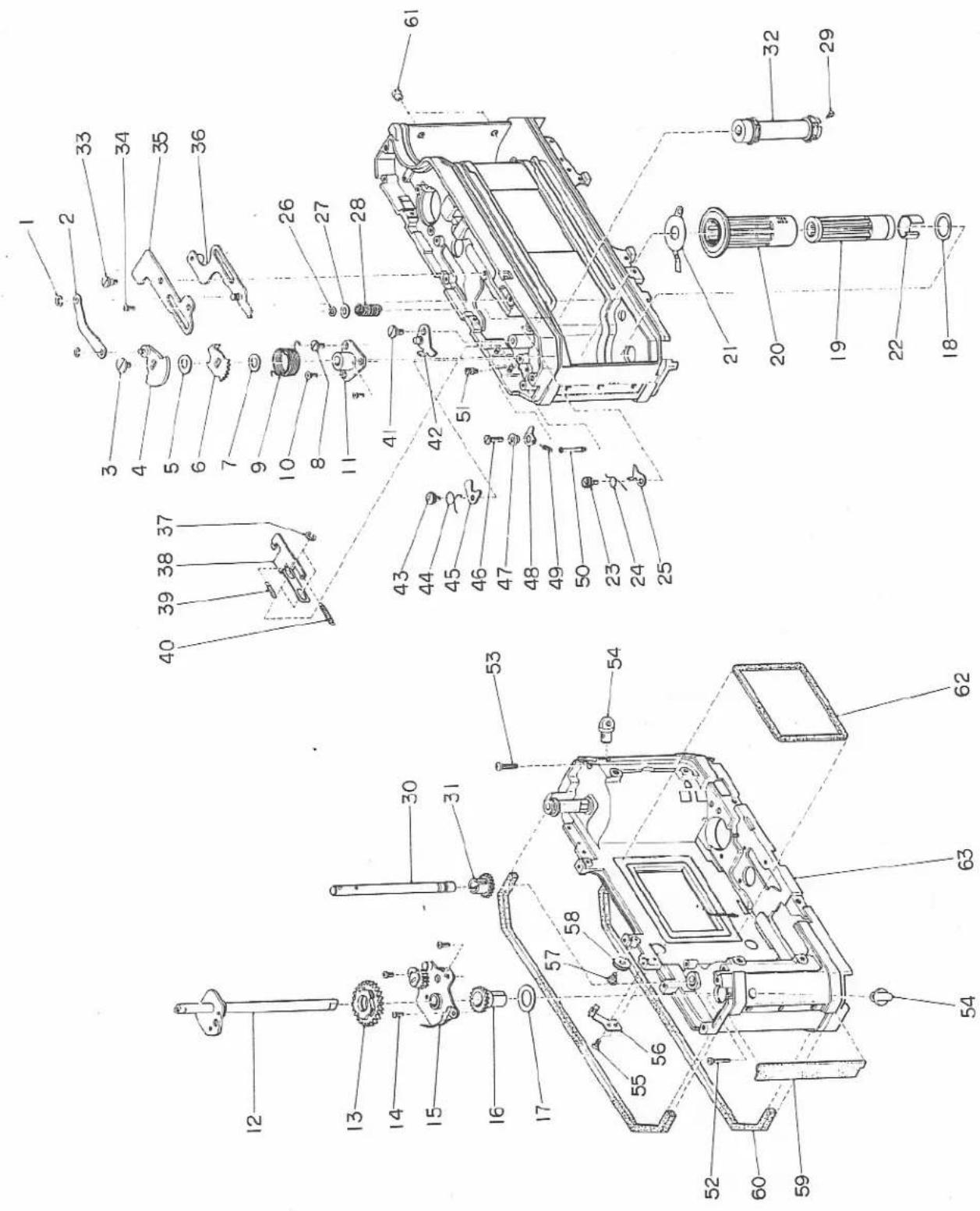
D 製番 2355
| Fig. NO. | Parts No. or Sub-assembly | 部品・部組名称 | Parts name or Sub-assembly name | Components | Note |
| D-1 | 63444 | M1.7×3.皿小ネジ | M1.7×3.0 Counter sunk screw | ||
| D-2 | 821 | 露出計(メーター部) | Exposure meter (Meter sub-assembly) | ||
| D-3 | 11470 | M1.7×4.5平小ネジ | M1.7×4.5 Flat screw | ||
| D-4 | 05231 | フレネル枠取付ネジ | Set screw for fresnel frame | FTA | |
| D-5 | 05207 | フレネル枠 | Fresnel frame | ||
| D-6 | 11400 | M1.7×2.0平小ネジ | M1.7×2.0 Flat screw | ||
| D-7 | 05213 | コンデンサー押えB | Condenser holder B | ||
| D-8 | 05221 | フレネル支持板 | Fresnel holder | ||
| D-9 | 05211 | ビント調整ネジA | Focus adjust screw | FTA | |
| D-10 | 05222 | コンデンサー押え止めネジ | Set screw for condenser holder | FTA | |
| D-11 | 05212 | コンデンサー押えA | Condenser holder A | ||
| D-12 | 05209 | コンデンサー | Condenser lens | ||
| D-13 | 05210 | 中間座金 | Mid washer | ||
| D-14 | 05208 | フレネルレンズ | Fresnel lens | ||
| D-15 | 05227 | 防塵テープ | Tape for dust proof | FTA | |
| D-16 | 05401 | マウント座 | Lens mount | ||
| D-17 | 65619 | M2×5.0 薄平小ネジ | M2×5.0 Thin Flat screw | ||
| D-18 | 61309 | M1.4×2.5平小ネジ | M1.4×2.5 Flat screw | ||
| D-19 | 05402 | マウントパネ | Mount spring | FTA | |
| D-20 | 05417 | マウント音止め | Neopuren stopping sound | (S640)-05401 | |
| D-21 | 05409 | フランジバック調整座金 | Regulating washer for frange back | FTA, 05410~05416 are are available. | |
| D-22 | 65395 | M1.7×1.8皿小ネジ | M1.7×1.8 Counter sunk screw | ||
| D-23 | 61309 | M1.4×2.5平小ネジ | M1.4×2.5 Flat screw | ||
| D-24 | 538 | 前面カバー | Front cover sub-assembly | 05386, 05387 08019 | |
| D-25 | 08020 | 絞リリング受け止めネジ | Set screw Aperture ring cover | FTA | |
| D-26 | 08008 | 絞リリング受け | Aperture ring cover |
D 製番 2355
1 2 3 4 5 6
| Fig. NO. | Parts No. or Sub-assembly | 部品・部組名称 | Parts name or Sab-assembly name | Camponents | Note |
| D-27 | *08006 | 絞りリング | Aperture ring | 08006, 0800708019 | FTA |
| D-28 | 08041 | バネ掛けA | Spring stud A | FTA | |
| D-29 | 08011 | 爪取付けネジ | Claw set screw | ||
| D-30 | 08012 | 絞りリング爪スプリング | Spring for aperture ring claw | ||
| D-31 | 811 | 絞りリング爪 | Aperture ring claw | 08009, 08081 | |
| D-32 | 05385 | セルフレバー止めネジ | Set screw for self-timer lever | FTA(S640)-598 Special tool 4 | |
| D-33 | 05380 | セルフレバー | Self-timer lever | FTA | |
| D-34 | 598 | セルフ軸 | Self-timer shaft sub-assembly | 05383, 05384 | |
| D-35 | 111 | シンクロソケット | Synchro socket sub-assembly | 01102(2),01103(2),01104(2),01105(2) | Special driver 3,FTA |
| D-36 | 08017 | オートマニアル切替止めネジ | Set screw for auto-manual change | FTA | |
| D-37 | 801 | オートマニアル切替ピン | Auto-manual change pin sub-assembly | 08013, 0801408016, 08038 | Instead of 08014, 08060is also available.◎-45301 |
| D-38 | 08025 | オートマニアル切替ピン調整座金 | Regulation washer for auto-manual change | 08070 (t=0.05) is also available. | |
| D-39 | *08015 | オートマニアル切替軸 | Shaft changing auto-manual | 08015, 08018 | FTA |
| D-40 | 08024 | 地板止めネジ | Set screw for base plate | FTA | |
| D-41 | 08023 | オートマニアル切替表示板 | Expression plate of auto-manual change | ◎-08024 | |
| D-42 | 08021 | 切替表示パネ | Spring for expression plate | ||
| D-43 | 63294 | M1.4×2.2皿小ネジ | M1.4×2.2 Counter sunk screw | ||
| D-44 | 05345 | フレネル枠台B | Support B for fresnel frame | ||
| D-45 | 05230 | ピント調整ネジ | Focus adjust screw | FTA | |
| D-46 | 08063 | F値調整地板止めネジ | Set screw for plate regulating F-value | FTA |
D 製番 2355
| Fig. NO. | Parts No. or Sub-assembly | 部品·部組名称 | Parts name or Sub-assembly name | Components | Note |
| D-47 | 08064 | F值調整地板止のネジB | Set screw B for plate regulating F-value | FTA | |
| D-48 | 807 | F值調整地板 | Plate regulating F-value | 08035, 08062 08065, 08090 | FTA |

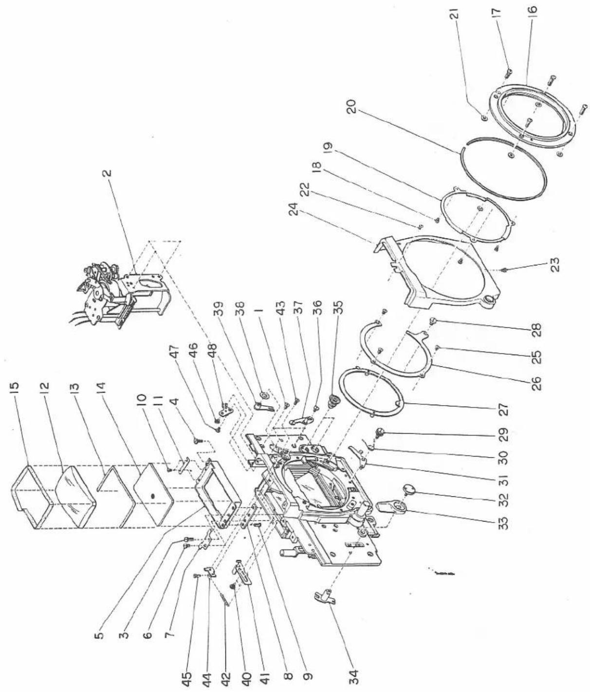
E 製番 2355
| Fig. NO. | Parts No. or Sub-assembly | 部品・部組名称 | Parts name or Sub-assembly name | Components | Note |
| E-1 | 03011 | レリーズバネ | Release spring | ||
| E-2 | 08003 | 作動レバーAバネ | Working lever A spring | FTA | |
| E-3 | 03027 | レリーズレバー軸 | Release lever center | FTA | |
| E-4 | 301 | レリーズレバー | Release lever sub-assembly | 03003, 0300503006, 0301808005 | Instead of 03018,03019and 03020 are available.◎-03027 |
| E-5 | 05396 | ミラー復座レバー軸 | Shaft for mirrer restoring | ||
| E-6 | 05362 | ミラー復座レバーバネ | Spring for mirror restor-ing lever | ||
| E-7 | 535 | ミラー復座レバー | Mirror restoring lever sub-assembly | 05361, 05364(2) | ◎-05396 |
| E-8 | 05306 | ミラー作動レバーAバネ | Spring for mirror working lever A | ||
| E-9 | 05317 | ミラー作動レバーA止めネジ | Set screw for mirror working lever A | ||
| E-10 | 593 | ミラー作動レバーA | Mirror working lever A sub-assembly | 05314, 0532205368 | ◎-05317 |
| E-11 | 05335 | 座金 | Washer | FTA | |
| E-12 | 05505 | タンブラーバネ | Tumbler spring | ◎-534 | |
| E-13 | 05506 | タンブラー板止めネジ | Set screw for tumbler plate | ||
| E-14 | 551 | タンブラー | Tumbler sub-assembly | 05503, 05504 | ◎-05506, 531 |
| E-15 | 45179 | E型止メ輪E-17 | E ring E-17 | ||
| E-16 | 05330 | 自動絞りワッシャー | Washer for automatic aperture control | 05369 (t=0.2) is also available. | |
| E-17 | 534 | チャージアーム | Charge arm sub-assembly | 05304(2),0532705349,0535005352, 0535605357, 05501 | ◎-531 |
| E-18 | 533 | 自動絞り | Automatic aperture control sub-assembly | 05325, 0533605337, 0534105342, 0534305344, 0534605348, 05358 | ◎-531 |
| E-19 | 05319 | ミラー作動レバーB止めネジ | Set screw for mirror working lever B | ||
| E-20 | 05347 | ロック爪外しレバー | Lever for removing claw | ◎-05319 | |
| E-21 | 05388 | 手動絞りレバーA軸 | Shaft for manual aperture lever A | FTA |
E 製番 2355
1 2 3 4 5 6
| Fig. NO. | Parts No. or Sub-assembly | 部品・部組名称 | Parts name or Sub-assembly name | Components | Note |
| E-22 | 05372 | 手動絞りバネ | Manual aperture spring | FTA | |
| E-23 | 05367 | 手動絞りレバーA | Manual aperture lever A | ◎-05388, FTA | |
| E-24 | 03027 | レリーズレバー軸 | Release lever center | FTA | |
| E-25 | 595 | 手動絞り | Manual aperture sub-assembly | 05381, 05394 | ◎-03027, FTA |
| E-26 | 05365 | 手動絞り座金 | Manual aperture washer | FTA | |
| E-27 | 05379 | レリーズレバーC バネ | Spring for release lever C | ||
| E-28 | 05397 | レリーズレバーB 軸 | Shaft for release lever B | ||
| E-29 | 05359 | レリーズレバーC | Release lever C | ◎-05397 | |
| E-30 | 05395 | レリーズレバーB | Release lever B | ◎-05397 | |
| E-31 | 05399* | レリーズレバーA 軸 | Shaft for release lever A | ||
| E-32 | 532 | レリーズレバーA | Release lever A sub-assembly | 05391, 05393 | ◎-05399 |
| E-33 | 05371 | 巻上げ解除レバー軸 | Shaft for wind release lever | FTA | |
| E-34 | 05370 | 巻上げ解除レバー | Wind release lever | ◎-05371, 535, FTA | |
| E-35 | 65414 | M1.7×2.2薄平小ネジ | M1.7×2.2 Thin flat screw | ||
| E-36 | 596 | 連動レバーA | Pursued lever A sub-assembly | 05373, 05374 05375, 05377 | |
| E-37 | 05366 | 手動絞り釦 | Manual aperture control button | ◎-531, FTA | |
| E-38 | 08002 | レバー軸 | Lever shaft | FTA | |
| E-39 | 809 | 紋りリング作動レバー | Aperture ring working lever sub-assembly | 08001, 08004 | ◎-08002 |
| E-40 | 61424 | M1.7×2.5平小ネジ | M1.7×2.5 Flat screw | ||
| E-41 | 591 | 連動レバーB | Pursued lever B sub-assembly | 05376, 05378 05392 | |
| E-42 | 05321 | シャッターレリーズレバー軸 | Shaft for shutter release lever | ||
| E-43 | 05323 | シャッターレリーズレバー | Shutter release lever | ◎-05321 | |
| E-44 | 05319 | ミラー作動レバーB止めネジ | Set screw for mirror working lever B | ||
| E-45 | 592 | ミラー作動レバーB | Mirror working lever B | 65315, 05322 | ◎-05391 |
E 製番 2355
| 1 | 2 | 3 | 4 | 5 | 6 |
| Fig. NO. | Parts No. or Sub-assembly | 部品・部組名称 | Parts name or Sub-assembly name | Components | Note |
| E-46 | 05335 | 座金 | Washer | FTA | |
| E-47 | 05318 | ミラー作動レバーバネ掛け | Spring stud for mirror working lever | ||
| E-48 | 05398 | レリーズレバーBバネ | Release lever B spring | ||
| E-49 | 61424 | M1.7×2.5平小ネジ | M1.7×2.5 Flat screw | ||
| E-50 | 05312 | ゴム押え板 | Supporting plate for damper | ||
| E-51 | 05360 | ストッパーヴム | Damper | ||
| E-52 | 61424 | M1.7×2.5平小ネジ | M1.7×2.5 Flat screw | ||
| E-53 | 08052 | F値プーリー地板用座金 | Washer for F-value pulley plate | ||
| E-54 | 08055 | F値プーリー地板 | F-value pulley plate | ||
| E-55 | 61444 | M1.7×3.0平小ネジ | M1.7×3.0 Flat screw | ||
| E-56 | 08031 | F値プーリー軸A | Shaft for F-value pulley A | ||
| E-57 | 08035 | F値連動Aプーリー | F-value pulley A | FTA | |
| E-58 | 08056 | 紐外れ防止板C | Protecter C of string | ||
| E-59 | 05408 | レンズ止め金具軸 | Shaft for lens set metal | ||
| E-60 | 05407 | レンズ止め金具バネ | Spring for lens set metal | ||
| E-61 | 05405 | レンズ止め金具 | Lens set metal | ◎-05408 | |
| E-62 | 05406 | レンズ止め金具バネ掛け | Spring stud for lens set metal | ||
| E-63 | 05404 | レンズ着脱知 | Button for lens change | ◎-531 | |
| E-64 | 08045 | 連結レバー軸 | Shaft for Connecting lever | ||
| E-65 | 806 | 連結レバー | Connection lever sub-assembly | 08043, 0804408045, 0804708058, 08059 | ◎-08045 |
| E-66 | 08028 | F値レバー止めネジ | Set screw for F-value lever | FTA | |
| E-67 | 802 | F値レバー | F-value lever sub-assembly | 08026, 0802708050, 65414 | ◎-08028, FTA |
| E-68 | 02025 | 戻しバネ掛け | Returing spring stud | FTA | |
| E-69 | 05318 | ミラー作動レバーバネ掛け | Spring stud for mirror working lever |
E 製番 2355
1 2 3 4 5 6
| Fig. NO. | Parts No. or Sub-assembly | 部品·部組名称 | Parts name or Sub-assembly name | Components | Note |
| E-70 | 45179 | E型止め輪E-17 | E ring E-17 | ||
| E-71 | 05414 | フランジバッグ調整座金 | Regulating washer for frange back | FTA 05409~05416 (t=0.03~0.4) | |
| E-72 | 05338 | ミラー保持バネ | Spring supporting mirror | ||
| E-73 | 05324 | ミラー保持バネ掛け | Stud for spring supporting mirror | ||
| E-74 | 45135 | E型止め輪E-13 | E ring E-13 | ||
| E-75 | 537 | ミラー | Mirror sub-assembly | 05303, 0530505307(05309(4), 05326,05328), 05310(2), 05313,05333 | |
| E-76 | 45105 | E型止め輪E-10 | E ring E-10 | ||
| E-77 | 539 | ミラー枠さささ板 | Supporting plate for mirror frame sub-assembly | 05316(05320)05329 | E-531 |
| E-78 | 65395 | M1.7×1.8薄平小ネジ | M1.7×1.8 Thin flat screw | ||
| E-79 | 05363 | 進光枠 | Light shield frame | ||
| E-80 | 531 | ミラーボックス | Mirror box sub-assembly | 03010, 0530105302, 05308(2), 05311,05331, 0533205339, 0534005354, 0550206205 |
W
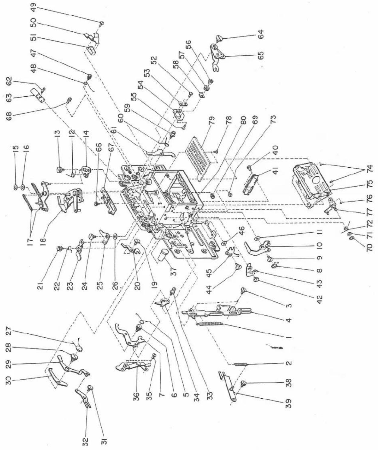
F 製番 2355
1 2 3 4 5 6
| Fig. NO. | Parts No. or Sub-assembly | 部品・部組名称 | Parts name or Sub-assembly name | Components | Note |
| 206 | |||||
| F-1 | 02075 | 画面重な防止ガイド板 | Overlapping preventive Guide | (S640)-02026 | |
| F-2 | 02043 | 中間歯車C軸押えネジ | Cap for idle gear C | FTA | |
| F-3 | 02041 | 中間歯車C | Idle gear C | E-02042,FTA | |
| F-4 | *04133 | 巻上げ歯車地板 | Base plate for wind gear | 02003, 0203602037, 0203802039, 0204202044, 0204502046(2),02047(2),02322, 03029 | |
| 411 | |||||
| F-5 | 63315 | M1.4×2.8皿小ネジ | M1.4×2.8 Counter sunk screw | ||
| F-6 | 04110 | ASA切換ギヤー | Gear for changing ASA | ||
| F-7 | *04133 | 速度ダイヤルギヤー | Shutter dial gear | 04123, 04133 | E-04110 |
| F-8 | 51209 | 2.0φ鋼球 | 2.0φ steel ball | ||
| F-9 | 04127 | クリックバネ | Click spring | FTA | |
| F-10 | 04113 | 駆動プーリー | Driving pulley | ||
| F-11 | 04136 | 連動糸止めネジ | Set screw for pursuant string | (BL)-04113,FTA | |
| F-12 | 04114 | 駆動プーリー用座金 | Washer for driving pulley | FTA04137(t=0.1)is also available. | |
| F-13 | 61344 | M1.4×4.0平小ネジ | M1.4×4.0 Flat screw | ||
| F-14 | 08230 | 絶縁カラー | Insulating collar | ||
| F-15 | 08229 | 接片B | Contact plate B | ||
| F-16 | 08231 | 絶縁板 | Insulator | ||
| F-17 | 08228 | 接片A | Contact plate A | ||
| F-18 | 08231 | 絶縁板 | Insulator | ||
| F-19 | *04122 | 速度ダイヤル地板 | Shutter dial base plate | 04122, 0412404125 | E-04113, 04133, 51209 |
| 511 | |||||
| F-20 | 03004 | レリーズ釦ガイドネジ | Release button guide screw |
F 製番 2355
1 2 3 4 5 6
| Fig. NO. | Parts No. or Sub-assembly | 部品・部組名称 | Parts name or Sub-assembly name | Components | Note |
| F-21 | 03028 | レリーズ釦ストッパー | Release button stopper | (A201)-03001,FTA | |
| F-22 | 03001 | レリーズ釦 | Release button | FTA | |
| F-23 | 16304 | M1.4×2.5 剣先止めネジ | M1.4×2.5 Set screw | ||
| F-24 | 03002 | レリーズロック切換レバー | Changing lever of release lock | ||
| F-25 | *03012 | ロックピン軸 | Shaft for lock pin | 03012(03014) | ◎-51169 |
| F-26 | 51169 | 1.6φ鋼球 | 1.6φ steel ball | ||
| F-27 | 03015 | クリックバネ | Click spring | ||
| F-28 | 05104 | 指数器窓板 | Counter glass | (S640)-05101,FTA | |
| F-29 | 05102 | 絶縁座紙A | Insulating paper A | (S640)-05101,FTA | |
| F-30 | 05103 | 絶縁座紙B | Insulating paper B | (S640)-05101,FTA | |
| F-31 | *05101a | ファインダーカバー | Top cover | 03013(03026(2)),04112,04119,0510105217 | For AUTOREFLEX T |
| (05101b) | (ファインダーカバー) | (Top cover) | (For FTA) | ||
| 531 | |||||
| F-32 | 05302 | ミラー光線止め板 | Plate for light tight | ||
| F-33 | 05339 | ミラー光線止めA | Light tight A (Mirror side) | (S640)-05302 | |
| F-34 | 05340 | ミラー光線止めB | Light tight B (Mirror side) | (S640)-05302,FTA | |
| F-35 | *06205 | 底面音止め | Molt plane for stopping sound Molt plane for | (S640)-05301 | |
| F-36 | *05301 | ミラーボックス | Mirror box | 03010, 0530105308(2),05311, 0533105332, 0535405502 | |
| 533 | |||||
| F-37 | *05341 | 鏡胴連結レバー | Connecting lever for focusing | 05341, 0534205343 | |
| F-38 | 05358 | 連結レバーバネ | Spring for connecting lever | FTA | |
| F-39 | *05344 | 自動絞り作動レバー | Working lever for automatic aperture control | 05325, 0533605337, 0534405346, 05348 |
F 製番 2355
1 2 3 4 5 6
| Fig. NO. | Parts No. or Sub-assembly | 部品・部組名称 | Parts name or Sub-assembly name | Components | Note |
| 534 | |||||
| F-40 | 05356 | 戻しバネー | Returning spring | ||
| F-41 | 05357 | ミラー上げバネ | Spring winding up mirror | ||
| F-42 | *05349 | チャージアーム | Charge arm | 05304(2), 05327, 05349 05350, 05352 05501 | |
| 601 | |||||
| F-43 | *06002 | 亜板 | Pressure plate | 06002, 06004 | FTA |
| F-44 | 06017 | 開閉剛光線止め | Light tight (Lock claw side) | (S640)-06001, 06016, FTA | |
| F-45 | 06011 | 裏蓋光皮 | Backlid leather | (S640)-06001,FTA | |
| F-46 | *06001 | 裏蓋 | Backlid | 06001, 06003 06005(4), 06010(2), 06013, 06014 06016, 91118 | FTA |
L
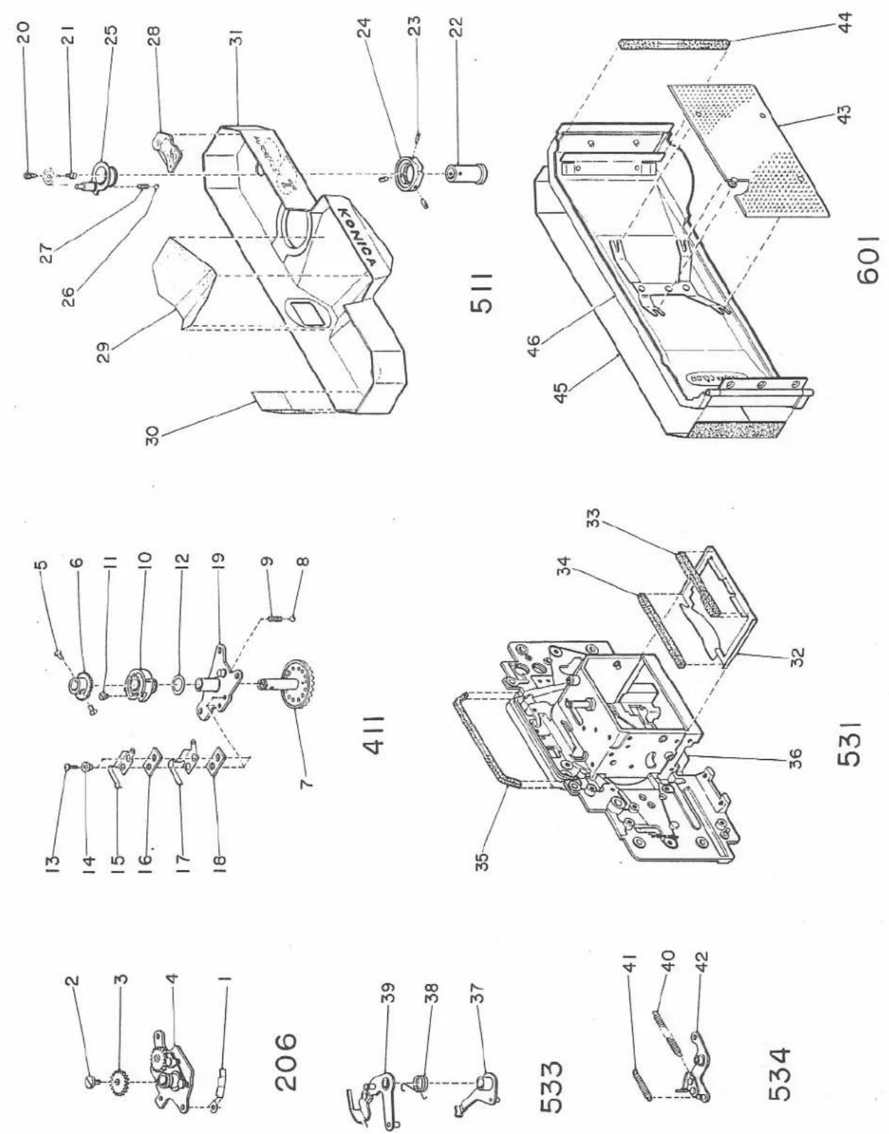
G
H
natural_image
Technical line drawing of a mechanical assembly with gears and housing (no text or symbols)Lists of tools
專用工具
| Tool No.工具番号 | Tool Name工具名称 | Name of the parts for which the tool is to be used部品名称(用途) | Parts No.部番 |
| 1-1 | Special screw driverカニ目ドライバー | Nut for setting top coverファインダーカバー止めナット | 05111 |
| 1-2 | Pin releasing lock-leverロックレバー解除用ピン | Film counter sub-assembly指数器 | 231 |
| 1-3 | Special screw driverカニ目ドライバー | Synchro socket sub-assemblyシンクロソケット | 111 |
| 1-4 | Special screw driverカニ目ドライバー | Set screw for self-timer leverセルフレバー止めネジ | 05385 |
| 1-5 | Special screw driverカニ目ドライバー | Set screw for shutter dialシャッター数値板取付ネジ | 04105 |
| 1-6 | Special screw driverカニ目ドライバー | Nut for setting regulating plate調整板止めナット | 08057 |
| 1-7 | Set jig for top screw止めネジ締付治具 | Top screw for wind lever巻上げレバー止めネジ | 02005 |
| 1-8 | Tool for spring setバネ掛け工具 | Recoiling spring for winding巻上げ軸復元バネ | 02017 |
| 1-9 | Wind lever仮巻上げレバー | For charging the film and shutter仮巻上げ用 | |
| 1-10 | Shank for special screwdriver ドライバー用柄 | For special screw driverカニ目ドライバー用 |
natural_image
Line drawing of a mechanical tool with a circular head and connecting rod (no text or symbols)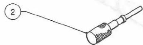
natural_image
Simple line drawing of a connector with a numbered label (2) and no text or symbols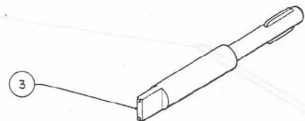
natural_image
Simple line drawing of a pen-like tool with a numbered label (3) pointing to its tip, no text or symbols present.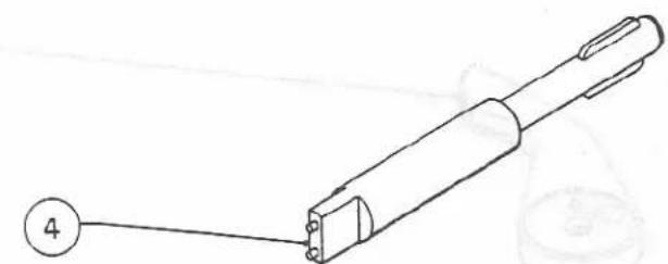
natural_image
Line drawing of a mechanical tool with a numbered label (4) pointing to its end, no text or symbols present.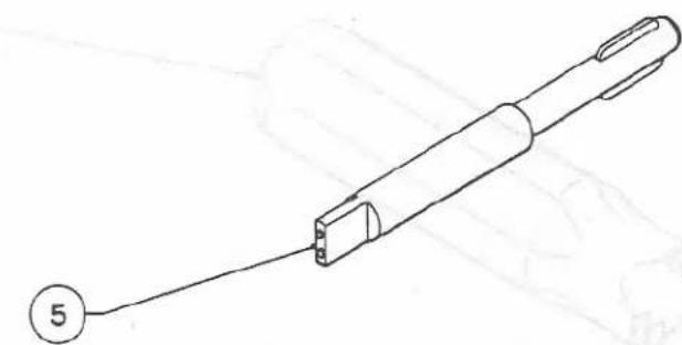
natural_image
Line drawing of a pen-like tool with a circular marker labeled '5' pointing to its end (no text or symbols on the object itself)LIST OF PARTS TO BE SUPPLIED FOR KONICA AUTO REFLEX T-Ⅱ
コニカ ニュー FTA 支給部品一覧表
| Parts No.部品番号 | Sub-assembly No.部組番号 | Parts No.部品番号 | Sub-assembly No.部組番号 | Parts No.部品番号 | Sub-assembly No.部組番号 | |
| × | 01001 | 101 | 02021 | × 02057 | ||
| 01002 | × 02022 | 201 | × 02058 | 207 | ||
| 01003 | × 02023 | 201 | × 02060 | 209 | ||
| 01004 | × 02024 | 201 | × 02062 | 101 | ||
| 01006 | 02025 | 02064 | ||||
| 01008 | × 02026 | 201 | 02065 | |||
| 01013 | × 02027 | 203 | × 02067 | 203 | ||
| 01015 | 02028 | 02068 | ||||
| 01016 | × 02029 | 203 | 02069 | |||
| × | 01009 | 101 | 02030 | 02070 | ||
| 02031 | × 02075 | |||||
| × | 01102 | 111 | 02032 | × 02076 | ||
| × | 01103 | 111 | × 02033 | 207 | × 02077 | 201 |
| × | 01104 | 111 | 02034 | |||
| × | 01105 | 111 | × 02035 | 208 | 02201 | |
| × 02036 | 206 | × 02202 | 221 | |||
| 02001 | × 02037 | 206 | 02203 | |||
| × | 02002 | 201 | × 02038 | 206 | 02204 | |
| × | 02003 | 206 | × 02039 | 206 | 02205 | |
| 02004 | × 02041 | 206 | 02206 | |||
| 02005 | × 02042 | 206 | 02207 | |||
| 02006 | × 02043 | 206 | 02208 | |||
| 02007 | × 02044 | 206 | 02209 | |||
| 02011 | × 02045 | 206 | × 02210 | 221 | ||
| 02012 | × 02046 | 206 | ||||
| 02013 | × 02047 | 206 | × 02301 | 231 | ||
| 02014 | × 02050 | 209 | × 02302 | 231 | ||
| 02015 | × 02051 | 209 | × 02303 | 231 | ||
| × | 02016 | 201 | 02052 | × 02304 | ||
| 02017 | 02053 | 02305 | ||||
| 02018 | × 02054 | 208 | × 02306 | 231 | ||
| 02019 | 02055 | 210 | × 02307 | |||
| 02020 | 02056 | 210 | × 02308 | |||
LIST OF PARTS TO BE SUPPLIED FOR KONICA AUTO REFLEX T-Ⅱ
コニカ ニュー FTA 支給部品一覧表
| Parts No.部品番号 | Sub-assembly No.部組番号 | Parts No.部品番号 | Sub-assembly No.部組番号 | Parts No.部品番号 | Sub-assembly No.部組番号 |
| 0 2 3 0 9 | 231 | 0 3 0 1 0 | 531 | 0 4 1 1 3 | 411 |
| 0 2 3 1 0 | 231 | 0 3 0 1 1 | 0 4 1 1 4 | 411 | |
| 0 2 3 1 1 | 231 | 0 3 0 1 2 | 511 | 0 4 1 1 9 | 511 |
| 0 2 3 1 2 | 231 | 0 3 0 1 3 | 511 | 0 4 1 2 2 | 411 |
| 0 2 3 1 3 | 231 | 0 3 0 1 4 | 511 | 0 4 1 2 3 | 411 |
| 0 2 3 1 4 | 231 | 0 3 0 1 5 | 511 | 0 4 1 2 4 | 411 |
| 0 2 3 1 5 | 231 | 0 3 0 1 8 | 301 | 0 4 1 2 5 | 411 |
| 0 2 3 1 6 | 231 | 0 3 0 1 9 | 301 | 0 4 1 2 7 | 411 |
| 0 2 3 1 7 | 231 | 0 3 0 2 0 | 301 | 0 4 1 2 8 | 414 |
| 0 2 3 1 8 | 231 | 0 3 0 2 2 | 231 | 0 4 1 3 3 | 411 |
| 0 2 3 2 2 | 0 3 0 2 3 | 231 | 0 4 1 3 4 | 414 | |
| 0 3 0 2 4 | 231 | 0 4 1 3 5 | 414 | ||
| 0 2 4 0 1 | 0 3 0 2 5 | 231 | 0 4 1 3 6 | 411 | |
| 0 2 4 0 2 | 101 | 0 3 0 2 6 | 511 | 0 4 1 3 7 | 411 |
| 0 2 4 0 3 | 241 | 0 3 0 2 7 | |||
| 0 2 4 0 4 | 241 | 0 3 0 2 8 | 511 | 0 5 1 0 1 | 511 |
| 0 2 4 0 5 | 241 | 0 3 0 2 9 | 206 | 0 5 1 0 2 | 511 |
| 0 2 4 0 7 | 241 | 0 5 1 0 3 | 511 | ||
| 0 2 4 0 8 | 0 4 0 0 2 | 0 5 1 0 4 | 511 | ||
| 0 2 4 0 9 | 0 4 0 0 3 | 0 5 1 1 1 | |||
| 0 2 4 1 0 | 241 | 0 4 0 0 4 | 402 | ||
| 0 2 4 1 1 | 241 | 0 5 2 0 1 | 521 | ||
| 0 2 4 1 2 | 241 | 0 4 1 0 1 | 414 | 0 5 2 0 2 | 521 |
| 0 4 1 0 3 | 414 | 0 5 2 0 3 | 521 | ||
| 0 3 0 0 1 | 511 | 0 4 1 0 4 | 0 5 2 0 4 | 521 | |
| 0 3 0 0 2 | 511 | 0 4 1 0 5 | 0 5 2 0 5 | 521 | |
| 0 3 0 0 3 | 301 | 0 4 1 0 6 | 415 | 0 5 2 0 6 | 521 |
| 0 3 0 0 4 | 511 | 0 4 1 0 7 | 415 | 0 5 2 0 7 | 528 |
| 0 3 0 0 5 | 301 | 0 4 1 0 8 | 0 5 2 0 8 | 528 | |
| 0 3 0 0 6 | 301 | 0 4 1 0 9 | 0 5 2 0 9 | 528 | |
| 0 3 0 0 7 | 0 4 1 1 0 | 411 | 0 5 2 1 0 | 528 | |
| 0 3 0 0 8 | 0 4 1 1 1 | 414 | 0 5 2 1 1 | 528 | |
| 0 3 0 0 9 | 0 4 1 1 2 | 511 | 0 5 2 1 2 | 528 |
LIST OF PARTS TO BE SUPPLIED FOR KONICA AUTO REFLEX T-Ⅱ
コニカ ニュー FTA 支給部品一覧表
| Parts No.部品番号 | Sub-assembly No.部組番号 | Parts No.部品番号 | Sub-assembly No.部組番号 | Parts No.部品番号 | Sub-assembly No.部組番号 | |
| × | 05213 | 528 | × 05315 | 592 | × 05349 | 534 |
| 05214 | × 05316 | 539 | × 05350 | 534 | ||
| × | 05215 | 05317 | × 05352 | 534 | ||
| × | 05216 | 525 | 05318 | × 05354 | 531 | |
| × | 05217 | 511 | 05319 | 05356 | 534 | |
| × | 05218 | 521 | × 05320 | 539 | 05357 | 534 |
| 05219 | 05321 | × 05358 | 533 | |||
| 05220 | 521 | × 05322 | 593 | 05359 | ||
| 05221 | 528 | 05323 | 05360 | |||
| 05222 | 528 | 05324 | × 05361 | 535 | ||
| 05223 | × 05325 | 533 | 05362 | |||
| 05224 | × 05326 | 537 | 05363 | |||
| × | 05226 | 525 | × 05327 | 534 | × 05364 | 535 |
| × | 05227 | 528 | × 05328 | 537 | 05365 | |
| × | 05229 | 525 | × 05329 | 539 | 05366 | |
| 05230 | 05330 | 05367 | ||||
| 05231 | × 05331 | 531 | × 05368 | 593 | ||
| × | 05232 | 521 | 05332 | 531 | 05369 | |
| 05333 | 537 | 05370 | ||||
| × | 05301 | 531 | 05335 | 05371 | ||
| × | 05302 | 531 | × 05336 | 533 | × 05372 | 536 |
| × | 05303 | 537 | × 05337 | 533 | × 05373 | 596 |
| × | 05304 | 534 | 05338 | × 05374 | 596 | |
| × | 05305 | 537 | × 05339 | 531 | × 05375 | 596 |
| 05306 | × 05340 | 531 | × 05376 | 591 | ||
| × | 05307 | 537 | × 05341 | 533 | × 05377 | 596 |
| × | 05308 | 531 | × 05342 | 533 | × 05378 | 591 |
| × | 05309 | 537 | × 05343 | 533 | 05379 | |
| × | 05310 | 537 | × 05344 | 533 | 05380 | |
| × | 05311 | 531 | 05345 | × 05381 | 595 | |
| 05312 | × 05346 | 533 | × 05383 | 598 | ||
| × | 05313 | 537 | 05347 | × 05384 | 598 | |
| × | 05314 | 593 | × 05348 | 533 | 05385 | |
LIST OF PARTS TO BE SUPPLIED FOR KONICA AUTOREFLEX T-Ⅱ
コニカ ニュー FTA 支給部品一覧表
| Parts No.部品番号 | Sub-assembly No.部組番号 | Parts No.部品番号 | Sub-assembly No.部組番号 | Parts No.部品番号 | Sub-assembly No.部組番号 |
| × 05386 | 538 | × 05502 | 531 | × 08004 | 809 |
| × 05387 | 538 | × 05503 | 551 | × 08005 | 301 |
| × 05388 | 536 | × 05504 | 551 | 08006 | |
| 05389 | 05505 | 08007 | |||
| × 05390 | 538 | 05506 | 08008 | ||
| × 05391 | 532 | × 08009 | 811 | ||
| × 05392 | 591 | × 06001 | 601 | 08011 | |
| × 05393 | 532 | × 06002 | 601 | 08012 | |
| × 05394 | 595 | × 06003 | 601 | × 08013 | 801 |
| × 05395 | 521 | × 06004 | 601 | × 08014 | 801 |
| 05396 | × 06005 | 601 | 08015 | ||
| 05397 | 06010 | 601 | × 08016 | 801 | |
| 05398 | 06011 | 601 | 08017 | ||
| 05399 | × 06013 | 601 | × 08018 | ||
| × 06014 | 601 | 08019 | |||
| × 05401 | 541 | 06015 | 08020 | ||
| × 05402 | 541 | × 06016 | 601 | 08021 | |
| 05404 | × 06017 | 601 | 08023 | ||
| 05405 | 08024 | ||||
| 05406 | 06101 | 08025 | |||
| 05407 | 06102 | × 08026 | 802 | ||
| 05408 | 06103 | × 08027 | 802 | ||
| 05409 | 06104 | 08028 | |||
| 05410 | × 08030 | 805 | |||
| 05411 | × 06201 | 621 | × 08031 | 803 | |
| 05412 | 06202 | × 08032 | 804 | ||
| 05413 | × 06203 | 621 | × 08033 | 844 | |
| 05414 | × 06204 | 621 | 08034 | ||
| 05415 | 06205 | 531 | × 08035 | 803,807 | |
| 05416 | 08036 | ||||
| × 05417 | 541 | × 08001 | 809 | × 08037 | 805 |
| 08002 | × 08038 | 801 | |||
| × 05501 | 534 | 08003 | 08041 |
LIST OF PARTS TO BE SUPPLIED FOR KONICA AUTOREFLEX T-Ⅱ
コニカ ニュー FTA 支給部品一覧表
| Parts No.部品番号 | Sub-assembly No.部組番号 | Parts No.部品番号 | Sub-assembly No.部組番号 | Parts No.部品番号 | Sub-assembly No.部組番号 |
| × 08043 | 806 | × 08083 | 814 | × 08405 | 841 |
| × 08044 | 806 | × 08084 | 814 | × 08406 | 841 |
| 08045 | × 08086 | 812 | 08407 | 101 | |
| × 08046 | 806 | × 08088 | 521 | ||
| × 08047 | 806 | × 08089 | 813 | 91118 | 601 |
| × 08048 | 805 | × 08090 | 807 | ||
| × 08049 | 805 | 11400 | |||
| 08050 | 802 | × 08227 | 231 | 11470 | |
| × 08051 | 804 | × 08228 | 411 | 16304 | |
| 08052 | × 08229 | 411 | |||
| × 08053 | 804 | × 08230 | 411 | 23310 | |
| 08054 | × 08231 | 411 | 25290 | ||
| × 08055 | 803 | 08234 | |||
| × 08056 | 803 | 45105 | |||
| 08057 | 08301 | 45135 | |||
| × 08058 | 806 | × 08302 | 831 | 45179 | |
| × 08059 | 806 | 08303 | |||
| 08060 | × 08304 | 831 | 45209 | ||
| × 08062 | 807 | × 08305 | 831 | 45249 | |
| 08063 | × 08306 | 831 | 45289 | ||
| 08064 | 08308 | 45589 | 231 | ||
| × 08065 | 807 | 08310 | |||
| 08066 | 08311 | 51169 | 511 | ||
| × 08067 | 813 | × 08312 | 841 | ||
| × 08069 | 812 | 08313 | 51209 | 411 | |
| 08070 | × 08314 | 841 | |||
| × 08072 | 813 | 08315 | 101 | 61309 | |
| 08073 | 521, 812 | 08351 | 61344 | 411 | |
| × 08074 | 813 | ||||
| × 08075 | 812 | × 08401 | 841 | 61424 | 231 |
| 08077 | 813 | × 08402 | 841 | ||
| × 08078 | 813 | × 08403 | 841 | 61444 | |
| × 08081 | 811 | × 08404 | 841 |
LIST OF PARTS TO BE SUPPLIED FOR KONICA AUTOREFLEX T-Ⅱ
コニカ ニュー FTA 支給部品一覧表
| Parts No.部品番号 | Sub-assembly No.部組番号 | Parts No.部品番号 | Sub-assembly No.部組番号 | Parts No.部品番号 | Sub-assembly No.部組番号 |
| 61584 | 05334 | ||||
| 08202 | |||||
| 63294 | |||||
| 63315 | 411 | ||||
| 63425 | |||||
| 63429 | |||||
| 63444 | |||||
| 63474 | |||||
| 65284 | |||||
| 65395 | |||||
| 65424 | 802 | ||||
| 65464 | |||||
| 65484 | |||||
| 65575 | |||||
| 65619 | |||||
| 65625 |
LIST OF SUB-ASSEMBLY PARTS
TO BE SUPPLIED FOR KONICA AUTOREFLEX T—II
コニカ ニュー FTA 支給部組一覧表
| Sub-assembly No.部組番号 | Parts No.部品番号 | Sub-assembly No.部組番号 | Parts No.部品番号 | Sub-assembly No.部組番号 | Parts No.部品番号 |
| 1 0 1 | × 0 1 0 0 1 | × 0 2 0 4 2 | 0 2 3 1 1 | ||
| × 0 1 0 0 9 | × 0 2 0 4 3 | × 0 2 3 1 2 | |||
| × 0 2 0 6 2 | × 0 2 0 4 4 | × 0 2 3 1 3 | |||
| × 0 2 4 0 2 | × 0 2 0 4 5 | 0 2 3 1 4 | |||
| 0 8 3 1 5 | × 0 2 0 4 6 | × 0 2 3 1 5 | |||
| 0 8 4 0 7 | × 0 2 0 4 7 | × 0 2 3 1 6 | |||
| 6 1 4 2 4 | × 0 2 0 7 5 | 0 2 3 1 7 | |||
| 6 5 4 8 4 | × 0 2 3 2 2 | × 0 2 3 1 8 | |||
| × 0 3 0 2 9 | × 0 3 0 2 2 | ||||
| 1 1 1 | × 0 1 1 0 2 | × 0 3 0 2 3 | |||
| × 0 1 1 0 3 | 2 0 7 | × 0 2 0 3 3 | × 0 3 0 2 4 | ||
| × 0 1 1 0 4 | × 0 2 0 5 8 | × 0 3 0 2 5 | |||
| × 0 1 1 0 5 | × 0 8 2 2 7 | ||||
| 2 0 8 | × 0 2 0 3 5 | 4 5 5 8 9 | |||
| 2 0 1 | × 0 2 0 0 2 | × 0 2 0 5 4 | 6 1 4 2 4 | ||
| × 0 2 0 1 6 | |||||
| × 0 2 0 2 2 | 2 1 0 | 0 2 0 5 5 | 2 4 1 | × 0 2 4 0 3 | |
| × 0 2 0 2 3 | 0 2 0 5 6 | × 0 2 4 0 4 | |||
| × 0 2 0 2 4 | 0 2 0 6 4 | × 0 2 4 0 5 | |||
| × 0 2 0 2 6 | × 0 2 4 0 7 | ||||
| × 0 2 0 7 6 | 2 2 1 | × 0 2 2 0 2 | × 0 2 4 1 0 | ||
| × 0 2 0 7 7 | × 0 2 2 1 0 | × 0 2 4 1 1 | |||
| × 0 2 4 1 2 | |||||
| 2 0 3 | × 0 2 0 2 7 | 2 3 1 | × 0 2 3 0 1 | 6 5 2 8 4 | |
| × 0 2 0 2 9 | × 0 2 3 0 2 | ||||
| × 0 2 0 6 7 | × 0 2 3 0 3 | 4 0 1 | SHUTTER UNIT | ||
| × 0 2 3 0 4 | |||||
| 2 0 6 | × 0 2 0 0 3 | 0 2 3 0 5 | 4 0 2 | 0 4 0 0 4 | |
| × 0 2 0 3 6 | × 0 2 3 0 6 | × 4 0 1 | |||
| × 0 2 0 3 7 | × 0 2 3 0 7 | ||||
| × 0 2 0 3 8 | × 0 2 3 0 8 | 4 1 1 | × 0 4 1 1 0 | ||
| × 0 2 0 3 9 | × 0 2 3 0 9 | × 0 4 1 1 3 | |||
| × 0 2 0 4 1 | × 0 2 3 1 0 | × 0 4 1 1 4 |
LIST OF SUB-ASSEMBLY PARTS TO
TO BE SUPPLIED FOR KONICA AUTOREFLEX T—II
コニカ ニュー FTA 支給部組一覧表
| Sub-assembly No.部組番号 | Parts No.部品番号 | Sub-assembly No.部組番号 | Parts No.部品番号 | Sub-assembly No.部組番号 | Parts No.部品番号 |
| × 04122 | × 03015 | 528 | × 05207 | ||
| × 04123 | × 03026 | 05208 | |||
| × 04124 | × 03028 | × 05209 | |||
| × 04125 | × 04112 | × 05210 | |||
| × 04127 | × 04119 | 05211 | |||
| × 04133 | × 05101 | × 05212 | |||
| × 04136 | × 05102 | × 05213 | |||
| × 04137 | × 05103 | 05221 | |||
| × 08228 | 05104 | 05222 | |||
| × 08229 | × 05217 | × 05227 | |||
| × 08230 | 16304 | 11400 | |||
| × 08231 | 51169 | ||||
| 51209 | 531 | × 03010 | |||
| 61344 | 521 | × 05201 | × 05301 | ||
| 63315 | × 05202 | × 05308 | |||
| 05203 | × 05311 | ||||
| 414 | × 04101 | × 05204 | × 05331 | ||
| 04103 | × 05205 | 05332 | |||
| × 04111 | × 05206 | × 05354 | |||
| × 04128 | × 05218 | × 05502 | |||
| × 04134 | 05220 | 06205 | |||
| × 04135 | × 05232 | 597 | |||
| 61334 | × 08077 | ||||
| × 08088 | 532 | × 05391 | |||
| 415 | × 04106 | 65395 | × 05393 | ||
| × 04107 | 812 | ||||
| 813 | 533 | × 05325 | |||
| 511 | 03001 | 815 | × 05336 | ||
| 03002 | × 05337 | ||||
| 03004 | 525 | × 05216 | × 05341 | ||
| × 03012 | × 05226 | × 05342 | |||
| × 03013 | × 05229 | × 05343 | |||
| × 03014 | × 05344 |
LIST OF SUB-ASSEMBLY PARTS
TO BE SUPPLIED FOR KONICA AUTOREFLEX T-π
コニカ ニュー FTA 支給部組一覧表
| Sub-assembly No.部組番号 | Parts No.部品番号 | Sub-assembly No.部組番号 | Parts No.部品番号 | Sub-assembly No.部組番号 | Parts No.部品番号 |
| × 05346 | 541 | × 05401 | 601 | × 06001 | |
| × 05348 | × 05402 | × 06002 | |||
| × 05358 | × 05417 | × 06003 | |||
| 61309 | × 06004 | ||||
| 534 | × 05304 | × 06005 | |||
| × 05327 | 551 | × 05503 | 06010 | ||
| × 05349 | × 05504 | 06011 | |||
| × 05350 | × 06013 | ||||
| × 05352 | 591 | × 05376 | × 06014 | ||
| 05356 | × 05378 | × 06016 | |||
| 05357 | × 05392 | × 06017 | |||
| × 05501 | 91118 | ||||
| 535 | × 05361 | 592 | × 05315 | ||
| × 05364 | × 05322 | 609 | × 06002 | ||
| 593 | × 05314 | × 06004 | |||
| 536 | × 05372 | × 05322 | 621 | × 06201 | |
| × 05388 | × 05368 | × 06203 | |||
| 537 | × 05303 | 595 | × 05381 | × 06204 | |
| × 05305 | × 05394 | 801 | × 08013 | ||
| × 05307 | × 08014 | ||||
| × 05309 | 596 | × 05373 | × 08016 | ||
| × 05310 | × 05374 | × 08038 | |||
| × 05313 | × 05375 | ||||
| × 05326 | × 05377 | 802 | × 08026 | ||
| × 05328 | × 08027 | ||||
| 05333 | 597 | × 05302 | 08050 | ||
| × 05339 | 65424 | ||||
| 538 | × 05386 | × 05340 | |||
| × 05387 | 803 | × 08031 | |||
| × 05390 | 598 | × 05383 | × 08035 | ||
| × 05384 | × 08055 |
LIST OF SUB-ASSEMBLY PARTS
TO BE SUPPLIED FOR KONICA AUTOREFLEX T-II
コニカ ニュー FTA 支給部組一覧表
| Sub-assembly No.部組番号 | Parts No.部品番号 | Sub-assembly No.部組番号 | Parts No.部品番号 | Sub-assembly No.部組番号 | Parts No.部品番号 |
| × 0805661444 | × 08073× 08086 | 301 | × 03003× 03005× 03006 | ||
| 804 | × 08032× 08033× 08051× 08053 | 813 | × 08067× 08074× 08075× 08078× 08089 | 209 | × 03018× 08005 |
| 805 | × 08030× 08037× 08048× 08049 | 815 | × 08083× 08084 | × 02050× 02051× 02057× 02060 | |
| 806 | × 08043× 08044× 08046× 08047× 08058× 08059 | 821 | METERUNIT | ||
| 807 | × 08035× 08062× 08065× 08090 | 841 | × 08302× 08304× 08305× 08306 | ||
| 809 | × 08001× 08004 | × 08401× 08402× 08403× 08404× 08405 | |||
| 811 | × 08009× 08081 | 539 | × 08406× 08312× 08313 | ||
| 812 | × 08069× 08072 | × 05320× 05329× 08316 |
Parts index for FTAII camera
FTA IIカメラ部品索引
| Parts No.部 番 | Sheet No.シート No. | Parts No.部 番 | Sheet No.シート No. | Parts No.部 番 | Sheet No.シート No. |
| 0 1 0 0 1 | C-63 (101) | 0 2 0 1 4 | C-4 8 | F-4(☆02036) | |
| 0 1 0 0 2 | A- 4 | 0 2 0 1 5 | C-4 1 | 0 2 0 4 1 | C-15 (206) |
| 0 1 0 0 3 | A- 3 | 0 2 0 1 6 | C-12 (201) | F-3 | |
| 0 1 0 0 4 | C-5 4 | 0 2 0 1 7 | C- 9 | 0 2 0 4 2 | C-15 (206) |
| 0 1 0 0 6 | C-5 9 | 0 2 0 1 8 | C- 8 | F-4(☆02036) | |
| 0 1 0 0 8 | C-6 0 | 0 2 0 1 9 | C-4 6 | 0 2 0 4 3 | C-15 (206) |
| 0 1 0 1 3 | C-5 2 | 0 2 0 2 0 | C-1 3 | F-2 | |
| 0 1 0 1 5 | C-5 3 | 0 2 0 2 1 | C- 7 | 0 2 0 4 4 | C-15 (206) |
| 0 1 0 1 6 | C-6 2 | 0 2 0 2 2 | C-12 (201) | F-4(☆02036) | |
| 0 2 0 2 3 | C-12 (201) | 0 2 0 4 5 | C-15 (206) | ||
| 0 2 0 2 4 | C-12 (201) | F-4(☆02036) | |||
| 0 2 0 2 5 | C-5 1 | 0 2 0 4 6 | C-15 (206) | ||
| 0 1 1 0 2 | D-35 (111) | E-6 8 | F-4(☆02036) | ||
| 0 1 1 0 3 | D-35 (111) | 0 2 0 2 6 | C-12 (201) | 0 2 0 4 7 | C-15 (206) |
| 0 1 1 0 4 | D-35 (111) | 0 2 0 2 7 | C-2 0 | F-4(☆02036) | |
| 0 1 1 0 5 | D-35 (111) | 0 2 0 2 8 | C-1 7 | 0 2 0 5 0 | C-36 (209) |
| 0 2 0 2 9 | C-2 2 | 0 2 0 5 1 | C-36 (209) | ||
| 0 2 0 3 0 | C- 7 | 0 2 0 5 2 | C-3 5 | ||
| 0 2 0 3 1 | C-1 6 | 0 2 0 5 3 | C-3 3 | ||
| 0 2 0 0 1 | A-3 7 | 0 2 0 3 2 | C- 2 | 0 2 0 5 4 | C-42 (208) |
| 0 2 0 0 2 | C-12 (201) | 0 2 0 3 3 | C-4 (207) | 0 2 0 5 5 | C-3 8 |
| 0 2 0 0 3 | C-15 (206) | 0 2 0 3 4 | C- 5 | 0 2 0 5 6 | C-3 9 |
| F-4(☆02036) | 0 2 0 3 5 | C-42 (208) | 0 2 0 5 7 | C-36 (209) | |
| 0 2 0 0 4 | C-1 1 | 0 2 0 3 6 | C-15 (206) | 0 2 0 5 8 | C-4 (207) |
| 0 2 0 0 5 | A-3 5 | F-4(☆02036) | 0 2 0 6 0 | C-36 (209) | |
| 0 2 0 0 6 | A-3 6 | 0 2 0 3 7 | C-15 (206) | 0 2 0 6 2 | C-63 (101) |
| 0 2 0 0 7 | A-3 8 | F-4(☆02036) | 0 2 0 6 4 | C-4 0 | |
| 0 2 0 1 1 | C- 6 | 0 2 0 3 8 | C-15 (206) | 0 2 0 6 5 | C-5 0 |
| 0 2 0 1 2 | C- 3 | F-4(☆02036) | 0 2 0 6 7 | C-1 9 | |
| 0 2 0 1 3 | C-4 7 | 0 2 0 3 9 | C-18 (206) | 0 2 0 6 8 | C-2 1 |
| 0 2 0 6 9 | C-1 8 | 0 2 3 0 9 | B-67 (231) | F-2 2 | |
| 0 2 0 7 0 | C-4 9 | 0 2 3 1 0 | B-67 (231) | 0 3 0 0 2 | A-40 (511) |
| 0 2 0 7 5 | C-15 (206) | 0 2 3 1 1 | B-67 (231) | F-2 4 | |
| F-1 | 0 2 3 1 2 | B-67 (231) | 0 3 0 0 3 | E-4 (301) | |
| 0 2 0 7 6 | C-12 (201) | 0 2 3 1 3 | B-67 (231) | 0 3 0 0 4 | E-40 (511) |
| 0 2 0 7 7 | C-12 (201) | 0 2 3 1 4 | B-67 (231) | F-2 0 | |
| 0 2 3 1 5 | B-67 (231) | 0 3 0 0 5 | E-4 (301) | ||
| 0 2 3 1 6 | B-67 (231) | 0 3 0 0 6 | E-4 (301) | ||
| 0 2 3 1 7 | B-67 (231) | 0 3 0 0 7 | C-4 5 | ||
| 0 2 2 0 1 | C-3 2 | 0 2 3 1 8 | B-67 (231) | 0 3 0 0 8 | C-4 3 |
| 0 2 2 0 2 | C--30 (221) | 0 2 3 2 2 | C-15 (206) | 0 3 0 0 9 | C-4 4 |
| 0 2 2 0 3 | C-3 1 | F-4(☆02036) | 0 3 0 1 0 | E-80 (531) | |
| 0 2 2 0 4 | C-2 9 | F-36 (☆05301) | |||
| 0 2 2 0 5 | C-2 8 | 0 3 0 1 1 | E-1 | ||
| 0 2 2 0 6 | C-2 5 | 0 3 0 1 2 | A-40 (511) | ||
| 0 2 2 0 7 | C-2 3 | 0 2 4 0 1 | A-1 2 | F-2 5 | |
| 0 2 2 0 8 | C-2 4 | 0 2 4 0 2 | C-63 (101) | 0 3 0 1 3 | A-40 (511) |
| 0 2 2 0 9 | C-2 7 | 0 2 4 0 3 | A-1 1 | F-31 (☆05101) | |
| 0 2 2 1 0 | C-30 (221) | 0 2 4 0 4 | A-1 8 | 0 3 0 1 4 | A-40 (511) |
| 0 2 4 0 5 | A-2 0 | F-2 5 | |||
| 0 2 4 0 7 | A-1 6 | 0 3 0 1 5 | A-40 (511) | ||
| 0 2 4 0 8 | A-1 4 | F-2 7 | |||
| 0 2 3 0 1 | B-67 (231) | 0 2 4 0 9 | A-1 3 | 0 3 0 1 8 | E-4 (301) |
| 0 2 3 0 2 | B-67 (231) | 0 2 4 1 0 | A-1 0 | 0 3 0 1 9 | E-4 (301) |
| 0 2 3 0 3 | B-67 (231) | 0 2 4 1 1 | A-1 7 | 0 3 0 2 0 | E-4 (301) |
| 0 2 3 0 4 | B-67 (231) | 0 2 4 1 2 | A-1 9 | 0 3 0 2 2 | B-67 (231) |
| 0 2 3 0 5 | B-67 (231) | 0 3 0 2 3 | B-67 (231) | ||
| 0 2 3 0 6 | B-67 (231) | 0 3 0 2 4 | B-67 (231) | ||
| 0 2 3 0 7 | B-67 (231) | 0 3 0 2 5 | B-67 (231) | ||
| 0 2 3 0 8 | B-67 (231) | 0 3 0 0 1 | A-40 (511) | 0 3 0 2 6 | A-40 (511) |
| 0 2 0 7 6 | C-12 (201) | 0 2 3 1 3 | B-67 (231) | 0 3 0 0 4 | E-40 (511) |
| 0 2 0 7 7 | C-12 (201) | 0 2 3 1 4 | B-67 (231) | F-2 0 | |
| 0 2 3 1 5 | B-67 (231) | 0 3 0 0 5 | E-4 (301) | ||
| 0 2 3 1 6 | B-67 (231) | 0 3 0 0 6 | E-4 (301) | ||
| 0 2 3 1 7 | B-67 (231) | 0 3 0 0 7 | C-4 5 | ||
| 0 2 2 0 1 | C-3 2 | 0 2 3 1 8 | B-67 (231) | 0 3 0 0 8 | C-4 3 |
| 0 2 2 0 2 | C--30 (221) | 0 2 3 2 2 | C-15 (206) | 0 3 0 0 9 | C-4 4 |
| 0 2 2 0 3 | C-3 1 | F-4(☆02036) | 0 3 0 1 0 | E-80 (531) | |
| 0 2 2 0 4 | C-2 9 | F-36 (☆05301) | |||
| 0 2 2 0 5 | C-2 8 | 0 3 0 1 1 | E-1 | ||
| 0 2 2 0 6 | C-2 5 | 0 3 0 1 2 | A-40 (511) | ||
| 0 2 2 0 7 | C-2 3 | 0 2 4 0 1 | A-1 2 | F-2 5 | |
| 0 2 2 0 8 | C-2 4 | 0 2 4 0 2 | C-63 (101) | 0 3 0 1 3 | A-40 (511) |
| 0 2 2 0 9 | C-2 7 | 0 2 4 0 3 | A-1 1 | F-31 (☆05101) | |
| 0 2 2 1 0 | C-30 (221) | 0 2 4 0 4 | A-1 8 | 0 3 0 1 4 | A-40 (511) |
| 0 2 4 0 5 | A-2 0 | F-2 5 | |||
| 0 2 4 0 7 | A-1 6 | 0 3 0 1 5 | A-40 (511) | ||
| 0 2 4 0 8 | A-1 4 | F-2 7 | |||
| 0 2 3 0 1 | B-67 (231) | 0 2 4 0 9 | A-1 3 | 0 3 0 1 8 | E-4 (301) |
| 0 2 3 0 2 | B-67 (231) | 0 2 4 1 0 | A-1 0 | 0 3 0 1 9 | E-4 (301) |
| 0 2 3 0 3 | B-67 (231) | 0 2 4 1 1 | A-1 7 | 0 3 0 2 0 | E-4 (301) |
| 0 2 3 0 4 | B-67 (231) | 0 2 4 1 2 | A-1 9 | 0 3 0 2 2 | B-67 (231) |
| 0 2 3 0 5 | B-67 (231) | 0 3 0 2 3 | B-67 (231) | ||
| 0 2 3 0 6 | B-67 (231) | 0 3 0 2 4 | B-67 (231) | ||
| 0 2 3 0 7 | B-67 (231) | 0 3 0 2 5 | B-67 (231) | ||
| 0 2 3 0 8 | B-67 (231)F-31(☆05101) | 0 3 0 0 1 | A-40 (511)F-1 0 | 0 3 0 2 6 | A-40 (511)F-2 9 |
| 0 3 0 2 7 | E- 3 | 0 4 1 1 4 | B-3 (411) | 0 5 1 0 3 | A-40 (511) |
| E-2 4 | F-1 2 | F-3 0 | |||
| 0 3 0 2 8 | A-40 (511) | 0 4 1 1 9 | A-40 (511) | 0 5 1 0 4 | A-40 (511) |
| F-2 1 | F-31(☆05101) | F-2 8 | |||
| 0 3 0 2 9 | C-15 (206) | 0 4 1 2 2 | B-3 (411) | 0 5 1 1 1 | A-3 9 |
| F-4(☆02036) | F-19(☆04122) | ||||
| 0 4 1 2 3 | B-3 (411) | ||||
| F-7(☆04133) | |||||
| 0 4 1 2 4 | B-3 (411) | 0 5 2 0 1 | B-1 7 | ||
| 0 4 0 0 2 | B-2 9 | F-19(☆04122) | 0 5 2 0 2 | B-13(☆05203) | |
| 0 4 0 0 3 | B-3 0 | 0 4 1 2 5 | B-3 (411) | 0 5 2 0 3 | B-13(☆05203) |
| 0 4 0 0 4 | B-31 (402) | F-19(☆04122) | 0 5 2 0 4 | B-13(☆05203) | |
| 0 4 1 2 7 | B-3 (411) | 0 5 2 0 5 | B-13(☆05203) | ||
| F- 9 | 0 5 2 0 6 | B-1 1 | |||
| 0 4 1 2 8 | A-3 3 | 0 5 2 0 7 | D- 5 | ||
| 0 4 1 0 1 | A-2 8 | 0 4 1 3 3 | B-3 (411) | 0 5 2 0 8 | D-1 4 |
| 0 4 1 0 3 | A-2 9 | F-7(☆04133) | 0 5 2 0 9 | D-1 2 | |
| 0 4 1 0 4 | A-2 2 | 0 4 1 3 4 | A-3 4 | 0 5 2 1 0 | D-1 3 |
| 0 4 1 0 5 | A-2 1 | 0 4 1 3 5 | A-3 1 | 0 5 2 1 1 | D- 9 |
| 0 4 1 0 6 | A-2 3 | 0 4 1 3 6 | B-3 (411) | 0 5 2 1 2 | D-1 1 |
| 0 4 1 0 7 | A-2 4 | F-1 1 | 0 5 2 1 3 | D- 7 | |
| 0 4 1 0 8 | A-2 6 | 0 4 1 3 7 | B-3 (411) | 0 5 2 1 4 | B- 8 |
| 0 4 1 0 9 | A-2 7 | F-1 2 | 0 5 2 1 5 | B-8(☆05214) | |
| 0 4 1 1 0 | B-3 (411) | 0 5 2 1 6 | A- 4 1 | ||
| F- 6 | 0 5 2 1 7 | A-40 (511) | |||
| 0 4 1 1 1 | A-3 0 | F-31(☆05101) | |||
| 0 4 1 1 2 | A-40 (511) | 0 5 1 0 1 | A-40 (511) | 0 5 2 1 8 | B-1 0 |
| F-31(☆05101) | F-31(☆05101) | 0 5 2 1 9 | B-1 5 | ||
| 0 4 1 1 3 | B-3 (411) | 0 5 1 0 2 | A-40 (511) | 0 5 2 2 0 | B-13(☆05203) |
| 0 5 2 2 1 | D-8 | 0 5 3 1 3 | E-75 (537) | 0 5 3 3 6 | E-18 (533) |
| 0 5 2 2 2 | D-1 0 | 0 5 3 1 4 | E-10 (593) | F-39 (☆05344) | |
| 0 5 2 2 3 | B-9 | 0 5 3 1 5 | E-45 (592) | 0 5 3 3 7 | E-18 (533) |
| 0 5 2 2 4 | B-7 | 0 5 3 1 6 | E-77 (539) | F-39 (☆05344) | |
| 0 5 2 2 6 | A-4 2 | 0 5 3 1 7 | E-9 | 0 5 3 3 8 | E-7 2 |
| 0 5 2 2 7 | D-1 5 | 0 5 3 1 8 | E-4 7 | 0 5 3 3 9 | E-80 (531) |
| 0 5 2 2 9 | A-4 3 | E-6 9 | F-3 3 | ||
| 0 5 2 3 0 | D-4 5 | 0 5 3 1 9 | E-1 9 | 0 5 3 4 0 | E-80 (531) |
| 0 5 2 3 1 | D-4 | E-4 4 | F-3 4 | ||
| 0 5 2 3 2 | B-2 5 | 0 5 3 2 0 | E-77 (539) | 0 5 3 4 1 | E-18 (533) |
| 0 5 3 2 1 | E-4 2 | F-37 (☆05341) | |||
| 0 5 3 2 2 | E-10 (593) | 0 5 3 4 2 | E-18 (533) | ||
| E-45 (592) | F-37 (☆05341) | ||||
| 0 5 3 0 1 | E-80 (531) | 0 5 3 2 3 | E-4 3 | 0 5 3 4 3 | E-18 (533) |
| F-36 (☆05301) | 0 5 3 2 4 | E-7 3 | F-37 (☆05341) | ||
| 0 5 3 0 2 | E-80 (531) | 0 5 3 2 5 | E-18 (533) | 0 5 3 4 4 | E-18 (533) |
| F-3 2 | E-39 (☆05344) | F-39 (☆05344) | |||
| 0 5 3 0 3 | E-75 (537) | 0 5 3 2 6 | E-75 (537) | 0 5 3 4 5 | D-4 4 |
| 0 5 3 0 4 | E-17 (534) | 0 5 3 2 7 | E-17 (534) | 0 5 3 4 6 | E-18 (533) |
| F-42 (☆05349) | F-42 (☆05349) | F-39 (☆05344) | |||
| 0 5 3 0 5 | E-75 (537) | 0 5 3 2 8 | E-73 (537) | 0 5 3 4 7 | E-2 0 |
| 0 5 3 0 6 | E-8 | 0 5 3 2 9 | E-77 (539) | 0 5 3 4 8 | E-18 (533) |
| 0 5 3 0 7 | E-75 (537) | 0 5 3 3 0 | E-1 6 | F-39 (☆05344) | |
| 0 5 3 0 8 | E-80 (531) | 0 5 3 3 1 | E-80 (531) | 0 5 3 4 9 | E-17 (534) |
| F-36 (☆05301) | F-36 (☆05301) | F-42 (☆05349) | |||
| 0 5 3 0 9 | E-75 (537) | 0 5 3 3 2 | E-80 (531) | 0 5 3 5 0 | E-17 (534) |
| 0 5 3 1 0 | E-75 (537) | F-36 (☆05301) | F-42 (☆05349) | ||
| 0 5 3 1 1 | E-80 (531) | 0 5 3 3 3 | E-75 (537) | 0 5 3 5 2 | E-17 (534) |
| F-36(☆05301) | 0 5 3 3 5 | E-1 1 | E-42 (☆05349) | ||
| 0 5 3 1 2 | E-5 0 | E-4 6 | |||
| 0 5 3 5 4 | E-80 (531) | 0 5 3 8 1 | E-25 (595) | 0 5 4 1 1 | D-2 1 |
| F-36(☆05301) | 0 5 3 8 3 | D-34 (598) | 0 5 4 1 2 | D-2 1 | |
| 0 5 3 5 6 | E-17 (534) | 0 5 3 8 4 | D-34 (598) | 0 5 4 1 3 | D-21、E-71 |
| F-4 0 | 0 5 3 8 5 | D-3 2 | 0 5 4 1 4 | D-21、E-71 | |
| 0 5 3 5 7 | E-17 (534) | 0 5 3 8 6 | D-24 (538) | 0 5 4 1 5 | D-2 1 |
| F-4 1 | 0 5 3 8 7 | D-24 (538) | 0 5 4 1 6 | D-2 1 | |
| 0 5 3 5 8 | E-18 (533) | 0 5 3 8 8 | E-2 1 | 0 5 4 1 7 | D-2 0 |
| F-3 8 | 0 5 3 8 9 | A-5 | |||
| 0 5 3 5 9 | E-2 9 | 0 5 3 9 0 | D-24 (538) | ||
| 0 5 3 6 0 | E-5 1 | 0 5 3 9 1 | E-32 (532) | ||
| 0 5 3 6 1 | E-7 (535) | 0 5 3 9 2 | E-41 (591) | 0 5 5 0 1 | E-17 (534) |
| 0 5 3 6 2 | E-6 | 0 5 3 9 3 | E-32 (532) | F-42(☆05349) | |
| 0 5 3 6 3 | E-7 9 | 0 5 3 9 4 | E-25 (595) | 0 5 5 0 2 | E-80 (531) |
| 0 5 3 6 4 | E-7 (535) | 0 5 3 9 5 | E-3 0 | F-36(☆05301) | |
| 0 5 3 6 5 | E-2 6 | 0 5 3 9 6 | E-5 | 0 5 5 0 3 | E-14 (551) |
| 0 5 3 6 6 | E-3 7 | 0 5 3 9 7 | E-2 8 | 0 5 5 0 4 | E-14 (551) |
| 0 5 3 6 7 | E-2 3 | 0 5 3 9 8 | E-4 8 | 0 5 5 0 5 | E-1 2 |
| 0 5 3 6 8 | E-10 (593) | 0 5 3 9 9 | E-3 1 | 0 5 5 0 6 | E-1 3 |
| 0 5 3 6 9 | E-1 6 | ||||
| 0 5 3 7 0 | E-3 4 | ||||
| 0 5 3 7 1 | E-3 3 | ||||
| 0 5 3 7 2 | E-2 2 | 0 5 4 0 1 | D-1 7 | 0 6 0 0 1 | A-45 (601) |
| 0 5 3 7 3 | E-36 (596) | 0 5 4 0 2 | D-1 9 | F-46(☆06001) | |
| 0 5 3 7 4 | E-36 (596) | 0 5 4 0 4 | E-6 3 | 0 6 0 0 2 | A-45 (601) |
| 0 5 3 7 5 | E-36 (596) | 0 5 4 0 5 | E-6 1 | F-43(☆06002) | |
| 0 5 3 7 6 | E-41 (591) | 0 5 4 0 6 | E-6 2 | 0 6 0 0 3 | A-45 (601) |
| 0 5 3 7 7 | E-36 (596) | 0 5 4 0 7 | E-6 0 | F-46(☆06001) | |
| 0 5 3 7 8 | E-41 (591) | 0 5 4 0 8 | E-5 9 | 0 6 0 0 4 | A-45 (601) |
| 0 5 3 7 9 | E-2 7 | 0 5 4 0 9 | D-2 1 | F-43(☆06002) | |
| 0 5 3 8 0 | D-3 3F-46(☆06001) | 0 5 4 1 0 | D-2 1 | 0 6 0 0 508031 | A-45 (601)E-56 |
| 06010 | A-45 (601) | 08032 | B-57 (804) | ||
| F-46(☆06001) | 08033 | B-57 (844) | |||
| 06011 | A-45 (601) | 08001 | E-39 (809) | 08034 | B-56 |
| F-45 | 08002 | E-38 | 08035 | D-48 (807) | |
| 06013 | A-45 (601) | 08003 | E-2 | E-57 | |
| F-46(☆06001) | 08004 | E-39 (809) | 08036 | C-57 | |
| 06014 | A-45 (601) | 08005 | E-4(301) | 08037 | C-56 (805) |
| F-46(☆06001) | 08006 | D-27 | 08038 | D-37 (801) | |
| 06015 | A-44 | 08007 | D-27 | 08041 | D-28 |
| 06016 | A-45 (601) | 08008 | D-26 | 08043 | E-65 (806) |
| F-46(☆06001) | 08009 | D-31 (811) | 08044 | E-65 (806) | |
| 06017 | A-45 (601) | 08011 | D-29 | 08045 | E-64 |
| F-44 | 08012 | D-30 | 08046 | E-65 (806) | |
| 08013 | D-37 (801) | 08047 | E-65 (806) | ||
| 08014 | D-37 (801) | 08048 | C-56 (805) | ||
| 08015 | D-39 | C-58 | |||
| 06101 | B-65 | 08016 | D-37 (801) | 08049 | C-56 (805) |
| 06102 | B-63 | 08017 | D-36 | 08050 | E-67 (802) |
| 06103 | C-61 | 08018 | D-39 | 08051 | B-57 (804) |
| 06104 | B-64 | 08019 | D-27 | 08052 | E-53 |
| 08020 | D-25 | 08053 | B-57 (804) | ||
| 08021 | D-42 | 08054 | B-4 | ||
| 08023 | D-41 | 08055 | E-54 | ||
| 06201 | A-7 | 08024 | D-40 | 08056 | E-58 |
| 06202 | B-52 | 08025 | D-38 | 08057 | B-55 |
| 06203 | A-8 | 08026 | E-67 (802) | 08058 | E-65 (806) |
| 06204 | A-9 | 08027 | E-67 (802) | 08059 | E-65 (806) |
| 06205 | E-80 (531) | 08028 | E-66 | 08060 | D-37 |
| F-35 | 08030 | C-56 | 08062 | D-48 (807) | |
| 08063 | D-46 | F-14 | 08407 | B-61 | |
| 08064 | D-47 | 08231 | B-3 (411) | ||
| 08065 | D-48 (807) | F-15 | |||
| 08066 | B-53 | F-17 | |||
| 08067 | B-21 (812) | 08234 | B-2 | 91118 | A-45 (601) |
| 08069 | B-20 (812) | F-46☆05001) | |||
| 08070 | D-38 | ||||
| 08072 | B-20 (813) | ||||
| 08073 | B-20 (812) | 08301 | B-32 | ||
| B-22 | 08302 | B-36 (831) | 11400 | D-6 | |
| 08074 | B-21 (813) | 08304 | B-36 (831) | 11470 | D-3 |
| 08075 | B-20 (812) | 08305 | B-36 (831) | 16304 | A-40 |
| 08077 | B-23 | 08306 | B-36 (831) | F-23 | |
| 08078 | B-21 (813) | 08308 | B-35 | 23310 | B-41 |
| 08081 | D-31 (811). | 08310 | B-37 | 25290 | B-45 |
| 08083 | B-24 (814) | 08311 | B-38 | ||
| 08084 | B-24 (814) | 08312 | B-47 | ||
| 08086 | B-20 (812) | 08313 | B-48 | ||
| 08088 | B-14 | 08314 | B-49 | 45105 | E-76 |
| 08089 | B-21 (813) | 08315 | B-59 | 45135 | E-74 |
| 08090 | D-48 (807) | 08351 | B-33 | 45179 | C-37 |
| E-15 | |||||
| E-70 | |||||
| 45209 | C-1 | ||||
| 08227 | B-67 (231) | 08401 | B-40 | 45249 | C-26 |
| 08228 | B-3 (411) | 08402 | B-42 | 45289 | A 25 |
| F-18 | 08403 | B-43 | 45589 | B-67 (231) | |
| 08229 | B-3 (411) | 08404 | B-50 | ||
| F-16 | 08405 | B-46 | |||
| 08230 | B-3 (411) | 08406 | B-44 | ||
| 5 1 1 6 9 | A-40 (511) | 6 3 2 9 4 | D-4 3 | ||
| F-2 6 | 6 3 3 1 5 | B-3 (411) | |||
| 5 1 2 0 9 | B-3 (411) | B-6 2 | |||
| F-8 | F-5 | ||||
| 6 3 4 2 5 | C-1 0 | ||||
| 6 3 4 2 9 | A-6 | ||||
| 6 3 4 4 4 | C-5 5 | ||||
| 6 1 3 0 9 | D-1 8 | D-1 | |||
| D-2 3 | 6 3 4 7 4 | B-5 1 | |||
| 6 1 3 4 4 | A-3 2 | ||||
| B-3 (411) | |||||
| B-6 | |||||
| B-1 6 | 6 5 2 8 4 | A-1 5 | |||
| F-1 3 | 6 5 3 9 5 | B-1 8 | |||
| 6 1 4 2 4 | B-5 4 | D-2 2 | |||
| B-5 8 | E-7 8 | ||||
| B-67 (231) | 6 5 4 2 4 | B-1 2 | |||
| E-4 0 | E-3 5 | ||||
| E-4 9 | E-67 (802) | ||||
| E-5 2 | 6 5 4 6 4 | B-3 9 | |||
| 6 1 4 4 4 | B-1 | 6 5 4 8 4 | B-3 4 | ||
| B-1 9 | B-6 0 | ||||
| B-6 6 | 6 5 5 7 5 | B-2 6 | |||
| C-1 4 | 6 5 6 1 9 | D-1 6 | |||
| E-5 5 | 6 5 6 2 5 | B-2 7 | |||
| 6 1 5 8 4 | B-2 8 | ||||
| C-3 4 |
Sub-assembly index for FTA II camera
FTA II カメラ部組索引
| Sub-assembly name部組名 | Components構成部品 | Sheet No.シートNo. |
| 101 | 01001、02062(2)、02402 | C-63 |
| 111 | 01102(2)、01103(2)、01104(2)、01105(2) | C-35 |
| 201 | 02202、02016、02022(02076) | C-12 |
| 02023、02024、02026、02077 | ||
| 206 | 02003、02036、02037、02038 | C-15 |
| 02039、02041、02042、02043 | F-1~4 | |
| 02044、02045、02046(2)、02047(2) | ||
| 02075、02322、03029 | ||
| 207 | 02033、02058 | C-4 |
| 208 | 02035、02054 | C-42 |
| 209 | 02050(02051)、02057、02060 | C-36 |
| 221 | 02202、02210 | C-30 |
| 231 | 02301~02318、03022、03023 | B-67 |
| 03024、03025、08227、45589 | ||
| 61424 | ||
| 301 | 03003、03005、03006、03018 | E-4 |
| 08005 | ||
| 402 | 04004(2)、401 | B-31 |
| 411 | 04110、04113、04114、04122 | B-3 |
| 04123、04124、04125、04127 | F-5~19 | |
| 04133、04136、04137、08230(2) | ||
| 08231(2)、51209、61344(2)、63315(2) | ||
| 822、823 | ||
| 511 | 03001、03002、03004、03012 | A-40 |
| (03014)、03013(03026(2))、03015 | F-20-31 | |
| 03028、04112、04119、05101、 | ||
| 05102、05103、05104、05217 | ||
| 16304(3)、51169 | ||
| 531 | 03010、05301、05302、05308(2) | E-80 |
| 05311、05331、05332、05339 | F-32~36 | |
| 05340、05354、05502、06205 | ||
| 532 | 05391、05393 | E-32 |
| 533 | 05325、05336、05337、05341 | E-18 |
| 05342、05343、05344、05346 | F-37~39 | |
| 05348、05358 | ||
| 534 | 05304(2)、05327、05349、05350 | E-17 |
| 05352、05356、05357、05501 | F-40~42 | |
| 535 | 05361、05364(2) | E-7 |
| 537 | 05303、05305、05307、(05309(4)、05326、05328)、05310(2)、05313 | E-75 |
| 05333 | ||
| 538 | 05386、05387、05390 | D-24 |
| 539 | 05316、(05320)、05329 | E-77 |
| 551 | 05503、05504 | E-14 |
| 591 | 05376、05378、05392 | E-41 |
| 592 | 05315、05322 | E-45 |
| 593 | 05314、05322、05368 | E-10 |
| 595 | 05381、05394 | E-25 |
| 596 | 05373、05374、05375、05377 | E-36 |
| 598 | 05383、05384 | D-34 |
| 601 | 06001、06002、06003、06004(4) | A-45 |
| 06005(4)、06010(2)、06011、06013 | F-43~46 | |
| 06014、06016、06017、91118 | ||
| 801 | 08013、08014、08016、08038 | D-37 |
| 802 | 08026、08027、08050、65424 | E-67 |
| 804 | 08032、08033、08051、08053 | B-57 |
| 805 | 08030、08037、08048、08049 | C-56 |
| 806 | 08043、08044、08046、08047 | E-65 |
| 08058、08059 | ||
| 807 | 08035、08062、08065、08090 | D-48 |
| 809 | 08001、08004 | E-39 |
| 811 | 08009、08081 | D-31 |
| 812 | 08069、08072、08073、08075 | B-20 |
| 08086 | ||
| 813 | 08067、08074、08078(2)、08089 | B-21 |
| 814 | 08083、08084 | B-24 |
| 821 | Meter unit (メーターユニット) | B-6 |
| D-2 | ||
| 831 | 08302、08304、08305、08306 | B-36 |
| 501 | 07501、07502 | A-1 |
SHUTTER SERVICE MANUAL TYPE, COPAL SQUARE S.
I. Function
1) Bounding of Lead Blade and Heavy Start Action in Shutter Charging
Bounding of lead blade comes out in case pressure power by A4-11178 Shock Absorber for Blade (corresponds to S-4: Fig. No. on Technical Illustration with Parts List.) against AA4-11104 Lead Blade Sub-assembly (S-25) is weak. When the pressure power is too strong, start action in shutter setting becomes heavy.
2) Blades Wrongly Shut, Collision of Blades, Bounding of Following Blade
Make adjustment by AA4-11156 Cover Sub-assembly (S-3) so that the clearance between blade rivet head of the end of arm on AA4-11126 Following Blade Sub-assembly (S-26) and oblong projection of blade rivet head on AA4-11156 Cover Sub-assembly (S-3) will become less than 0.05 mm. In case cover projection holds down rivet head excessively, shutter start action becomes heavy when setting. Also, clearance between blades sometime widens.
3) Arrangement of B-Block (Gear position matching)
i) Bring AA4-11202 Control Cam Sub-assembly (T-24) to left rotation stop position.
ii) Match index of A4-11217 Driving Gear (T-19) with index of AA2-1124 Main Plate Sub-assembly (T-29).
iii) Mesh 2 threads of A4-11240 Set Gear B (T-6) on A4-11217 Driving Gear (T-19).
4) Arrangement of C Block (Cam position matching)
i) Bring Following Blade Release Lever of AA3-1121 Sub-plate Sub-assembly (T-15) to the maximum pushed out position by A4-11266 Following Blade Release Cam (T-22) while rotating A4-11209 Shutter Speed Setting Shaft (T-23).
11) Fit each parts of C27 \~ C22 in the directions as illustrated.
II. Performance
1) Adjustment of Blade Speed and Irregular Exposure
Blade speed adjustment is to be made by making adjustment of spring torque of A4-11171 Blade Driving Spring (S-16) through A4-11164 Ratchet wheel A (S-15): proper blade speed is 7 ± 3 ms. Blade speed changes in case there is blade squeak, oil shortage, or deformation on AA4-11602 X-lever Sub-assembly, AA4-11156 Cover Sub-assembly.
2) Adjustment of Exposure Time
i) Adjustment at 1/1 sec.
Make adjustment of spring torque of A4-11286 Main Spring (T-17) through spring adjusting ratchet B of AA3-1121 Sub-plate Sub-assembly (T-15): 900 ms - 1,000 ms is adequate.
ii) Adjustment at 1/1000 sec.
Make adjustment of the time of disengagement between Following Blade Release Lever of AA3-1121 Sub-plate Sub-assembly (T-15) and Auxiliary Arm of AA4-11126 Following Blade Sub-assembly by means of bending the hook of Following Blade Release Lever.
(Note) Rectification at 1/1000 sec. makes correction at 1/500, 1/250 unnecessary. Lead Blade Release Lever shall not be rectified in principle.
iii) Adjustment at 1/2 \~ 1/125
After adjustments of above (i) (ii), make adjustments at 1/2\~1/125 sec. Adjustment in this category is to be made by striking out or rubbing down tight Shutter Speed Cam.
3) Remedy of Irregular Action
Correct the play between Following Blade Release Lever of AA3-1121 Sub-plate Sub-assembly and Auxiliary Arm Hook of AA4-11126 Following Blade Sub-assembly to an extent of 0.1 mm - 0.2 mm at the time A4-11325 Release Lever (M-41) is hooked by AA2-11332 Hooked Cam Sub-assembly. Also, irregular action increases in case actions of AA4-11104 Lead Blade Sub-assembly (S-25) and AA4-11126 Following Blade Sub-assembly are heavy. Above modification brings down occurrence of irregular action to less than 15%.
4) Adjustment of Synchronization
i) Adjustment of M Time Lag
Adjustment is to be made by correction of transferable contact point of AA3-1162 Synchro Block Sub-assembly (M-20).
ii) Adjustment of X Time Lag
Adjustment is to be made by correction of contact section of AA4-11653 X-contact Sub-assembly (S-8)
5) Adjustment of Self-timer
Adjustment is to be so made that Timer Stop Lever of AA4-11553 Device Action Block Sub-assembly (M-31) will hold the gear not to start moving when the timer unit is set, and that the timer stop lever does not touch the gear cog ends while the timer in action, rectifying holder part of stop lever.
Please refer to the following standard procedures for assembling and adjusting of shutter.
- Process Name: Set Gear A Assembly
| Step | Procedure | Jig and/or Tool Used | Notes | Remarks | ||
| 1 | Place roller shaft in jig with the stepped side on top. | Pincettes assembly jig 411241-K1. | Refer to Fig.1 of page 26. | |||
| 2 | Apply grease (G4) to roller shaft (stepped side only). | Small brush | Very small amount. | |||
| 3 | Insert roller into shaft. | Pincette | Be certain to place chamferred side down. | |||
| 4 | Tighten plate screw M1.4 x 1.4 | Screw-driver | Tightening torque: must be 800 g-cm or more. | |||
| 5 | Check operation after assembly. Gear B must rotate smoothly and effortlessly when roller is swung with a pair of pincette. | Pincette | Refer to Fig.2 of page 26. | When swung with a pair of pincettes, gear shall rotate around the roller. | ||
| Set gear design differs by type. | #240 | #241 | #242 | |||
| No. of Gears | 30 | 28 | 30 | |||
| Width | 2.2 | 1.6 | 1.6 | |||
| O. D. | 12.8 | 12.0 | 12.8 | |||
| The roller in #240 set gear A is chanferred. | ||||||
| Note that the number of gears given in the table at left are not those actually provided.The number of gears provided actually provided on each type are as follows:#240: 19#241: 18#242: 19 | ||||||
- Process Name: Assembly of Sub-plate Sub-assembly.
| Step | Procedure | Jig and/or Tool Used | Notes | Remarks |
| 1 | Assemble ratchet pawl spring. | Pincette | Refer to Fig.3 of page 26. | Secure spring hook portion firmly. |
| 2 | Apply grease to lever shaft. | Small brush | Refer to Fig.4 of page 26. | After applying a thin film of G4 grease, see to it,that no mass exists on the shaft. |
| 3 | Place lead blade release lever spring in such a way as shown in sketch at right; then, insert lead blade release lever into the shaft. | Pincette | Refer to Fig.5 of page 26. | |
| 4 | Place following blade release lever spring as shown and insert lead blade release lever into the shaft. | Pincette | ||
| 5 | Secure lead and following blade release levers in position using roller screws. | Tightening torque for lead and following blade release levers shall be 600 g-cm or more. | ||
| 6 | Mount the lead and following blade release lever springs onto the spring hook portion. | Pincette | Refer to Fig.6 of page 26. | Best assembly sequence is:First hook spring hook portion onto the lever and then mount the other end in the spring hook portion using a pair of pin-cettes. |
| 7 | Check parts concerned for proper operation. Operation of ratchet pawl. Operation of lead and following blade release levers. | Refer to Fig.7 of page 26. | There should be no creaking occurring from the pawl and lever. Also there should be no hooking section or point on neither pawl nor lever. | |
| 8 | Cement one end of spring. | Syringe | Refer to Fig.8 of page 26. | Attach spring to sub-plate without exert-ing undue force. |
- Process Name: Assembly of Main Plate Sub-assembly.
| Step | Procedure | Jig and/or Tool Used | Notes | Remarks |
| 1 | Hook M-lever spring onto the M-contact sub-assembly. | Pincette | Refer to Fig.9 of page 26. | Portion A (see Fig.) of M-lever spring should be hooked onto M-lever, and portion B thereof placed in contact with the bent portion of M-lever. |
| 2 | Secure M-contact to the M plate placed on the jig.Tightening torque shall be 600 g-cm or more. | Assembly jigK-11839.Pincette Screw-driver | Refer to Fig.10 of page 26. | When M-contact sub-assembly is secured to the plate, M-lever shall be located outside the M-contact. |
| 3 | Hook one end of M-lever spring to the main plate. | Pincette | Refer to Fig.11 of page 26. | Pull out portion B of M-lever spring from a place between the plate and M-lever by means of a pair of pincettes. Then hook this portion to the plate. |
| 4 | Place M-control lever spring in position. | Pincette | Refer to Fig.12 of page 26. | Longer end of M-control lever spring shall be hooked onto the plate, and shorter end to M-lever. |
| 5 | Check M-lever and M-control lever for proper operation. | Hand |
- Process Name: Control Governor Assembly.
| Step | Procedure | Jig and/or Tool Used | Notes | Remarks |
| 1 | Place main plate sub-assembly in jig with its columns side down. | Plate columns shall be four pieces of long ones. | ||
| 2 | Set control governor assembly to the position of tapped holes. | Pincette | Refer to Fig.13 of page 26. | |
| 3 | Tighten flat screw 1.4ø x 1.4 at two points.Tightening torque shall be 600 g-cm or more. | Pincette Screw-driver | Flat screw must be used. (Threaded portion rather small.) | |
| 4 | Tighten screw for setting gear plate.Tightening torque shall be 600 g-cm or more. | Pincette Screw-driver Syringe | After tightening, attach its head using "Semi Bond". | |
| 5 | Operation Check:Flip the tip-end of control lever.by finger. | See to it that no creaking or unsmooth operation should occur, nor that abnormal sound should develop. | ||
| Main plate sub-assembly differs by configuration.#240 and #241 are identical.#242 has two camera body mounting holes on it. | Refer to Fig.14 of page 26. |
- Process Name: Assembly of Shutter Speed Setting Shaft.
| Step | Procedure | Jig and/or Tool Used | Notes | Remarks |
| 1 | Apply G4 grease to shutter speed setting shaft hole of main plate sub-assembly. | Refer to Fig.15 of page 27. | ||
| 2 | Place washer (3.1øx0.1) on shutter speed setting shaft hole of main plate sub-assembly. | Pincette | ||
| 3 | Place shutter speed setting shaft into con-trol cam and then insert this sub-assembly into shutter speed setting shaft hole of main plate sub-assembly. | Pincette | In this case, control lever must not come beneath the control cam when the cam is assembled. | |
| 4 | Mount following blade release cam on the control cam sub-assembly, making sure that its groove is placed in dowel of control cam. | Pincette | Following blade re-lease cam should be placed with its tail down. | |
| 5 | Mount lead blade release cam on top of following blade release cam; then set notch of the former to the dowel of control cam sub-assembly. | Pincette | Control lever must be in contact with control cam sub-assembly more than two/thirds the thick-ness of the cam. | |
| 6 | Force returning secured to control cam sub-assembly against the slide plate dowel. | Pincette | Refer to Fig.16 of page 27. | Apply a thin film of G4 grease to shutter speed setting shaft, lead blade release cam sub-assembly, and following blade relea-se cam sub-assembly.Control cam shall be on the specified side only. |
- Process Name: Driving Shaft Assembly.
| Step | Procedure | Jig and/or Tool Used | Notes | Remarks |
| 1 | Assembly driving shaft with driving gear. | Refer to Fig.17 of page 27. | Move driving gear in the direction of arrow (Refer to Fig.17 of page 27) and then insert it into the shaft with shallower groove side innerwards. | |
| 2 | Insert driving shaft into driving shaft hole of main plate sub-assembly, while keeping driving gear in engagement with idle gear. (Refer to Fig.18 of page 27.) | Pincette | Refer to Fig.18 of page 27. | When engaging gears, be sure to place returning cam on the dowel of slide lever in previous assembly.Never fail to check the position of driving gear setting mark and groove where spring is to be seated. |
| 3 | Insert driving spring collar into driving shaft. | Pincette | Rotate driving gear in the direction of | |
| 4 | Place driving spring in position with its lower end into the groove. | Pincette | Main plate setting mark. | |
| 5 | Insert washer(2ø x 0.1) into the head of driving shaft. | Pincette | ||
| P.S.Apply a thin film of G4 grease to the entire driving shaft. | 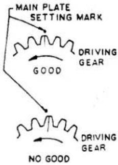 |
- Process Name: Assembly of Sub-Plate Sub-assembly.
| Step | Procedure | Jig and/or Tool Used | Notes | Remarks |
| 1 | Check operation of both lead and following blades. | Pincette | Refer to Fig.19 of page 27. | |
| 2 | Set sub-plate sub-assembly to mounting hole. Assembly Sequence: a. Insert column into sub-plate hole. b. Set hole of shutter speed setting shaft to that of driving shaft. c. Hold the hole portion of shutter speed setting shaft by hand. d. Set hole of following blade release cam to that of lead blade release cam and insert them into the hole of sub-plate sub-assembly in that order while holding them by a pair of pincettes. | Pincette | ||
| 3 | Tighten flat screw (1.4 x 2) made of brass. Tightening torque: 600 g-cm or more. | Pincette Screwdriver | ||
| 4 | Apply cement to the hole of flat screw (1.4 x 1.8) using small brush. | Small brush | Cement should ideally be administered into the hole of flat screw (1.4ø x 1.8). Any cement present outside the chamferred portion must be wiped with a cloth. | |
| 5 | Tighten flat screw(1.4ø x 1.8).Tightening torque:600 g-cm or more. | Pincette-Screw-driver | ||
| 6 | Operation Check:Pinch shutter speed setting shaft by fingers as shown in Fig. (Refer to Fig.20 of page 27 and flip main plate sub-assembly by finger of the other hand. In this case, the sub-assembly should rotate slightly about the shut-ter speed setting shaft. | Refer to Fig.20 of page 27. | Use sacks in fingers to pinch shutter speed setting shaft. | |
| 7 | Insert one end of driv-ing spring into one of gear teeth while rotat-ing ratchet gear clock-wise by a pair of pin-cettes. | Pincette | Refer to Fig.21 of page 27. | |
| 8 | Operation Check:When driving shaft is rotated counterclockwise with a jig or by hand, there shall be no creak-ing or the like. When hand is let off, it should return smoothly by tension of spring, and ratchet pawl should not come off, or spring ends now hooked on should not come off. | Refer to Fig.22 of page 28. |
- Process Name: Clich Spring Assembly
| Step | Procedure | Jig and/or Tool Used | Notes | Remarks | |
| 1 | Set click spring to mounting hole position. | Pincette | Refer to Fig.23 of page 28. | The bent portion of spring should drop into the hole. | |
| 2 | Apply a small amount of cement to the tip-end of flat screw (1.4øx1.4). | Pincette | |||
| 3 | Tighten flat screw (1.4øx1.4). Tightening torque: 600 g-cm or more. | Pincette Screwdriver | |||
| Material | Thickness | Surface Treatment | |||
| #240 | PBS-H | 0.3 | None | ||
| #241 | SK4-M | 0.25 | FB | ||
| #242 | SK4-M | 0.25 | FB | ||
| All these types are identical in configuration. | |||||
- Process Name: Assembly of Body Release Sub-assembly.
| Step | Procedure | Jig and/or Tool Used | Notes | Remarks |
| 1 | Apply G4 grease to body release lever shaft. | Small brush | Small amount suffices. | |
| 2 | Insert body release lever sub-assembly into the shaft. | Pincette | Refer to Fig.24 of page 28. | |
| 3 | Place spring onto the lever. | Pincette | Refer to Fig.25 of page 28. | Longer spring end should be hooked on easily. |
| 4 | Secure flat screw (1.4ø x 2.2) to lever shaft and then tighten it down.Tightening torque:600 g-cm or more. | Pincette Screwdriver | Refer to Fig.26 of page 28. | Do not tighten spring with screw. |
| 5 | Hook shorter end of spring onto the hooking portion of lever. | Pincette | ||
| 6 | Operation Check:Push lever by a pair of pincettes in the direc-tion in which releasing can be made. It is normal when the lever operates smoothly and effortlessly and returns. | Pincette | Refer to Fig.27 of page 28. |
- Process Name: Set Gear Assembly.
| Step | Procedure | Jig and/cr Tool Used | Notes | Remarks | ||
| 1 | Apply G4 grease to'shut-ter blade plate sub-assembly column. | Small brush | Refer to Fig.28 of page 28. | |||
| 2 | Put washer (5.1 x 0.1) into the shaft. | Pincette | ||||
| 3 | Fit set gear B into shut-ter blade plate column. | Pincette | Refer to Fig.29 of page 28. | Gear engaging should be performed with returning cam forced against the dowel of slide lever (driving gear fully turned counterclockwise).Best way to confirm proper engagement, see that tapped hole is in parallel with the third tooth of set gear, as shown. | ||
| 4 | Place washer (3.6 x 2.5) into plate column. | Pincette | ||||
| 5 | Apply G4 grease to slideway on both face of set gear A.In case of #240, be sure to apply grease to inside the chamferred area. | Small brush | Refer to Fig.30 of page 28. | |||
| #240 | #241 | |||||
| No. of Teeth | 30 | 28 | ||||
| Width | 2.2 | 1.6 | ||||
| 0.D. | 12.8 | 12.0 | ||||
| No. of teeth actually provided:#240:19#241:18#242:19 | ||||||
| #240 | #241 | #242 | |
| No. of Teeth | 30 | 28 | 30 |
| Width | 2.2 | 1.6 | 1.6 |
| 0.D. | 12.8 | 12.0 | 12.8 |
| Step | Procedure | Jig and/or Tool Used | Notes | Remarks |
| 6 | Place set gear A into plate column and roller shaft into set gear B. | Pincette | Refer to Fig.31 of page 28. | |
| 7 | Mount set gear pole into plate column with either end first placed in. | Pincette | ||
| 8 | Operation Check:Operate set gear A along the periphery of the groove of set gear B.It should move smoothly and without any creaking. | Refer to Fig.32 of page 28. | Check set gear pole with it being fully forced in. |
- Process Name: Assembly of Slide Lever Charge Spring.
| Step | Procedure | Jig and/or Tool Used | Notes | Remarks |
| 1 | Apply G4 grease to (1) dowel contacting face of charge lever hooked cam, and (2) slideway on dowel of slide lever. | Small brush | Refer to Fig.33 of page 29. | |
| 2 | Hook slide lever charge spring onto spring hook portion, first from the charge lever end and then the other end. | Pincette | Refer to Fig.34 of page 29. | When hooking charge lever, do so with notched side down (main plate side). Hook tip-end of spring onto hooking portion of charge lever as shown in Fig. upward; then, rotate the other end of the spring clockwise by pincettes, while holding portion by hand, so that charge lever can easily be hooked on. |
| 3 | Operation Check: Flip charge lever in such a way that it is pushed upward, and then check spring to see whether or not it comes off or it operates properly. | |||
| Fig. (center) shows the spring properly hooked on in position. |
- Process Name: Assembly of Release Lever.
| Step | Procedure | Jig and/or Tool Used | Notes | Remarks |
| 1 | Apply G4 grease to lever shaft A. | Small brush | Apply grease, making sure that no other part is covered with it. | |
| 2 | Place release lever spring in position. | Pincette | Refer to Fig.35 of page 29. | Longer spring end must come towards assembly man when viewed from the side as shown. |
| 3 | Mount release lever in position, in such a way that longer end comes on top of the slide lever charge spring. | Pincette | Refer to Fig.36 of page 29. | In this case, it will be more convenient and easier if shorter spring end is hooked on to the lever.See portion: for details. |
| 4 | Tighten flat screw (1.4 x 1.8).Tightening torque: 700 g-cm or more. | Pincette Screwdriver | ||
| 5 | Hook longer spring end to the dowel of spring hooking portion. | Pincette | ||
| 6 | Operation Check:Flip slide lever side of lever. If no creaking is heard, it indicates that operation is normal. | Refer to Fig.37 of page 29. | ||
| 7 | Apply rokol paste to hooking portion of lever hooked cam. | Small brush | Do not apply the paste to other part or place. |
- Process Name: Assembly of Driving Shaft (2)
| Step | Procedure | Jig and/or Tool Used | Notes | Remarks |
| 1 | Apply paste to hooked cam. | Small brush | Refer to Fig.38 of page 29. | If release lever is applied with rokol paste in previous process, this procedure may be omitted. |
| 2 | Insert hooked cam into driving shaft in direction shown in Fig.Cam shall drop into driving shaft, avoiding the rise of release lever. | Pincette | Refer to Fig.39 of page 29. | In this case, the dowel of cam driving gear must be engaged in a position shown in Fig.All necessary assembly works, insofar as this process is concerned, should be carried out in that condition. |
| 3 | Apply rokol paste to B-lever hooked cam. | Small brush | Refer to Fig.40 of page 29. | |
| 4 | Insert B-lever hooked cam to driving shaft with solid side on top and protruding side down. | Pincette | Refer to Fig.41 of page 29. | |
| 5 | Put washer 3.1øx0.1 in. | Pincette | ||
| 6 | Apply G4 grease to M-contact control cam. | Refer to Fig.42 of page 29. | Only to area on the cam as shown in Fig. | |
| 7 | Insert M-contact control cam into driving shaft with its solid side on top and cut portion on shutter speed setting shaft. | Pincette | Refer to Fig.43 of page 29. | |
| 8 | Place washer (3.1øx1) into driving shaft. | Pincette | ||
| 9 | Insert slow speed lever into driving shaft with its solid side on top. | Pincette | Refer to Fig.44 of page 30. | |
| 10 | Apply bonding agent to the tip-end of left-hand side flat screw (1.4øx1.7) | Pincette | ||
| 11 | Tighten left-hand side flat screw (1.4øx1.7) Tightening torque: 800 g-cm or more. | Pincette Screwdriver |
- Process Name: Winding of Main Spring.
| Step | Procedure | Jig and/or Tool Used | Notes | Remarks |
| 1 | Wind main spring up to the specified position using winding tool. | Winding tool | Refer to Fig.45 of page 30. | Perform this process with driving shaft detached. |
| 2 | Winding range is shown in Fig.Standard range is when ratchet gear portion is within the line connecting driving shaft and lead blade release lever. | (Visually) | Refer to Fig.46 of page 30. | Because this winding is provisional and fine adjustment must be made in subsequent process, care should be taken not to wind it beyond the range shown in Fig.Do not wind more than one turn in direction of winding. |
- Process Name: Assembly of Device Action Block Sub-assembly.
| Step | Procedure | Jig and/or Tool Used | Notes | Remarks |
| 1 | Lubricate timer segment gear shaft with DOS. | Lubricator | Refer to Fig.47 of page 30. | |
| 2 | Mount timer retainer E on the main plate sub-assembly. | Pincette | Refer to Fig.48 of page 30. | Set retainer to chamferred portion of main plate sub-assembly with its stepped face down. |
| 3 | Operation Check:Check operation of tim-er stop lever in the device action block sub-assembly.Flip tip-end of stop lever lightly by finger. Its operation is normal if there is no creaking nor dragging, and if it should return by ten-tion of spring. | Refer to Fig.49 of page 30. | ||
| 4 | Mount device action block in main plate sub-assembly.Place timer stop lever in such a way that it comes between slide lever charge spring hool position and dowel of slide lever (1 x 1.1).See to it that timer lever comes beneath release lever. | Refer to Fig.50 of page 30. | Carefully note the positions of timer stop lever and timer lever. As shown in Fig. it is convenient to determine positions from both sides of lever. | |
| 5 | Insert screw for setting gear plate and two flat screws into their respective holes. In this case, apply bonding agent to the tip-end of two flat screws. | Pincette | Refer to Fig.51 of page 30. | |
| 6 | Tighten screws at three points.Tightening torque:700 g-cm or more for screw for setting gear plate.600 g-cm or more for flat screws. | Screw-driver |
- Process Name: Assembly of Timer Spring.
| Step | Procedure | Jig and/or Tool Used | Notes | Remarks |
| 1 | Pinch larger ring of timer spring by a pair of pincettes. | Pincette | Refer to Fig.52 of page 30. | |
| 2 | Hook one end (smaller end) of spring onto spring hook dowel of timer segment gear. | Pincette | Refer to Fig.53 of page 30. | |
| 3 | When segment gear side is hooked on, hook the other end thereof to timer spring hook dowel. | Pincette | Refer to Fig.54 of page 31. | |
| 4 | Check if the spring is properly hooked on, making sure that segment gear end is positively seated on the groove of dowel. |
- Process Name: Timer Operation Check.
| Step | Procedure | Jig and/or Tool Used | Notes | Remarks |
| 1 | Set timer to maximum operating angle. | Refer to Fig.55 of page 31. | See to it that timer is positively set in position.No proper setting may be possible if there is any squeaking or the like in timer stop lever and timer level. | |
| 2 | Gear should be hooked onto the timer stop lever more than two-thirds of the height of pitch of gear tooth. | Refer to Fig.56 of page 31. | ||
| 3 | Set driving shaft in position. | Pincette | Refer to Fig.57 of page 31. | See to it that timer does not start the moment driving shaft has been set.This may happen if no clearance exists between timer stop lever and slide 'lever dowel. |
| 4 | Release body release lever.Check if anyabnormal operating sound is heard.See to it that timer operates to maximum operating angle positively. | There should never be any wows and flutters.If a space of a. in previous process is large, it is possible that timer stop lever is brought into contact with gear due to vibrations and the like during operation.Therefore, care should be taken to avoid this. | ||
| 5 | Make sure that timer segment gear forces timer lever is, to allow for timer lever hook portion to escape from the slide lever. | Refer to Fig.58 of page 31. | See if release lever is forced up positively and then comes off the hooked cam, thereby causing driving shaft to rotate. | |
| 6 | See to it that timer continues to operate until segment gear is fully operated to the stopper, even after driving shaft has been released. | It is portable that shock of driving shaft releasing action causes timer stop lever to be hooked onto the gear, thereby stopping timer without it being operated to maximum angle. Thus, care should be taken. |
- Process Name: Assembly of Shutter Speed Setting Shaft.
| Step | Procedure | Jig and/or Tool Used | Notes | Remarks |
| 1 | Apply G4 grease to main plate sub-assembly around shutter speed setting shaft. | Small brush | Refer to Fig.59 of page 31. | |
| 2 | Rotate shutter speed setting shaft by hand and locate outermost position (direction of arrow) to which following blade release lever comes to. | Refer to Fig.60 of page 31. | When the outermost position has been located, do not move shutter speed setting shaft. | |
| 3 | Mount 1.5¢ ball in main plate sub-assembly. | Pincette | ||
| 6 | Place washer (3.1¢ x 0.07) in position. | Pincette | Refer to Fig.61 of page 31. | Make sure that washer does not come into the groove of shutter speed setting shaft. |
| 7 | Apply G4 grease to face of anchor cam and ball slide surface. | Small brush | Refer to Fig.62 of page 31. | Grease to be applied to both shall be very small amount. |
| Apply G4 grease to the entire periphery of gear train change cam. | Small brush | |||
| Apply G4 grease to face of protuded portion of B-cam. | Small brush | |||
| 8 | Insert anchor cam into shutter speed setting shaft with its solid side on top. In this case, note the position of click holes. | Pincette | Refer to Fig.63 of page 31. | 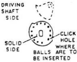 |
| 9 | Insert retainer B (A4-11341) in position. | Pincette | ||
| 10 | Insert gear train change cam into shutter speed setting shaft with its solid side on top. Round side of gear train change cam comes to driving shaft side. | Pincette | Refer to Fig.64 of page 32. | 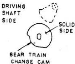 |
| 11 | Insert shutter speed setting shaft retainer C. | Pincette | ||
| 12 | Insert B-cam with its solid side on top, and protruded side opposite to driving shaft. | 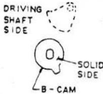 |
- Process Name: Main Plate Assembly.
| Step | Procedure | Jig and/or Tool Used | Notes | Remarks |
| 1 | Mount B-lever spring in position.In this case, shorter end must come on B-lever side and longer side on the plate. | Pincette | Refer to Fig.65 of page 32. | This assembly is provisional and, therefore, any squeaking which may exist is not a trouble, because one end of lever spring is hooked on to the plate in subsequent step. |
| 2 | Mount the plate in position. | Pincette | Be careful of the positions of M-contact lever and B-lever. | |
| 3 | Tighten flat screws (1.4 x 2) at three points.Tightening torque: 600 g-cm or more. | Screwdriver | Remove B-lever spring from the plate. The end now dismounted drops onto the plate pole. | |
| 4 | Remove B-lever spring hooked on the plate. | Pincette | Refer to Fig.66 of page 32. | |
| 5 | Operation Check:There shall be no creaking, squeaking, dragging, etc. on B-lever, M-lever, and M-contact lever,Nor is there falling-off of springs. | Pincette |
- Process Name: Assembly of Control Governor Sub-assembly.
| Step | Procedure | Jig and/or Tool Used | Notes | Remarks |
| 1 | Apply G4 grease to tip-end of control governor, dowel sliding portion of aegment gear, and cam contacting portion of gear train change lever dowel.Gear train change lever dowel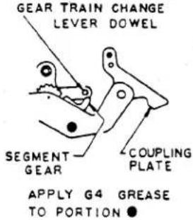 | Small brush | Refer to Fig.67 of page 32. | When setting control governor sub-assembly to hole, push anchor clutch lever in the direction of an arrow so gear train change lever dowel comes into contact with gear train change cam.Position of control governor gear coupling plate. |
| 2 | Set control governor sub-assembly to main plate screw position. | |||
| 3 | Temporarily tighten gear plate setting screw. In this case, loosely tighten screws. Of two screw setting points, one point should be applied with bonding agent. | Pincette Screwdriver | Refer to Fig.68 of page 32. | POSITION OF CONTROL GOVERNOR GEAR COUPLING PLATESLOW SPEED LEVERCOUPLIPLAT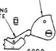 GOOD GOOD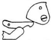 NO GOOD NO GOOD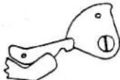 NO GOODWhen tightening, do not apply to much force nor hold it strongly by hand. NO GOODWhen tightening, do not apply to much force nor hold it strongly by hand. |
| 4 | Set gear plate retainer to flat screw hole and insert chamferred portion in between main plate and control governor. | Pincette | Refer to Fig.69 of page 32. | |
| 5 | Tighten flat screw with bonding agent applied to its tip-end.Tightening torque: 600 g-cm or more. | Pincette Screwdriver | ||
| 6 | Tighten gear plate settling screw.Tightening torque: 700 g-cm or more. | Screwdriver | ||
| 7 | Operation Check:Make sure that when driving shaft is set, control governor returns positively.When released, force coupling plate in without causing slow speed lever to come on top of coupling plate or down. | Refer to Fig.70 of page 32. | Contacting con of control governor and slow speed lever shall be such that portion more than two-thirds of control governor is in contact with slow speed lever.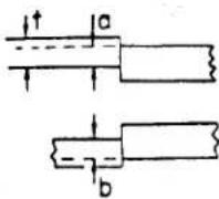 a and b shall be in contact with each other by more than two-thirdsthickness. a and b shall be in contact with each other by more than two-thirdsthickness. |
- Process Name: Assembly of Shutter Speed Setting Shaft (3)
| Step | Procedure | Jig and/or Tool Used | Notes | Remarks |
| 1 | Insert retainer D into shutter speed setting shaft. | Pincette | Refer to Fig.71 of page 33. | M-contact sub-assembly should be placed with retainer in between. |
| 2 | Position solid side of M-contact cam in shutter speed setting shaft in such a way as shown at Fig.71 of page 33. | This dowel should be in contact with M-contact cam. Dowel should never come beneath the cam. | ||
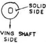 | ||||
| 3 | Insert retainer C into shutter speed setting shaft. | Pincette | ||
| 4(1) | FOR FB-240Insert solid side of shutter speed cam.(Refer to Fig.72 of page 33) Click position shall be 1/2000. | Pincette | Refer to Fig.72 of page 33. | Driving shaft should be assembled with shutter speed cam, with it as being released.Shutter cam is used also for #241. |
| (2) | Insert shutter speed setting gear to shutter speed setting shaft. | Refer to Fig.73 of page 33. | Shutter speed setting gear (A4-11388). | |
| (3) | Tighten flat screw(1.7øx 2.5).Tightening torque:900 g-cm or more. | Screwdriver | ||
| 5 | Operation Check:(1) Check clockwise and counterclockwise rotations of shutter speed setting shaft.There should be no sequeaking, dragging, nor buurs.(2) Check the operation of B-lever, M-contact sub-assembly, gear anchor, gear train change lever, etc. | Refer to Fig.74 of page 33. | No extremely large difference in weight should occur in clicks during shaft rotation.Simply check if it is operating, and no careful checking is not necessary.Arrow in Fig. shows each parts operating direction. | |
| (3) When dial is set to B position, never rotate slow speed lever to bring it in-to contact with gear coupling plate. | Pincette | Refer to Fig.75 of page 33. | When tip-end of slow speed lever is operated in the direction of arrow at point near coupling plate.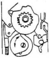 Coupling plate dowel must not move. Coupling plate dowel must not move. | |
| (4) Set shutter speed setting shaft to one second, and now check operation of body only with body release lever released. | Confirm that slow speed lever rotates at about one second. |
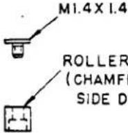 EREDOWN)4 EREDOWN)4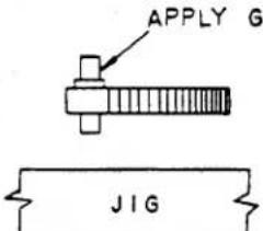 ____FIG 1 ____FIG 1 | 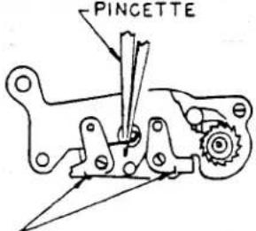 SPRING MUST FIRMLYBE SEATED ON THESEPORTIONS OF THE LEVERFIG 6 SPRING MUST FIRMLYBE SEATED ON THESEPORTIONS OF THE LEVERFIG 6 | 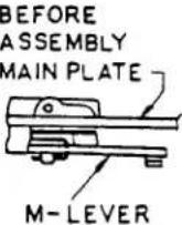 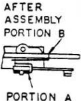 FIG 11 FIG 11 |
M-CONTROL LEVER3LATE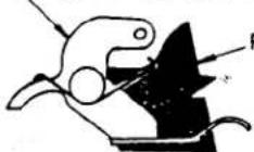 ____FIG 12 ____FIG 12 | ||
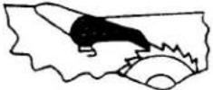 MAKE SURE THAT THE PANEL IS HOOKED FIRMLY AND DOES NOT MOVE BACKWARD FIG 7 MAKE SURE THAT THE PANEL IS HOOKED FIRMLY AND DOES NOT MOVE BACKWARD FIG 7 | ||
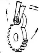 FIG 2 FIG 2 | FLAT SCREW MI.4XI.4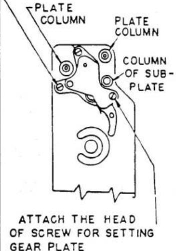 FIG 13 FIG 13 | |
 YFIG 3 YFIG 3 | RA SP 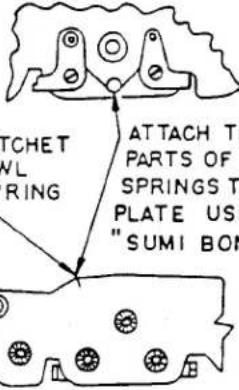 HESE THE O SUB-ING √D" HESE THE O SUB-ING √D" | |
NO GOOD GOOD G4 GREASE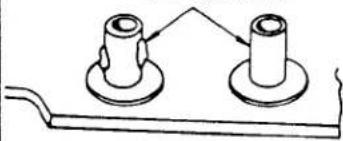 FIG 4 FIG 4 | ||
| FOLLOWING BLADE RELEASE LEVER SPRINGLEAD AND FOLLOWING BLADE RELEASE LEVER CAN BE PUT INTO THE SHAFT MORE EASILY IF SPRINGS ARE PLACED IN SUCH A WAY SHOWN ABOVEFIG 5 | 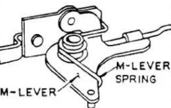 HOOKED PORTION (LARGE) A PORTION BFIG 9 HOOKED PORTION (LARGE) A PORTION BFIG 9 | 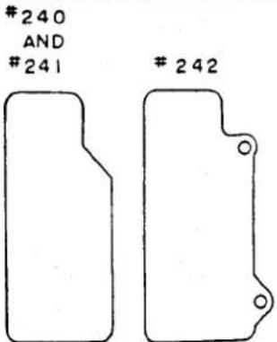 ____MAIN PLATE SUB-ASSEMBLY DIFFERS ONE FROM ANOTHER DEPENDING ON ITS CONFIGURATION, YOU WILL KNOW WHICH TYPE BY CHECKING CONFIGULATIONFIG 14 ____MAIN PLATE SUB-ASSEMBLY DIFFERS ONE FROM ANOTHER DEPENDING ON ITS CONFIGURATION, YOU WILL KNOW WHICH TYPE BY CHECKING CONFIGULATIONFIG 14 |
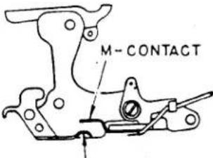 M-CONTROL LEVERFIG 10 M-CONTROL LEVERFIG 10 |
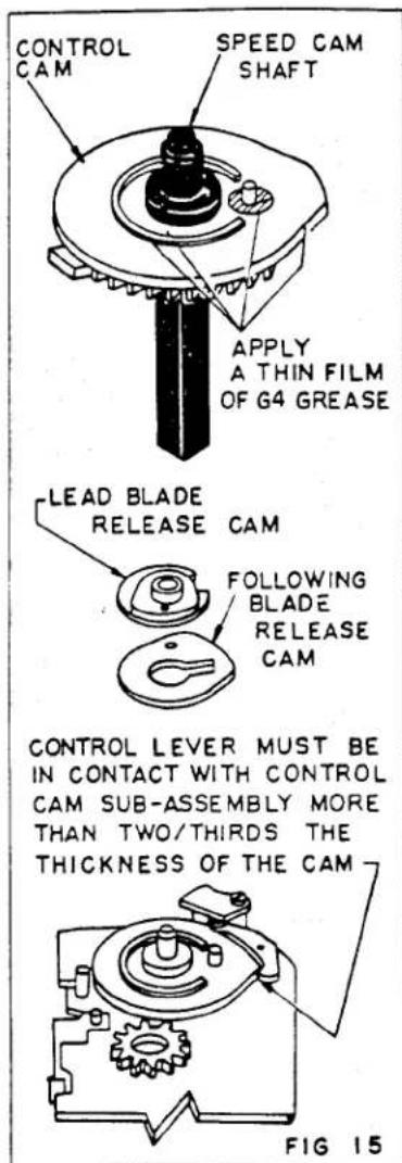
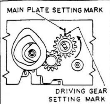
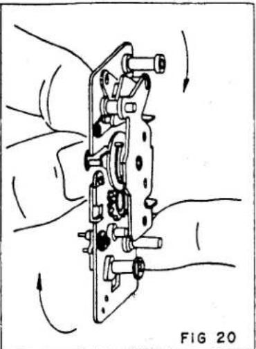
natural_image
Diagram of a mechanical assembly with hands and rotating components, no text or symbols present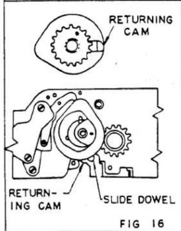
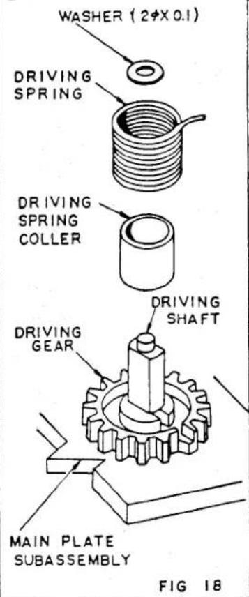
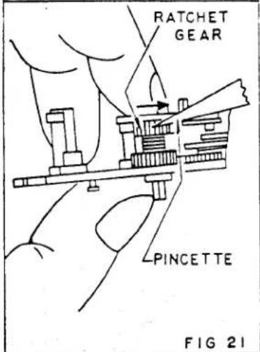
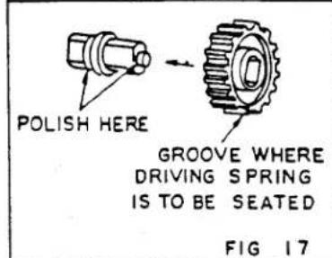
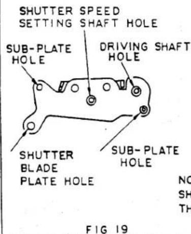
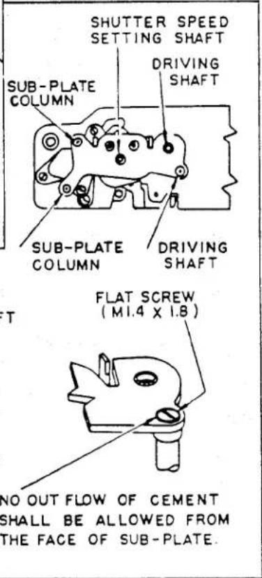
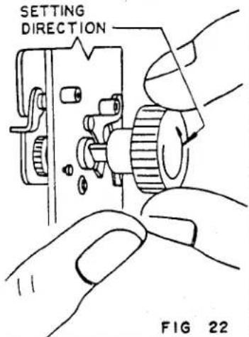 | POF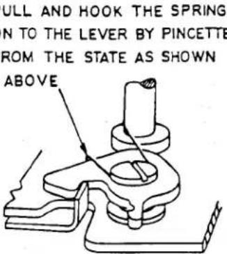 FIG 26 FIG 26 | 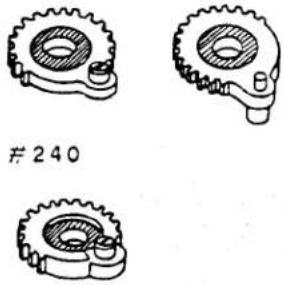 FIG 30 FIG 30 |
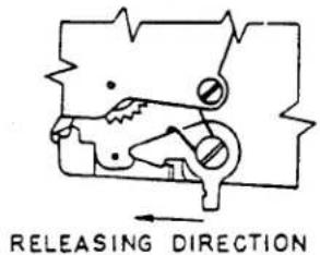 FIG 27 FIG 27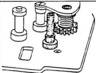 FIG 28 FIG 28 | POLE FORSET SCREW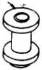 SET GE SET GE 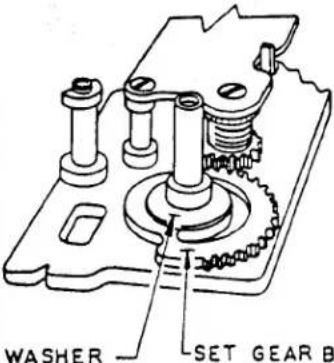 (3.6*X2.5)FIG 31 (3.6*X2.5)FIG 31 | |
| [IMAGE]CLICK SPRINGMOUNTING HOLE[IMAGE]FLAT SCREW( M1.4X1.4 )FIG 23 | 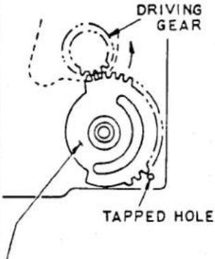 LSET GEAR SHOULD BEENGAGED WITH DRIVINGGEAR IN SUCH A WAY ASSHOWN ABOVE, IN OTHERWORDS, TWO TEETH OFSET GEAR MUST ENGAGEWITH TWO TEETH OFDRIVING GEAR.FIG 29 LSET GEAR SHOULD BEENGAGED WITH DRIVINGGEAR IN SUCH A WAY ASSHOWN ABOVE, IN OTHERWORDS, TWO TEETH OFSET GEAR MUST ENGAGEWITH TWO TEETH OFDRIVING GEAR.FIG 29 | 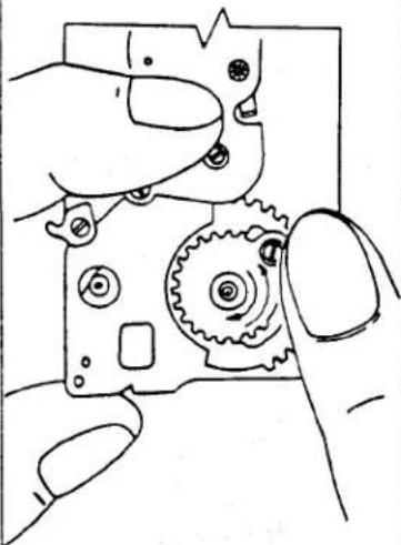 FIG 32 FIG 32 |
| SUB-PLATE COLUMNBODYRELEASELEVER[IMAGE]BODY RELEASELEVER SHAFTSLIDE LEVERFIG 24 | ||
| [IMAGE]FIG 25 | ||
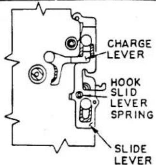 APPLY G4 GREASE TO SHADED AREAFIG 33 APPLY G4 GREASE TO SHADED AREAFIG 33 | DRIVING SHAET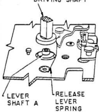 FIG 35 FIG 35 | 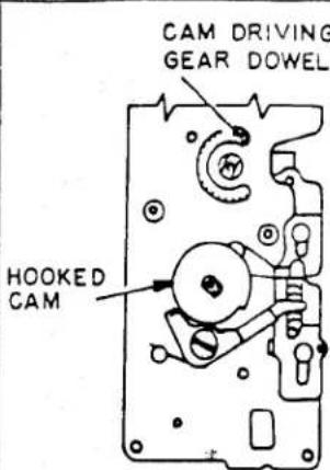 FIG 39 FIG 39 |
| DOWEL SIDE OF SLIDE LEVERCHARGE LEVER ENDPINCETTE | 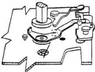 FIG 36 FIG 36 | 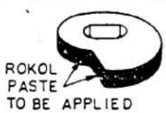 FIG 40 FIG 40 |
| FLIP LEVER IN DIRECTION OF ARROW USING A PAIR OF PINCETTE SO THAT OPERATION CAN NOW BE CHECKED PROPERLY | 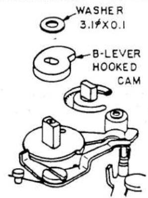 FIG 41 FIG 41 | |
| SPRING MUST COME INTO GROOVE COMPLETELYCHARGE LEVERFIG 34 | FLAT SCREW (M1.4 X1.8)WHERE ROKOL PASTE TO BE APPLIEDFIG 37 |  FIG 42 FIG 42 |
| SIDE WHERE ROKOL PASTE TO BE APPLIEDFIG 38 | TAM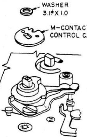 FIG 43 FIG 43 |
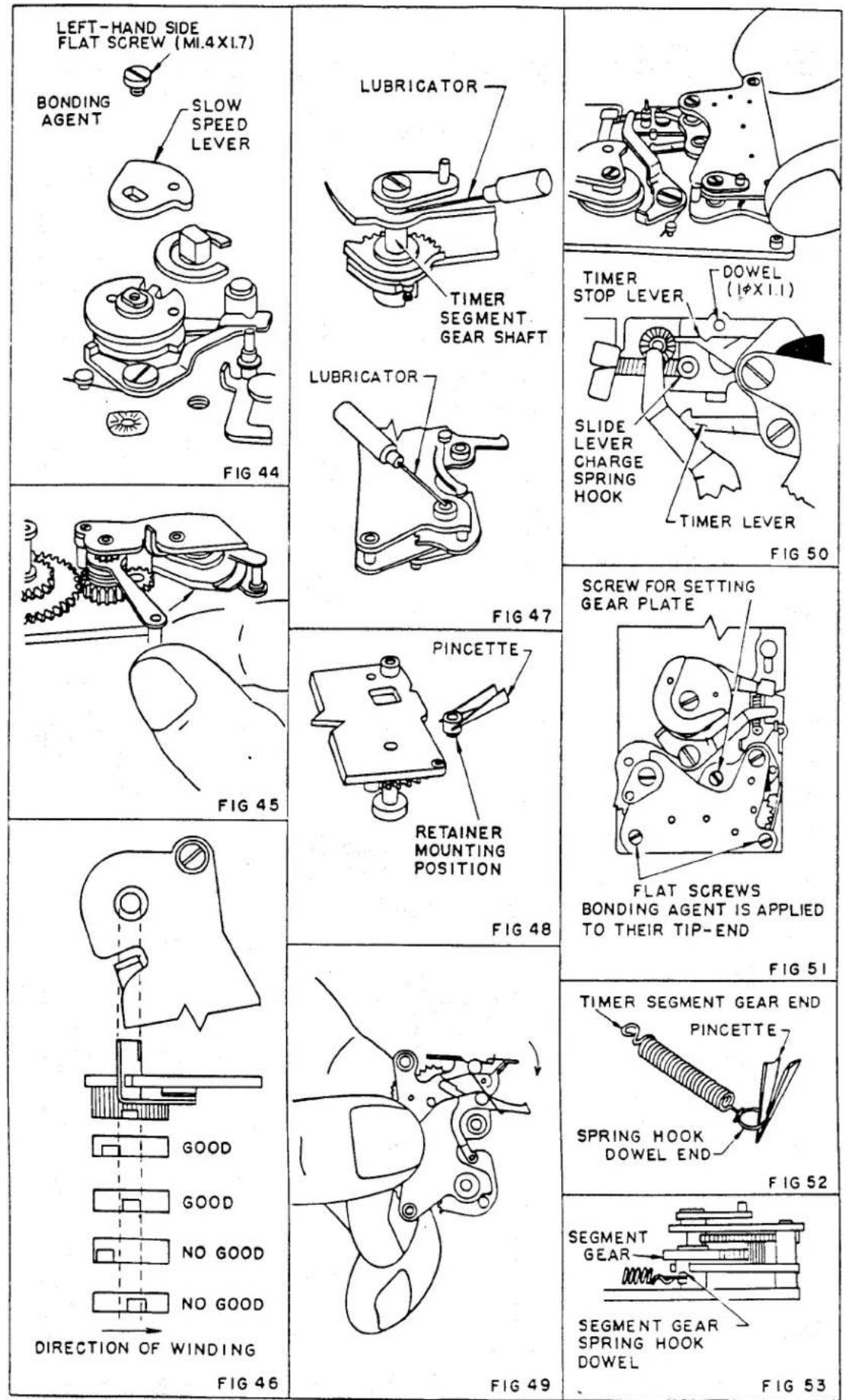
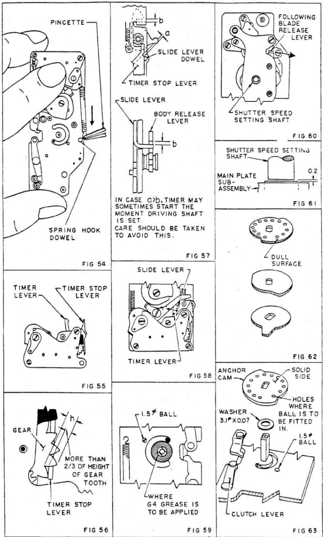
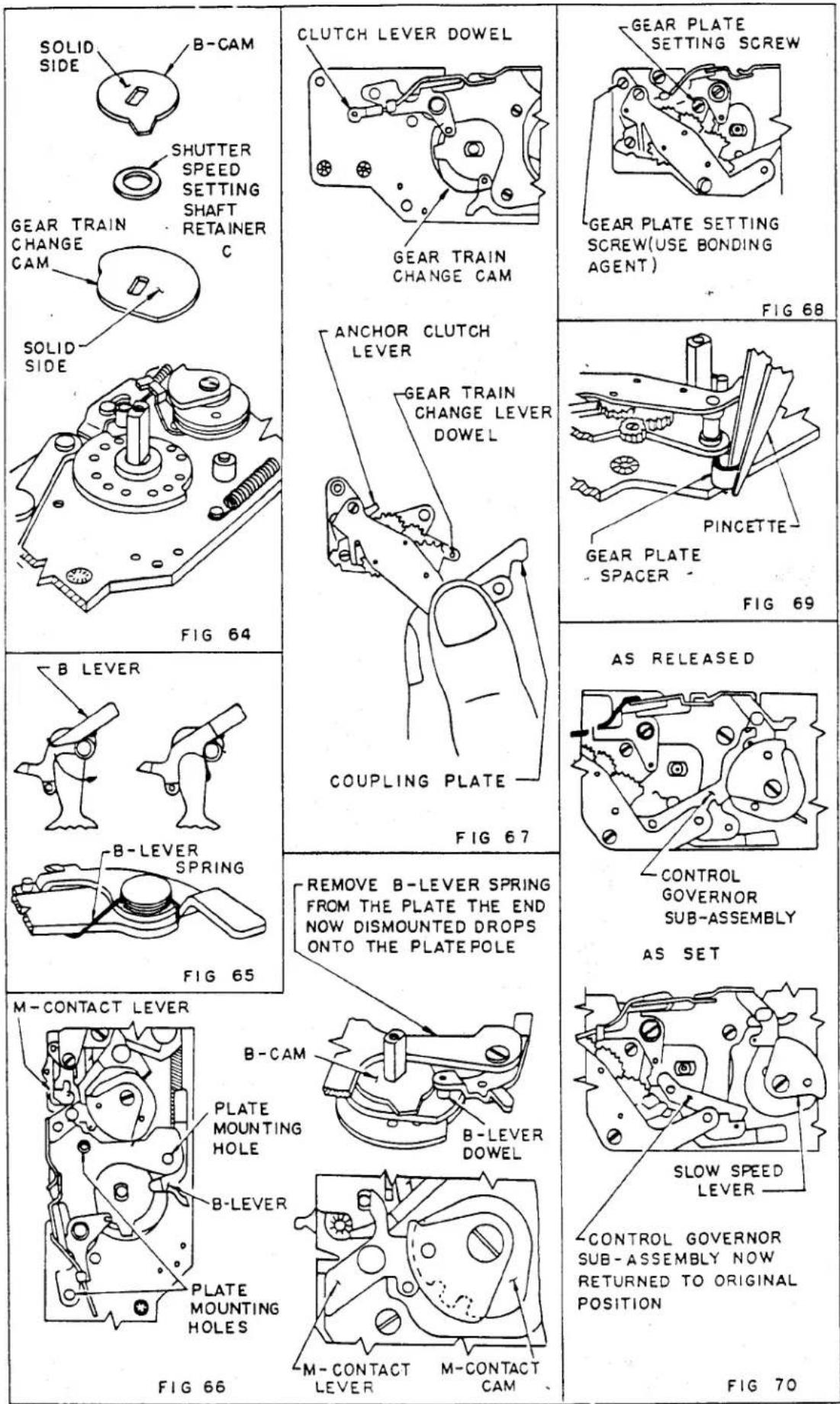
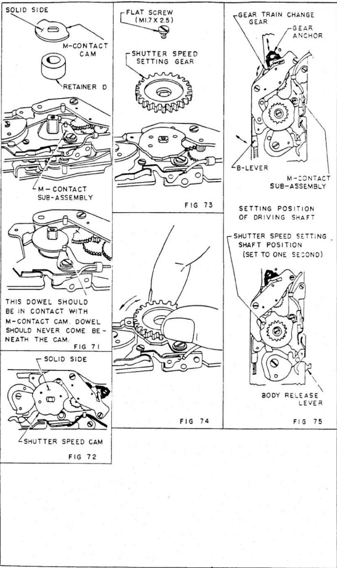
Marke : KONICA MINOLTA
Modell : AutoReflex T2
Kategorie : Nicht kategorisiert