
ZT500 - Wasserfilter ZODIAC - Kostenlose Bedienungsanleitung
Finden Sie kostenlos die Bedienungsanleitung des Geräts ZT500 ZODIAC als PDF.


| Produkttyp | Wasserfilter für Schwimmbecken |
| Modell | ZT500 |
| Marke | Zodiac |
| Filtermedium | Kartuschenfilter |
| Durchflussrate | ca. 8 m³/h |
| Anschlussgröße | 50 mm (2 Zoll) |
| Maximaler Betriebsdruck | 2,5 bar |
| Abmessungen (L x B x H) | ca. 45 x 25 x 30 cm |
| Gewicht | ca. 3,5 kg |
| Stromversorgung | Keine (rein mechanisch) |
| Material | Kunststoff (UV-beständig) |
| Filterfeinheit | 50 Mikrometer |
| Wartung | Kartusche alle 6 Monate wechseln |
| Reinigung | Kartusche mit klarem Wasser abspülen |
| Sicherheit | Druckentlastungsventil integriert |
| Ersatzteile | Filterkartusche ZT500-C (separat erhältlich) |
| Reparierbarkeit | Einfacher Austausch der Kartusche |
| Anwendung | Pools bis 50 m³ |
Häufig gestellte Fragen - ZT500 ZODIAC
Benutzerfragen zu ZT500 ZODIAC
0 Frage zu diesem Gerät. Beantworten Sie die, die Sie kennen, oder stellen Sie Ihre eigene.
Eine neue Frage zu diesem Gerät stellen
Laden Sie die Anleitung für Ihr Wasserfilter kostenlos im PDF-Format! Finden Sie Ihr Handbuch ZT500 - ZODIAC und nehmen Sie Ihr elektronisches Gerät wieder in die Hand. Auf dieser Seite sind alle Dokumente veröffentlicht, die für die Verwendung Ihres Geräts notwendig sind. ZT500 von der Marke ZODIAC.
BEDIENUNGSANLEITUNG ZT500 ZODIAC

ZODIAC
FUNCTIONS OF VALVE POSITIONS
| Valve Position | Function |
| FILTER | Normal Filtration and Vacuuming |
| BACKWASH | Cleaning Filter by reversing the flow |
| RINSE | Used after backwash to flush dirt from valve |
| WASTE | By-passes filter, used for vacuuming to waste or lowering water level |
| RECIRCULATE | By-passes filter for circulating water to pool |
| CLOSED | Shuts off all flow to filter or pool |
FILTER
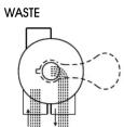
IN FLOW OUT FLOW
WASTE
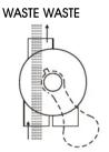
IN FLOW OUT FLOW
CLOSED

IN FLOW OUT FLOW
BACKWASH
WASTE WASTE WASTE

IN FLOW OUT FLOW
RINSE
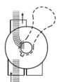
IN FLOW OUT FLOW
RECIRCULATE
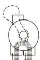
IN FLOW OUT FLOW
GENERAL
SERVICING VALVE( Stop pump, close gate valve in suction&discharge before proceeding):
a. Set handle in filter position. b. Remove cover screws. c. Lift cover and key assembly out.
TO ASSEMBLE:
- Place valve key so that wedge opening is at TOP port (handle in Filter psn.). Flat edge of cover screw lug should align with flat edge of body screw lug.
- Position cover o'ring.
- Secure assembly to body with cover screws. Tighten cover screws evenly and alternately. Do not over-tighten.
WARNING
THIS FILTER OPERATES UNDER HIGH PRESSURE. WHEN ANY PART OF THE CIRCULATING SYSTEM (e.g., CLAMP, PUMP, FILTER, VALVES, ETC.) IS SERVICED, AIR CAN ENTER THE SYSTEM AND BECOME PRESSURIZED. PRESSURIZED AIR CAN CAUSE THE LID OR VALVE TO BE BLOWN OFF WHICH CAN RESULT IN SEVERE INJURY, DEATH, OR PROPERTY DAMAGE
! TURN PUMP OFF BEFORE CHANGING VALVE POSITION.
TO PREVENT DAMAGE TO THE PUMP AND FOR PROPER OPERATION OF THE SYSTEM, CLEAN PUMP STRAINER AND SKIMMER BASKETS REGULARLY.
DO NOT UNSCREW SCREWS OF FLANGE CLAMP WHILE PUMP IS RUNNING.

ZODIAC
TITAN SERIES SAND FILTER
ZT800, ZT900Models:ZT700B,
(Link by Bolt on Valve)

FUNCTION
The filter uses special filter sand to remove dirt particles from pool water. The filter sand is loaded into the filter tank and functions as a permanent dirt removing media. When the control valve is in the FILTER position, the pool water which contains suspended dirt particles, is pumped through your piping system and is automatically directed by the patented filter control valve to the top of the filter tank. As the pool water is pumped through the filter, dirt particles are trapped by the sand bed, and filtered out. The cleaned pool water is returned from the bottom of the filter tank, through the control valve and back to the pool through the piping system. This entire sequence is continuous and automatic. It provides for total recirculation of pool water through your filter and piping system.
After a period of time, the accumulated dirt in the filter causes a resistance to flow, and the flow diminishes. This means it is time to clean your filter. With the control valve in the BACKWASH position, the water flow is automatically reversed through the filter so that it is directed to the bottom of the tank, up through the sand, flushing the previously trapped dirt and debris out the waste line. Once the filter is back-washed of dirt, set control valve to RINSE position and run pump for about 1/2 to 1 minute, and then set the control valve in the FILTER position, to resume normal filtering.
NOTE: Turn pump off before changing valve position.
INSTALLATION
Only simple tools (screwdriver and wrenches), plus pipe sealant for plastic adapters, are required to install and service the filter.
-
The filter should be placed on a level concrete slab, very firm ground, or equivalent. The filter should be placed in the right position so that the piping connections, control valve are convenient and accessible for operation and service.
-
Loading the sand media. Filter sand media is loaded through the top opening of the filter.
a. Loosen the flange clamp and remove filter control valve (if previously installed).
b. Cap internal pipe with plastic cap to prevent sand from entering it.
c. We recommend filling the tank approximately 1/2 way with water to provide a cushion effect when the filter sand is poured in. This helps protect the under-drain laterals from excessive shock.
d. Carefully pour in correct amount and grade of filter sand. (Be sure center pipe remains centered in opening.) Sand surface should be leveled and should come to about the middle of the filter tank. Remove plastic cap from internal pipe.

ZODIAC
- Assemble filter control valve into the filter tank.
a. Insert filter control valve (with o'ring in place) into the tank neck, taking care that the center pipe slips into the hole in the bottom of the valve.
b. Place two plastic clamps around valve flange and tank flange and tighten just enough so that the valve may be rotated on tank for final positioning.
c. Carefully screw pressure gauge (with o'ring in place) into tapped hole in valve body. Do not over-tighten.
d. Connect pump to control valve opening marked PUMP. After connections are made, tighten valve flange clamps with screwdriver, tapping around clamp with screwdriver handle to help seat valve flange clamp.
- Make return to pool pipe connection to control valve opening marked RETURN and complete other necessary plumbing connections, suction lines to pump, waste, etc.
- Make electrical connections to pump per pump instructions.
- To prevent water leakage, make sure all pipe connections are tight.
MAIN DIMENSION
DIMENSION TABLE
| Model | High mm A | Diameter mm B | Valve Port Size mm | Sand kg |
| V700B | 1092 | 723 | 50 | 215 |
| V800 | 1200 | 800 | 50 | 250 |
| V900 | 1300 | 900 | 50 | 350 |

INSTALL/START-UP OF FILTER
- Make sure the correct amount of filter media sand is located in the tank and all connections have been connected and secured.
- Depress control valve handle and rotate to BACKWASH position. (To prevent damage to control valve seal, always depress handle before turning.)
- Prime and start pump according to pump instructions (be sure all suction and return lines are open), allowing the filter tank to fill with water. Once water is flowing out of the waste line, run the pump for at least 1 minute. The initial back-washing of the filter is recommended to remove any impurities or fine sand particles in the sand media.
- Turn pump off and set valve to RINSE position. Start pump and operate until water in sight glass is clear, about 1/2 to 1 minute. Turn pump off and set valve to FILTER position and restart pump. The filter is now operating in the normal filter mode, filtering dirt particles from the pool water.
- Adjust pool suction and return valves to achieve desired flow. Check system and filter for water leaks and tighten connections, bolts, nuts, as required.
- Note the initial pressure gauge reading when the filter is clean. (It will vary from pool to pool depending upon the pump and general piping system.) As the filter removes dirt and impurities from the pool water, the accumulation of dirt in the filter will cause the pressure to rise and diminish the water flow. When the pressure gauge reading is 1.5 bar, higher than the initial "clean" pressure you noted, it is time to backwash the filter (see BACKWASH under filter and control valve functions).
NOTE: During initial clean-up of the pool water it may be necessary to backwash frequently due to the unusually heavy initial dirt load in the water.

ZODIAC
REPLACEMENT PARTS OF FILTER
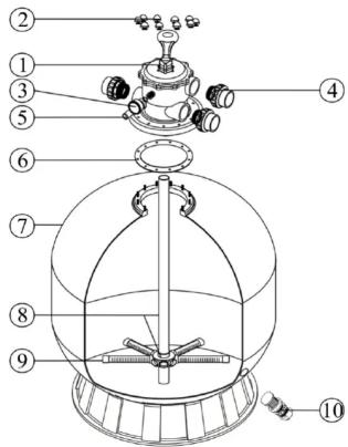
| Item | Part No. | Description | Qty |
| 1 | W88280306 | 50mm Top Mount Valve | 1 |
| 2 | W89010601 | Nut with O-Ring | 1 |
| 3 | W06011009 | Oil Pressure Gauge With O-ring (50 psi) | 1 |
| W01111048 | Connector for Pressure Gauge/Stopper | 1 | |
| 4 | W89280103 | 50mm Union set (3 pieces) with O-Ring | 3 |
| 5 | W89280104 | Sight glass with O-Ring | 1 |
| 6 | W02011126 | Filter Neck Gasket | 1 |
| 7 | W89010612 | ZT700B Filter Tank With Base | 1 |
| W89010603 | ZT800 Filter Tank With Base | 1 | |
| W89010604 | ZT900 Filter Tank With Base | 1 | |
| 8 | W89010611 | ZT700B Lateral Assembly With Center Pipe | 1 |
| W89010607 | ZT800 Lateral Assembly With Center Pipe | 1 | |
| W89010608 | ZT900 Lateral Assembly With Center Pipe | 1 | |
| 9 | W01172010 | ZT800-ZT900 Laterals (185mm) | 8 |
| 10 | W89010107 | Water Drain Set | 1 |
REPLACEMENT PARTS OF MULTIPORT VALVE
| Item Part No. Description Qty | ||||
| 1 W01013003 Handle (Big) 1 | ||||
| 2 W0018008 Pin for Handle | 1 | |||
| 3 W01181027 Washer for Handle | 1 | |||
| 4 W89280301 M6*32 Screw with Nut | 10 | |||
| 5 W01013019 50mm Top Mount Valve Standard Lid (Black) | 1 | |||
| 6 W0014014 Spring for 50mm Top Mount Valve | 1 | |||
| 7 W0011006 O-Ring for 50mm Top Mount Valve Lid | 1 | |||
| 8 W0011022 O-Ring for 50mm Top Mount Valve Rotor | 2 | |||
| 9 W01181002 Washer for Spring | 2 | |||
| 10 | W01021002 50mm Valve Rotor | |||
| 11 | W02311003 Spider Gasket | 1 | ||
| 12 | W01013027 50mm Top Mount Valve Bottom Body (black) | 1 | ||
| 13 | W01013029 50mm Water Tube | 1 | ||
| 14 | W01013030 50mm Diffuser | 1 | ||
| 15 | W02011005 O-Ring for Diffuser | 1 | ||
| 16 | W02011007 O-Ring for Connector | 6 | ||
| 17 | W01013031 50mm Connector with External Thread (Black) | 3 | ||
| 18 | W01171154 50mm Union Adaptor | 3 | ||
| 19 | W01013032 50mm Union Nut (Black) | 3 | ||
| 20 | W89280104 Sight Glass with O-Ring | 1 | ||
| 21 | W01111048 Connector for Pressure Gauge/Stopper | 1 | ||
| 22 | W89021703 Grain Plug with O-ring | 1 | ||
| 23 | W06011009 Oil Pressure Gauge With O-ring (50psi) | 1 | ||



Marke : ZODIAC
Modell : ZT500
Kategorie : Wasserfilter