
RX-950AX MKII - Empfänger ROTEL - Kostenlose Bedienungsanleitung
Finden Sie kostenlos die Bedienungsanleitung des Geräts RX-950AX MKII ROTEL als PDF.


| Produkttyp | AM/FM Stereo Receiver |
| Marke | Rotel |
| Modell | RX-950AX MKII |
| Abmessungen (B x H x T) | 440 x 121 x 340 mm |
| Gewicht (netto) | 9,0 kg |
| Stromversorgung | 120 V / 60 Hz, 220 V / 50 Hz, 240 V / 50 Hz (abhängig vom Bestimmungsort) |
| Leistungsaufnahme | 280 W |
| Ausgangsleistung (8 Ohm, 20-20.000 Hz) | 2 x 50 W RMS, < 0,03 % THD |
| Eingangsempfindlichkeit (Phono) | 2,5 mV / 47 kOhm |
| Eingangsempfindlichkeit (CD, AV/TAPE) | 150 mV / 20 kOhm |
| Klirrfaktor (CD, 20-20.000 Hz) | ≤ 0,03 % |
| Frequenzbereich (CD, AV/TAPE) | 20 - 20.000 Hz (+0 dB, -1 dB) |
| Rauschabstand (CD, AV/TAPE) | 100 dB (IHF, A-bewertet) |
| FM-Empfindlichkeit (75 Ohm) | 10,8 dBf / 0,95 μV |
| AM-Empfindlichkeit | 350 μV/m |
| Lautsprecherimpedanz | Min. 4 Ohm (nur A oder B), Min. 8 Ohm (A+B) |
| Kopfhörerausgang | 8 - 2.000 Ohm |
| Klangregelung | Bass ±6 dB (100 Hz), Höhen ±6 dB (10 kHz) |
| Fernbedienung | Infrarot (RR-927) |
| Besondere Merkmale | Motorisierter Lautstärkeregler, 16 FM/AM-Senderspeicher, A/B-Lautsprecherumschaltung, Bandkopie, AV-Steuerung |
| Reinigung | Mit einem weichen, trockenen Tuch abwischen; keine Lösungsmittel verwenden |
| Zubehör im Lieferumfang | Zimmerantenne (FM), Rahmenantenne (AM), Fernbedienung |
Häufig gestellte Fragen - RX-950AX MKII ROTEL
Benutzerfragen zu RX-950AX MKII ROTEL
0 Frage zu diesem Gerät. Beantworten Sie die, die Sie kennen, oder stellen Sie Ihre eigene.
Eine neue Frage zu diesem Gerät stellen
Laden Sie die Anleitung für Ihr Empfänger kostenlos im PDF-Format! Finden Sie Ihr Handbuch RX-950AX MKII - ROTEL und nehmen Sie Ihr elektronisches Gerät wieder in die Hand. Auf dieser Seite sind alle Dokumente veröffentlicht, die für die Verwendung Ihres Geräts notwendig sind. RX-950AX MKII von der Marke ROTEL.
BEDIENUNGSANLEITUNG RX-950AX MKII ROTEL
ROTEL
RX 950AXMkII
AM/FM Stereo Receiver
Owners Manual
Please write the serial number, date of purchase and the name of your ROTELhi fi AUTHORIZED DEALER in the spaces provided for your future reference.
Serial Number ____.
Purchase date ____.
ROTELhi fi AUTHORIZED DEALER ____.
SAFETY INSTRUCTIONS
WARNING: To reduce the risk of fire or electric shock, do not expose this appliance to rain or moisture.
CAUTION
RISK OF ELECTRIC SHOCK DO NOT OPEN
CAUTION: TO REDUCE THE RISK OF ELECTRIC SHOCK, DO NOT REMOVE COVER (OR BACK). NO USER-SERVICEABLE PARTS INSIDE. REFER SERVICING TO QUALIFIED SERVICE PERSONNEL
- Read Instructions - All the safety and operating instructions should be read before the appliance is operated.
- Retain Instructions - The safety and operating instructions should be retained for future reference.
- Heed Warnings - All warnings on the appliance and in the operating instructions should be adhered to.
- Follow Instructions - All operating and use instructions should be followed.
- Water and Moisture - The appliance should not be used near water - for example, near a bathtub, kitchen sink, laundry tub, in a wet basement or near a swimming pool, etc.
- Carts and Stands - The appliance should be used only with a cart or stand that is recommended by the manufacturer.
PORTABLE CART WARNING
6A. An appliance and cart combination should be moved with care. Quick stops, excessive force and uneven surfaces may cause the appliance and cart combination to overturn. - Wall or Ceiling Mounting - The appliance should be mounted to a wall or ceiling only as recommended by the manufacturer.
- Ventilation - The appliance should be situated so that its location or position does not interfere with its proper ventilation. For example, the appliance should not be situated on a bed, sofa, rug, or similar surface that may block the ventilation openings; or placed in a built-in installation, such as a bookcase or cabinet that may that may impede the flow of air through the ventilation openings.
- Heat - The appliance should be situated away from heat sources such as radiators, heat registers, stoves or other appliances (including amplifiers) that produce heat.
Explanation of Graphical Symbols
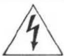
The lightning flash with arrowhead symbol, within an equilateral triangle, is intended to alert the user to the presence of uninsulated 'dangerous voltage' within the product's enclosure that may be of sufficient magnitude to constitute a risk of electric shock to persons.

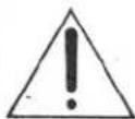
The exclamation point within an equilateral triangle is intended to alert the user to the presence of important operating and maintenance instructions in the literature accompanying the appliance.

- Power Sources - The appliance should be connected to a power supply only of the type described in the operating instructions or as marked on the appliance.
- Grounding or Polarization - The precautions that should be taken so that the grounding or polarization means of an appliance is not defeated.
- Power-Cord Protection - Power supply cords should be routed so that they are not likely to be walked on or pinched by items placed upon or against them, paying particular attention to cords and plugs, convenience receptacles and the point where they exit from the appliance.
- Cleaning - The appliance should be cleaned only as recommended by the manufacturer.
- Nonuse Periods - The power cord of the appliance should be unplugged from the outlet when left unused for a long period of time.
- Object and Liquid Entry - Care should be taken so that objects do not fall and liquids are not spilled into the enclosure through the openings.
- Damage Requiring Service - The appliance should be serviced by qualified factory-authorized service personnel when:
• The power-supply cord or the plug has been damaged; or - Objects have fallen, or liquid has been spilled into the appliance; or
• The appliance has been exposed to rain; or - The appliance does not appear to operate normally or exhibits a marked change in performance; or
• The appliance has been dropped, or the enclosure damaged. - Servicing - The user should not attempt to service the appliance beyond that described in the operating instructions. All other servicing should be referred to qualified factory-authorized service personnel.
Power Lines - An outdoor antenna should be located away from power lines.
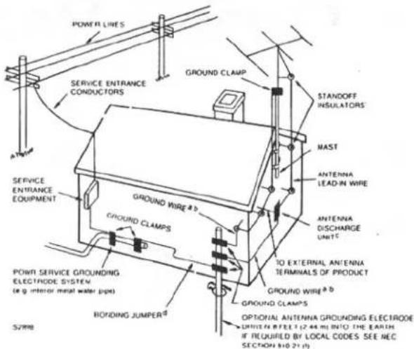
Outdoor Antenna Grounding - If an outside antenna is connected to the receiver, be sure the antenna system is grounded so as to provide some protection against voltage surges and built up static charges. Section 810 of the National Electrical Code, ANSI / NFPA No. 70-1984, provides information with respect to proper grounding of the mast and supporting structure, grounding of the lead-in wire to an antenna discharge unit, size of grounding conductors, location of antenna-discharge unit, connection to grounding electrodes, and requirements for the grounding electrode. See Figure.
a- Use No. 10 AWG (5.3 mm ^2 ) copper, No. 8 AWG (8.4 mm ^2 ) aluminum, No. 17 AWG (1.0 mm ^2 ) copper-clad steel or bronze wire, or larger, as a ground wire.
b- Secure antenna lead-in and ground wires to house with stand-off insulators spaced from 4-6 feet (1.22 - 1.83 m) apart.
c- Mount antenna discharge unit as close as possible to where lead-in enters house.
d- Use jumper wire not smaller than No. 6 AWG (13.3 mm ^2 ) copper, or the equivalent, when a separate antenna-grounding electrode is used.
EXAMPLE OF ANTENNA GROUNDING AS PER NATIONAL ELECTRICAL CODE INSTRUCTIONS
FOR U.S.A. ONLY
A WORD FROM ROTEL
Rotel take this opportunity to thank you for choosing our equipment for your home entertainment. Rotel equipment represents a very high state of the art in sound reproduction, as the result of our everlasting determination to achieve the truly hi-fi performance. Please enjoy the sound Rotel have created for many years to come.
To make sure you get the most out of your equipment, please read this owner's manual carefully before you attempt any connections.
BEFORE CONNECTIONS
1. Place for Installation
Ensure to place the unit in a flat surface where it is free from humidity, vibration, high temperature and not exposed to direct sunlight. Also, be careful not to place the unit in a highly enclosed area without adequate ventilation around the unit. Do not block the ventilation openings at the top and the bottom of the unit to prevent excessive heat built up.
2. Electrical Requirements
Your equipment has been designed to be powered by the local AC voltage. Check the setting of your unit by looking at the rear panel name plate. Never try to plug the unit into an outlet of higher voltage, as this causes a serious fire hazard. Consult your dealer if in doubt.
3. Connecting the Power Cord
Always handle the power cord with care. Ensure to connect the cord to the household wall outlet. When plugging and unplugging make sure the power switch on the unit is turned off.
4. Do not Open the Cabinet
There are no user-serviceable parts inside the cabinet of the unit. Do not attempt to open the cabinet or tamper with the internal components. If water or foreign object falls inside the unit by accident, disconnect the power cord immediately and consult a qualified electrician or your dealer.
5. Cleaning Your Unit
If your unit becomes dirty, wipe it gently with a soft, dry cloth. Never use solvents of any kind.
6. AC Outlet Receptacles
There are two sets of AC outlets for U.S.A. or Canadian version or two sets for U.K. or European versions, on the back panel of the unit, through which power can be supplied to equipments, connected to the unit such as your turntable, CD player or other auxiliary audio components.
Each AC outlet is the switched type, so turning the Power on and off is controlled by the power switch of unit. The total power consumption of the equipments must not exceed the rating of 100 watts maximum.
CONNECTIONS
1. Installing and Connecting Antenna
a) Indoor FM Antenna -The attached indoor antenna wire will suffice for proper, quiet broadcast reception in most good reception areas. To install it, connect the antenna to the FM Antenna terminals (75 ohm) on the back of the unit. Then, stretch the wire out and secure along a wall or where reception is optimal.
- Indoor T-shap Antenna wire (Applicable for U.S.A., Canada or where approved to the usage)
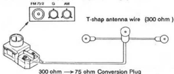
- Indoor Antenna wire (Applicable for European version)
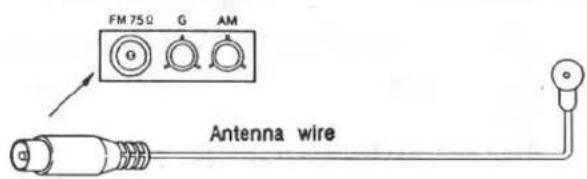
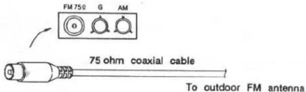
b) Outdoor FM Antenna -In areas of average to weak reception conditions, an outdoor antenna mounted on the roof or top of the building may be necessary for best results. When using such outdoor type antenna, ensure remove the indoor antenna. A 75 -ohm coaxial cable is usually recommended, if using this type cable, properly hook it up to the designated antenna terminals on the back of the unit.
When in doubt on the FM outdoor antenna system, consult your dealer.
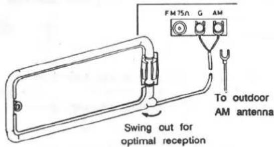
c) AM Antenna -The loop antenna is provided for AM reception. Lock the loop onto the loop holder on the back of the tuner, and connect the two ends to the antenna terminals marked G and AM. Swing out the loop around for finding the best AM reception. In difficult reception
areas, connect an outdoor antenna which is usually a long piece of shielded wire to the AM terminal. Make sure the loop is still connected even if the outdoor or another antenna is used.
2. Connecting components
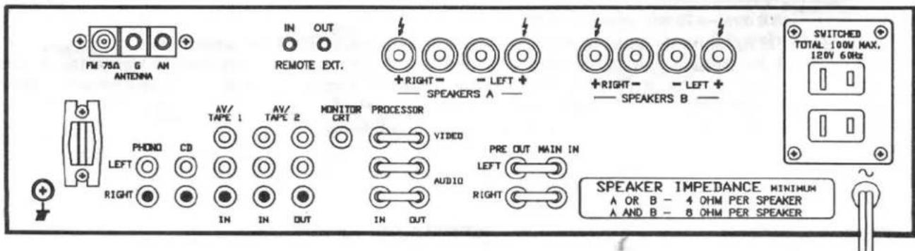
The illustration shows what audio components you can connect to the rear panel of the unit and how they should be properly hooked up via RCA type pin cords, Ensure that the Left and the Right channels are correctly matched between the RCA type sockets of the unit and those on the components.
Connect the grounding wire of the turntable to the GND screw terminal on the back of the unit near the PHONO sockets.
3. Connecting Speakers
a) Use speakers with impedance ratings of 4 to 8 ohms. However, if you wish to hook up 2 sets (pairs) of speaker systems and drive both sets simultaneously, ensure each speaker is rated 8 ohms minimum. Never connect speakers with lower impedance than 8 ohms in this case. The speaker impedance is indicated on the back or in the instruction manual of the speaker.
b) Do not use speakers that have very high capacitive load, say over 0.1 microfarads, as it may cause a damage to the power amplifier section. Normally, most speakers are low capacitance type, but there are a few which do have excessively high capacitance.
c) Use proper speaker cords normally your dealer will recommend, with as low capacitance content as possible. The speaker terminal posts provided on the back of the unit can also take banana plugs.
d) If connecting the speaker cords directly with the bare wire ends, suggest you strip about 1 cm of the insulation shielded cover from the ends of the speaker cords. Twist any exposed strands tightly, and insert the ends properly to the terminal posts.
e) The A speaker terminals are for the speakers in the main sound room. Speakers connected to A may be rated as 4 to 8 ohm impedance, unless A + B speaker operation is expected. If A + B speaker operation is intended, both pairs of speakers should be 8 ohm rated on their back panel or in their respective owners manual. For private headphone listening, the speakers may be turned off by setting the front panel speaker selector switch to the OFF position.
f) The B speaker terminals are for speakers located in another room. To listen to the B speakers only, set the front panel speaker selector switch to the B position.
g) Ensure the Left and the Right channels are correctly connected between the unit and the speakers, and make sure for each channel the "+" and the "-" are also correctly matched. Check that the speaker cord ends (exposed tips) on the terminal posts are not stray and touching one another, which will cause short circuits and may damage both the unit and the speakers.
SINGAL PROCESSOR TERMINALS
There are two sets of terminals for AUDIO/VIDEO inputs, which allows to use with audio equalizer, surround sound decoder and video enhancer etc., simply remove jumper pins and hook up the connecting cords as per the instructions supplied with that components.
Note: When these terminals are not in use, please make sure the jumper pins are plugged in properly.
PRE OUT/ MAIN IN TERMINALS
These terminals are intended for use with any optional equipments designated to be installed between the preamplifier and the main amplifier or for separate use of either section alone such as audio equalizer or reverberation unit can be used, or another preamplifier or main amplifier may be hooked up. Simply discount the jumper pins and follow the instruction supplied with the accessory equipments.
Note: When these terminals are not in use, please make sure the jumper pins are plugged in properly.
REMOTE EXTENSION CONNECTOR
The remote extension IN and OUT connections are for use in custom installation. Those will be useful for Remote Repeaters and Remote Infrared Receiver connections, It's designed to work with Video Link products from Xantech Corporation. These allow to remote control RCC-945 or RD-960BX or RT-940AX, or RA-985BX when use RR-927 remote control handset.
SWITCHES AND CONTROLS
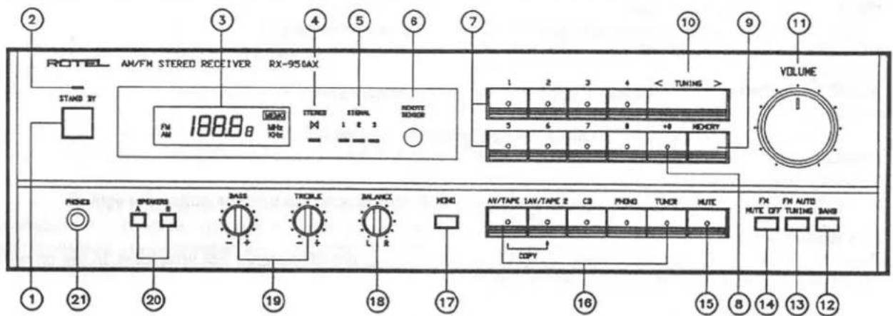
(1) Stand-by Button (Power)
Press this button to turn on and off the unit, also can be activated by remote control.
(2) Power Indicator
The LED indicator glows, while the power cord is connected to a live AC outlet, regardless of the stand-by button on / off.
(3) Frequency Display and Multi-function Indicator
1) The frequency of the station selected is displayed. The band chosen, FM or AM, is also shown together with MHz for FM or kHz for AM on the frequency display.
2) The word MEMORY lights up while the Memory button is activated.
(4) Stereo Indicator
The LED indicator glows when stereo broadcasting station is tuned in and when the Mono button is deactivated for the stereo operation. It will also not light up for very weak stereo signals which the tuner will not receive in stereo.
(5) Signal Indicator
The 3-LED indicator lights up to show the incoming signal strength (sensitivity). Receiving condition for a broadcast is optimized when all 3 LED's or as many LED's illuminated.
(6) Remote Sensor
Receives the operating commands in the form of infrared beams emitted from the remote transmitter unit.
(7) Stations Button
Pressing one of these buttons will tune the tuner to the frequency stored in the memory. Pressing the Memory button followed by one of these buttons will store up to 16 AM or FM stations randomly in the memory. The LED on each station button will light up when station button pressed.
Caution: If the AC power is removed from the tuner for more than two weeks, the frequencies stored in the memories will be lost.
Note: Each time you switch the tuner on, it will tune to the station frequency to which it was previously tuned.
(8) +8 Button
The tuner can store up to 16 different frequencies in its memory. The first 8 are selected (or stored) just by pressing the appropriate button. The second 8, numbers 9 to 16, are selected by pressing the +8 button and follow to press the desired station button.
The LED on it will light up when the +8 button pressed.
(9) Memory Button
Stores frequencies in the tuner's memory. To store a frequency first tune to the desired broadcast program using the Tuning button. Then press the Memory button followed by one of the station buttons marked 1 to 8 and 9 to 16 with +8 button. Although there are only 8 buttons marked for positions 1 to 8, the +8 button converts the buttons to positions 9 to 16. So the buttons have double functions, e.g., the button 1 is also 9 when used with the +8 button.
The Memory LED will light up during this process. Note that once the Memory button is pressed, you must press the required station button within a few seconds to store the station frequency. If the Memory indicator is no longer light, you must press the Memory button again efore storing the required frequency.
For example, to store desired local station in the station button 12, first tune in to the station, press the Memory button, then press the +8 button and follow to press the station button 4.
(10) Tuning Button
Allows to tune in frequencies. Press the right side marked > to tune in the higher frequencies and the left side marked < to tune in the lower frequencies.
(11) Volume Control
Used to regulate the volume level. Turn clockwise to increase the volume level and counterclockwise to reduce it. Due to the high quality material and construction used on the volume control for sound quality, the sound level will not rise sharply at low settings. Normally, the control is recommended to be set between 11:30 to 2:00 o'clock position with other Rotel's equipments connected, but a finite adjustment will depend on the sensitivity of your speakers.
The volume control has a built-in motor drive, which allows to operate by remote transmitter handunit. The LED indicator on the knob shows the position of the level set.
(12) Band Selection Button
Allows to select reception on FM or AM band.
(13) FM Auto Tuning Button
Permits to choose auto or manual tuning. In the auto mode, pressing either end of the Tuning button will cause the tuner to increase or decrease, depending on which end of the Tuning button pressed, the received frequency until a reasonably strong signal is received. At this point the tuning will stop automatically.
In the manual mode, pressing either end of Tuning button causes the tuner to increase or decrease the received frequency only for as long as the Button is depressed.
Note: Auto tuning does not operate for AM band.
(14) FM Muting Off Button
For normal use, the button is deactivated to suppress the interstation noise during FM tuning. Depress the button when tuning for a very weak FM broadcast in the manual tuning mode.
(15) Audio Muting Button
Pressing the button will immediately cause a large reduction in volume level of sound, and pressing it again to restore the previous one.
This button is most useful when you wish a temporary period of quieter sound. When audio muting is in operation, the LED indicator on it lights up.
(16) Function Selector Button
Allows to choose any input source connected to the unit you wish to listen to.
AV/TAPE 1 - To play Cassette Tape Deck, Video Cassette Recorder, or Video Dise Player connected to AV/TAPE 1.
AV/TAPE 2 - To play Video Cassette Recorder, Video Disc Player and or other auxiliary components connected to AV/TAPE 2.
CD - When playing the connected Compact Disc Player.
PHONO - When playing the connected Turntable.
TUNER - When listening to FM or AM broadcasts.
When the desired source program is in operation, the LED indicator on the function button will light up.
(17) Mono Button
Pressing the button converts any input signal to be monophonic, included stereo FM broadcast. In the off position, the stereo sources are produced stereophonically.
(18) Balance Control
Set normally at the center position for equal volume level from both speakers. Turning to the right decreases the sound from the left speakers, and turning to the left decreases the sound from the right speakers. Use the control only when there is an unbalance in the sound level between the two speakers.
(19) Tone Controls
The BASS control regulates the low frequencies and the TREBLE control regulates the high frequencies. The center points are for the flat frequency response. Turn clockwise to boost the response and counterclockwise to reduce it, if your listening room acoustics are excessively lively or dead and requires the compensations when adjusts by reallocate the furnitures, or the speakers etc., are all failed.
(20) Speaker Button
The SPEAKER switch, on the front panel of the RX-950AXMKII, will allow you to control two pairs of speakers. We have labeled the speaker switch with OFF, A, B and A+B speaker settings. If you wish to privately listen to headphones with this receive, turn the SPEAKER switch to the OFF position. If you want to operate A or B speakers only, set the speaker switch to the appropriate position. The speaker A+B setting will play both pairs of speakers at the same time, Please note that both pairs of speakers should be rated as 8 ohm minimum impedance for use as A+B speaker mode.
(21) Headphones Jack
For private listening, plug your headphones to this Jack. turn the SPEAKER switch to the OFF position.
Remote Control Function
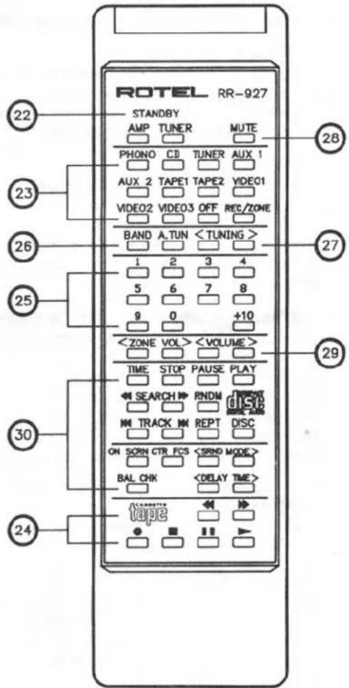
(22) Standby Button for on/off.
(23) Function Selector Buttons (same as item 16).
(24) Cassette Control Buttons- Permit you to remote control Rotel's RD-960BX cassette deck connected to the REMOTE socket on the rear panel.
Press << button to rewind tape.
Press > button to play back tape.
Press >> button to advance tape rapidly forward.
Press II button for temporary suspension of tape motion during recording or playback. Pressing the button a second time will restart the tape, returning the tape deck section to mode before interruption.
Use ● button when you wish to record.
Press ■ button to disengage any control mode, be it playback, record, fast forward, or rewind.
(25) Preset Station Buttons (same as item 7, 8).
(26) Band Selector Button (same as item 12).
(27) Tuning Buttons (same as item 10).
(28) Audio Muting Button (same as item 15).
(29) Volume Button (same as item 11).
(30) Compact Disc Player control buttons Permit you to remote control Rotel's RCD-970BX or RCD-975 compact disc player.
WORDS ON OPERATIONS
Precautions
-
Before commencing operation, check to see if all connections are properly made.
-
Always ensure to set the Volume control to the minimum position before turning on the Power switch.
Playing Turntable
- Set to the PHONO position on the Function selector button.
- Use only a high quality cartridge to obtain the maximum potential from the unit's high quality phono circuit. Usually using cartridges as recommended by your dealers will prevent any grief on the suitable matching.
- Start playing the turntable, then raise the volume to the desired listening level.
Operating CD Player
- Set to the CD position on the Function selector button.
- Read the instruction manual of your player carefully to maximize the full potential. Using higher quality interconnecting cords between your CD player and the amplifier may often improve sound quality.
- Start playing CD, then raise the volume to the desired listening level.
Tuner Reception
- Set to the TUNER position on the Function selector button, and select AM or FM by BAND button.
- Tune in to the desired station by tuning button or preset tuning buttons.
- Raise the volume to the desired listening level.
Memory Backup
As explained above, the memory for the preset stations is retained as long as the power cord is plugged into an AC outlet, regardless of the position of the Power button. However, if you leave the power cord unplugged for over two weeks, or if there is a power failure for over two weeks, the stored frequencies will be lost.
In such case, the operation for storing frequencies in the memory have to be done again from the beginning.
Tuning Modes
Bear in mind that there are 3 modes of tuning with the tuner: auto uning, manual tuning, and preset (memory) tuning. The simplest is the pereset tuning, as you only have to stored up to 16 of your favorite FM or AM stations once and recall any one of them with one touch (or two touches in case of the buttons 9 to 16). Make sure to learn the proper method for the storage in the memory as instructed above.
Tape Deck Playback
- Set to the AV/TAPE 1 or AV/TAPE 2 on Function selector button while your tape deck is connected to the AV/TAPE 1 or AV/TAPE 2 inputs on the back of the unit.
- Use only a good quality cassette tape deck (in terms of sound quality) or a DAT deck, etc. for maximizing the full potential of the amplifier.
- Starting the playback, and then raise the volume to the desired level.
Recording Tape Deck
- If your tape deck is connected to the AV/TAPE 2 outputs on the back of the unit, you can record any inputs on the Function selector and proceed the recording with your tape deck.
- During recording operation, the volume control and the Tone controls have no effect on the recorded signal being fed to the AV/TAPE 2 outputs.
Tape Copying
Two Tape decks are used to perform Tape-to-Tape copying. The unit allows copying from AV/TAPE 1 to AV/TAPE 2 only.
- Set AV/TAPE 1 button in depressed position.
- Set AV/TAPE 1 deck in playback mode and AV/TAPE 2 deck in recording mode, then copying start.
- During the copying, you may listen to the singal with the volume control, etc., set as desired since they will not affect the recording signal.
Playback and Recording with AV Equipments
The RX-950AX provides the connection and switching of audio-video components, so that this unit can be used as an AV control center. There are one set of inputs for a stereo AV component such as a video disc player and one set of inputs/outputs for a stereo video inputs. There is also a separate monitor CRT output for connection of a color monitor TV for high quality viewing. This system then not only provides for easy selection of video sources, but also allows high performance operation for excellent sound quality such as digital sound from Hi-Fi video recorder. In addition, sound track of video components can be dubbed onto a tape recorder connected to the receiver, or vice versa. Video dubbing is also possible from AV/ TAPE 1 to AV/ TAPE 2.
To carry out playback with the equipment connected to the AV/ TAPE inputs, set the function selector to AV/ TAPE 1 or AV/ TAPE 2.
Set the TV or video monitor to the video input mode to view the picture. Adjust the volume and other controls on the receiver to suit your needs.
Recording (Dubbing)
Set the function selector to AV/ TAPE 1, where the source to be recorded is connected. Then record with the video recorder connected to the AV/ TAPE 2 terminals on the rear panel. The video signal being recorded can be monitored by the connected TV or video monitor. For advanced applications, such as combining sound from an audio source with a video signal and recording both on the video cassette recorder connected to the AV/ TAPE 2 terminals.
HUM AND NOISE
In any high fidelity installations, hum may be caused by the interconnection of turntable, tuner, amplifier and speakers as the result of wiring, different grounding or locations of components. f hum is experienced with your unit, disconnect everything but the speakers from the unit. Plug in the truntable and if hum or howing appears, move it away from the speakers as much as possible.
Note hum may also be induced by defective cable connections or by running the cables too close to strong AC field.
When your unit picks up noise during the reception of broadcasts, causes are mostly due to external objects such as fluorescent lamps and house appliances using motor or thermostat, or others than may induce noise. Either relocating the unit away from the noise sources or using an improved outdoor antenna may readily resolve the problem. In the event you cannot find the cause, consult your dealer or qualified electrician.
SPECIFICATIONS RX-950AX
| AMPLIFIER SECTION | |
| Continuous Power Output. | 50 watts* per channel, min. RMS both channels driven into 8 ohms from 20 to 20,000 Hz with no more than 0.03 % total harmonic distortion. |
| DIN Power Output | 85 watts per channel (1 kHz, 4 ohms, 1 % THD) |
| Total Harmonic Distortion(20 to 20kHz from CD) | No more than 0.03 % (contin uous rated power output) |
| Intermodulation Distortion(60 Hz: 7 kHz= 4:1) | No more than 0.03 % (contin- uous rated power output) |
| Output: Speaker | 4 ohms minimum |
| Headphone | 8 - 2,000 ohms |
| Damping Factor | 100 (20 to 20,000 Hz, 8 ohms) |
| Input Sensitivity/ Impedance: | |
| PHONO | 2.5 mV/ 47 kohms |
| CD, AV/TAPE 1,2 | 150 mV/ 20 kohms |
| Overload Level (THD 0.5% 1 kHz): | |
| PHONO | 200 mV |
| CD, AV/TAPE 1,2 | 5 V |
| Frequency Response: | |
| PHONO | 20 to 20,000 Hz +/-0.3 dB (RIAA STD) |
| CD, AV/TAPE 1,2 | 20 to 20,000 Hz +0 dB, - 1 dB |
| Tone Control: | |
| BASS | +/- 6.0 dB (100 Hz) |
| TREBLE | +/- 6.0 dB (10 kHz) |
| Signal-to-Noise Ratio (IHF, A network): | |
| PHONO | 82 dB |
| CD, AV/TAPE 1,2 | 100 dB |
| FM TUNER SECTION | |
| Usable Sensitivity | 10.8 dBf/ 0.95 uV (75 ohms) |
| 50 dB Quieting Sensitivity: | |
| Mono | 14.8 dBf/ 1.5 uV (75 ohms) |
| Stereo | 37.2 dBf/ 20 uV (75 ohms) |
| Signal-to-Noise Ration (at 65 dBf): | |
| Mono | 80 dB |
| Stereo | 75 dB |
| Harmonic Distortion (at 65 dBf): | |
| 1 kHz | 0.07% (mono), 0.25% (stereo) |
| Frequency Response | 30 to 15,000 Hz +/- 1.0 dB |
| Capture Ratio | 1.0 dB |
| Alternate Channel Selectivity:(+/-400 kHz) | 63 dB |
| Spurious Response Ratio | 95 dB |
| Image Response Ratio | 45 dB |
| IF Response Ratio | 95 dB |
| AM Suppression Ratio | 58 dB |
Stereo Separation:
100 Hz/1 kHz/10 kHz
Subcarrier Product Ratio
Antenna Input
43 dB/ 46 dB/ 38 dB
60 dB
75 ohms unbalanced
AM TUNER SECTION
| Sensitivity | 350 uV/ m |
| Selectivity | 35 dB |
| Signal-to-Noise Ratio | 55 dB |
| Image Response Ratio | 40 dB |
| IF Response Ratio | 60 dB |
| Antenna | Loop Antenna |
MISCELLANEOUS
| Power Requirement. | 120 V/ 60 Hz, 220 V/ 50 Hz, 240 V/ 50 Hz (dependinh on destinations) |
| Power Consumption | 280 watts |
| Dimension (overall) | 440 (W) x 121 (H) x 340 (D)mm |
| 17-3/8" x 4-13/16" x 13-3/8" | |
| Weight (net) | 9.0 kg/ 19.8 lbs |
- Specifications and design subject to possible modification without notice.
- *Measured pursuant to the Federal Trade Commission's Trade Regulation Rule or, Power Claims for Amplifiers (applicable to the U.S.A. only).

- ROTEL
- RX 950AXMkII
- AM/FM Stereo Receiver
- Owners Manual
- SAFETY INSTRUCTIONS
- Explanation of Graphical Symbols
- A WORD FROM ROTEL
- BEFORE CONNECTIONS
- Place for Installation
- Electrical Requirements
- Connecting the Power Cord
- Do not Open the Cabinet
- Cleaning Your Unit
- AC Outlet Receptacles
- CONNECTIONS
- Installing and Connecting Antenna
- Connecting components
- Connecting Speakers
- SINGAL PROCESSOR TERMINALS
- PRE OUT/ MAIN IN TERMINALS
- REMOTE EXTENSION CONNECTOR
- SWITCHES AND CONTROLS
- Stand-by Button (Power)
- Power Indicator
- Frequency Display and Multi-function Indicator
- Stereo Indicator
- Signal Indicator
- Remote Sensor
- Stations Button
- +8 Button
- Memory Button
- Tuning Button
- Volume Control
- Band Selection Button
- FM Auto Tuning Button
- FM Muting Off Button
- Audio Muting Button
- Function Selector Button
- Mono Button
- Balance Control
- Tone Controls
- Speaker Button
- Headphones Jack
- Remote Control Function
- WORDS ON OPERATIONS
- Precautions
- Playing Turntable
- Operating CD Player
- Tuner Reception
- Memory Backup
- Tuning Modes
- Tape Deck Playback
- Recording Tape Deck
- Tape Copying
- Playback and Recording with AV Equipments
- Recording (Dubbing)
- HUM AND NOISE
Marke : ROTEL
Modell : RX-950AX MKII
Kategorie : Empfänger