
Iso Leg Extension Sterling - Fitnessgeräte TAURUS - Kostenlose Bedienungsanleitung
Finden Sie kostenlos die Bedienungsanleitung des Geräts Iso Leg Extension Sterling TAURUS als PDF.


| Produkttyp | Beinstrecker (Leg Extension) |
| Marke | TAURUS |
| Modell | Iso Leg Extension Sterling |
| Modellnummer | TF-SL7025 |
| Klasse | S (kommerziell) |
| Maximales Benutzergewicht | 150 kg (330 lbs) |
| Maximale Gesamtbelastung | 300 kg (2 x 150 kg) |
| Produktabmessungen (L x B) | 1300 x 1697 mm |
| Produktgewicht | 130,9 kg (289 lbs) |
| Stromversorgung | Keine (manuell) |
| Verwendungszweck | Krafttraining für die Beine |
| Einstellmöglichkeiten | Verstellbarer Sitzpolster und Griffe |
| Gewichtsscheibenkompatibilität | Olympia-Gewichtsscheiben (50 mm Loch, max. 500 mm Ø) |
| Maximale Gewichtsscheiben pro Seite | 150 kg |
| Montage | Erforderlich, professionelle Installation empfohlen |
| Werkzeuge | Ratsche, Schraubenschlüssel, Gummihammer, Inbusschlüssel, Kreuzschlitzschraubendreher |
| Wartung | Regelmäßige Inspektion und Schmierung nach Zeitplan |
| Reinigung | Mit feuchtem Tuch und milder Seife |
| Sicherheitshinweise | Vor Gebrauch lesen, Kinder fernhalten, auf ebener Fläche verwenden |
| Ersatzteile | Verfügbar, nur Originalteile verwenden |
| Garantie | Erlischt bei Verwendung von Nicht-Originalteilen |
| Zertifizierung | Geprüft nach Klasse S |
Häufig gestellte Fragen - Iso Leg Extension Sterling TAURUS
Benutzerfragen zu Iso Leg Extension Sterling TAURUS
0 Frage zu diesem Gerät. Beantworten Sie die, die Sie kennen, oder stellen Sie Ihre eigene.
Eine neue Frage zu diesem Gerät stellen
Laden Sie die Anleitung für Ihr Fitnessgeräte kostenlos im PDF-Format! Finden Sie Ihr Handbuch Iso Leg Extension Sterling - TAURUS und nehmen Sie Ihr elektronisches Gerät wieder in die Hand. Auf dieser Seite sind alle Dokumente veröffentlicht, die für die Verwendung Ihres Geräts notwendig sind. Iso Leg Extension Sterling von der Marke TAURUS.
BEDIENUNGSANLEITUNG Iso Leg Extension Sterling TAURUS
TAURUS®
Owner's Manual
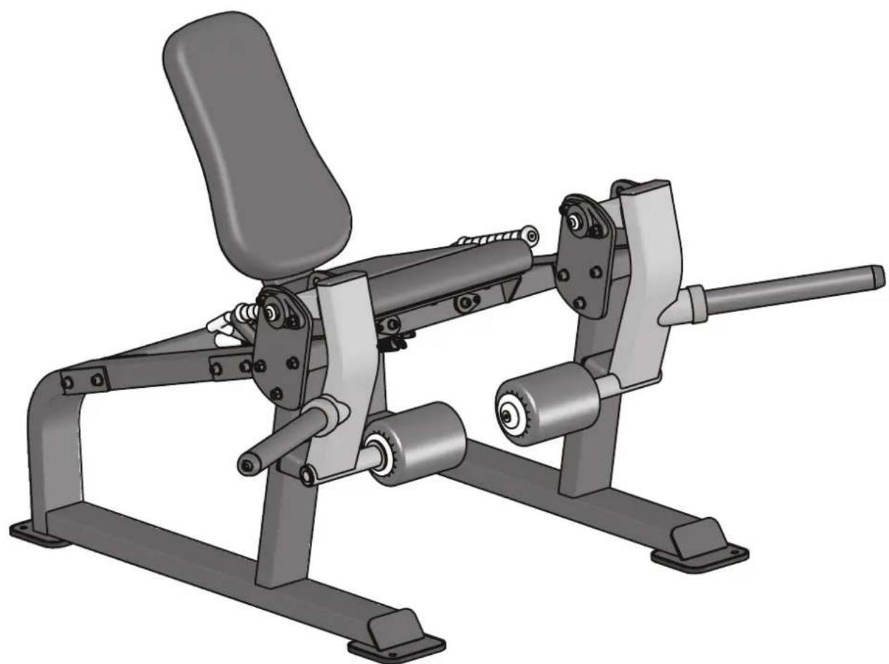
natural_image
3D rendered image of a fitness exercise machine with adjustable arms and legs (no text or symbols visible)TF-SL7025
ISO LEG EXTENSION STERLING
! CAUTION
Read all precautions and instructions in this manual before using this equipment.
Table Of Contents
Important Safety Instructions----3
Instructions 5
Parts List and Exploded View----6
Measurement Guide---- 20
Assembly Instructions---- 21
Assembly 22
Adjust Instructions----28
Exercise Instructions----29
Maintenance Schedule 30
General Maintenance Information 31
Weight Training Tips----32
Important Safety Instructions
Before beginning any fitness program, you should obtain a complete physical examination from your physician. When using exercise equipment, basic precautions should always be taken, including the following:
- Read all instructions before using the equipment.
These instructions are written to ensure your safety and to protect the unit. - Use the equipment only for its intended purpose as described in this guide.
Do not use accessory attachments that are not recommended by the manufacturer: such attachments might cause injuries. - The product should only be used on a level surface and is with 0.5 meters space around the product.
Do not use the equipment outdoors. - Do not allow children on or near the equipment. And children are not allowed to use this equipment.
Teenagers should use this equipment with adult supervision. - Do not overexert yourself or work to exhaustion.
Do not attempt to lift more weight than you can control safely.
If you feel any pain or abnormal symptoms, stop your workout immediately and consult your physician. - This equipment is not used as medical apparatus and instruments.
- Never operate the unit when it has been dropped or damaged.
Never drop or insert anything into any opening in the equipment.
Always check the unit and its cables before each use. Make sure that all fasteners and cables are secure and in good working condition.
Frayed or worn cables can be dangerous and may cause injury. Periodically check these cables for any indication of wear.
Keep hands, limbs, loose clothing and long hair well out of the way of moving parts. - Be careful when getting on or off the equipment.
- Wear proper exercise clothing and shoes for your workout, no loose clothing.
Important Safety Instructions
Personal Safety During Assembly
Read each step in the assembly instructions and follow the steps in sequence. Do not skip ahead. If you skip ahead, you may learn later that you have to disassemble components and that you may have damaged the equipment.
Assemble and operate the equipment on a solid, level surface. Locate the unit a few feet from walls or furniture to provide easy access. The equipment is designed for your enjoyment. By following these precautions and using common sense, you will have many safe and pleasurable hours of healthful exercise with the equipment.
Training Area and Free Area
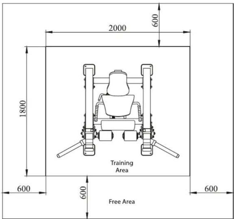
Specifications
Class: S
Maximum Wt. Capacity: 2*150kg/330lbs
Maximum User Weight: 150kg/330lbs
Product Total Surface: 1300*1697mm
Product Total Mass: 130.9kg/289lbs
Instructions
Before beginning assembly please take the time to read instructions thoroughly. Please use the various lists in this manual to make sure that all parts have been included in your shipment. When ordering, use part number and description from the lists. Use only our replacement part when servicing. Failure to do so will void your warranty and could result in personal injury.
The equipment is designed to provide the smoothest, most effective exercise motion possible. After assembly, you should check all functions to ensure correct operation. If you experience problems, first recheck the assembly instructions to locate any possible errors made during assembly. If you are unable to correct the problem, call your authorized dealer. Be sure to have your serial number and this manual when calling. When all parts have been accounted for, continue on.
Tools Required
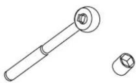
natural_image
Technical line drawing of a mechanical component with a cylindrical shaft and flanged end (no text or symbols)Ratchet Wrench and Socket
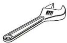
Adjustable Wrench
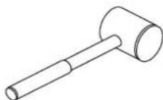
Rubber Mallet
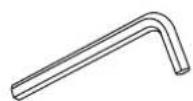
Hex Key Wrench Set
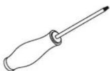
Phillips Screwdriver
Exploded View and Parts List
Adjust Handle ASSY
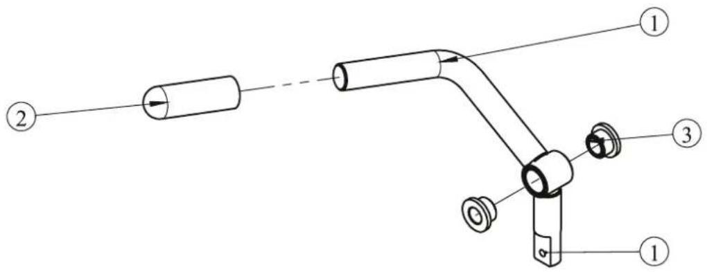
| ITEM NO. | Description | QTY |
| 1 | Adjust Handle Frame | 1 |
| 2 | Rubber Grip | 1 |
| 3 | Bushing | 2 |
Guide Rod ASSY
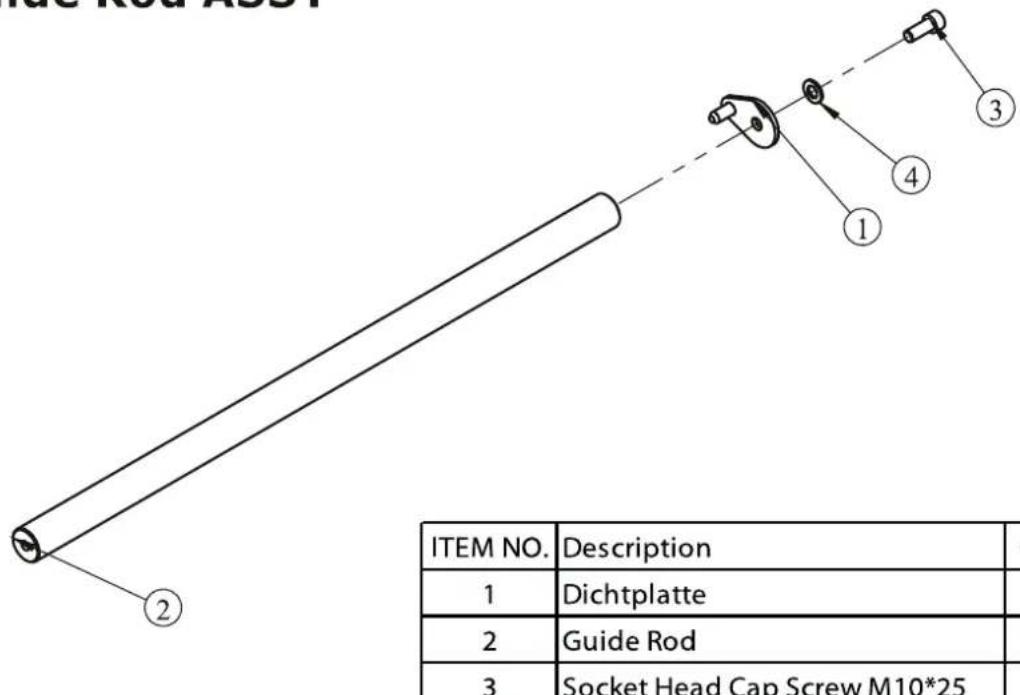
| ITEM NO. | Description | QTY |
| 1 | Dichtplatte | 1 |
| 2 | Guide Rod | 1 |
| 3 | Socket Head Cap Screw M10*25 | 1 |
| 4 | Flat Washer Φ 11*Φ 20*2 | 1 |
Exploded View and Parts List
Left Handle ASSY
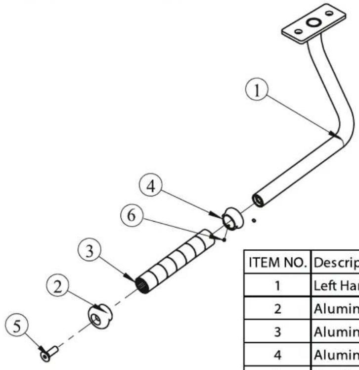
| ITEM NO. | Description | QTY |
| 1 | Left Handle | 1 |
| 2 | Aluminium Cap Φ25 | 1 |
| 3 | Aluminium Grip | 1 |
| 4 | Aluminium Ring Φ25 | 1 |
| 5 | Flat Head Cap Screw M10*30 | 1 |
| 6 | Socket Set Screw 10-32*3.2 | 2 |
Left Leg Frame ASSY
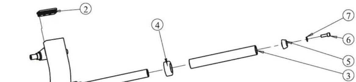
| ITEM NO. | Description | QTY |
| 1 | Left Leg Frame | 1 |
| 2 | Plug □ 50*100 | 1 |
| 3 | Long Weight Horn Sleeve | 1 |
| 4 | Rubber Bumper | 1 |
| 5 | Weight Horn Plastic Cap | 1 |
| 6 | Socket Head Cap Screw M12*35 | 1 |
| 7 | Flat Washer Φ 13*Φ 24*1.5 | 1 |
Exploded View and Parts List
Left Inside Bearing Fixed Plate ASSY
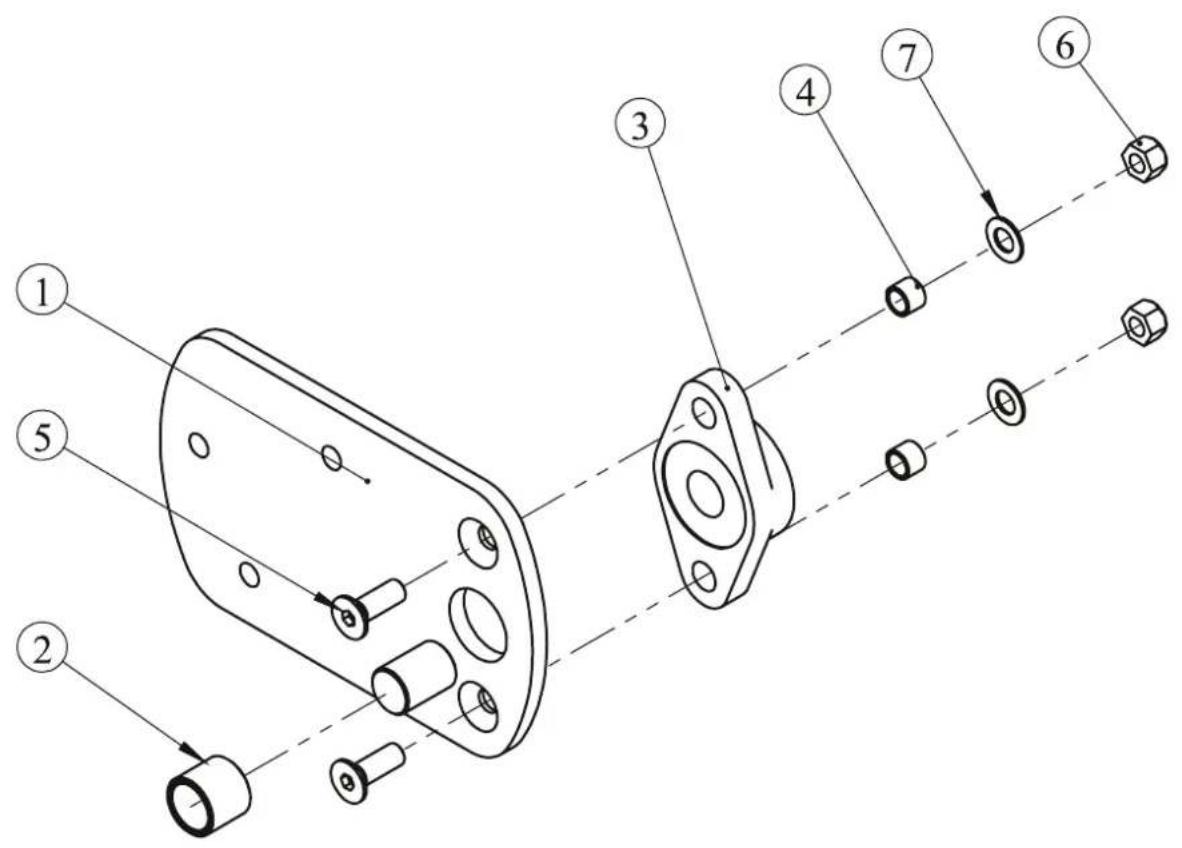
| ITEM NO. | Description | QTY |
| 1 | Left Inside Bearing Fixed Plate | 1 |
| 2 | Bumper | 1 |
| 3 | Pillow Block Bearing | 1 |
| 4 | Spacer Φ 16*Φ 12.2*12.5 | 2 |
| 5 | Flat Head Cap Screw M12*35 | 2 |
| 6 | Nylon lock Nut M12 | 2 |
| 7 | Flat Washer Φ 13*Φ 24*1.5 | 2 |
Exploded View and Parts List
Left Outside Bearing Fixed Plate ASSY
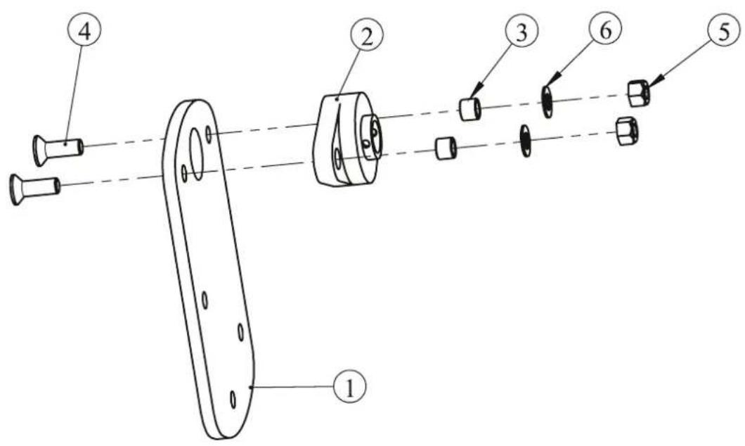
| ITEM NO. | Description | QTY |
| 1 | Left Outside Bearing Fixed Plate | 1 |
| 2 | Pillow Block Bearing | 1 |
| 3 | Spacer Φ 16*Φ 12.2*12.5 | 2 |
| 4 | Flat Head Cap Screw M12*35 | 2 |
| 5 | Nylon lock Nut M12 | 2 |
| 6 | Flat Washer Φ 13*Φ 24*1.5 | 2 |
Exploded View and Parts List
Left Upright Frame ASSY
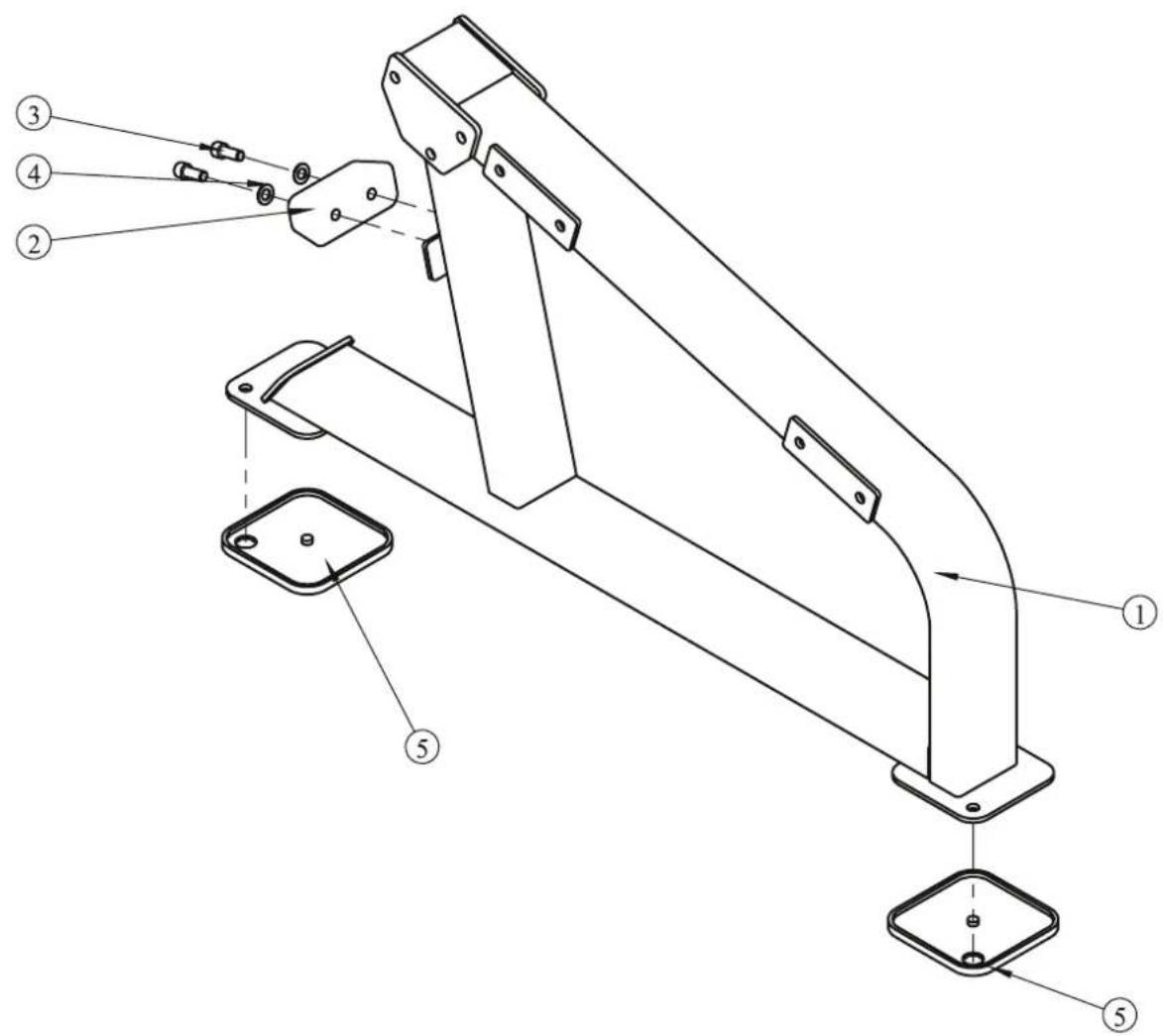
| ITEM NO. | Description | QTY |
| 1 | Left Upright Frame | 1 |
| 2 | Rubber Bumper 140*58*52 | 1 |
| 3 | Socket Head Cap Screw M12*30 | 2 |
| 4 | Flat Washer Φ13*Φ24*1.5 | 2 |
| 5 | Rubber Foot | 2 |
Moving Seat Pad Frame ASSY
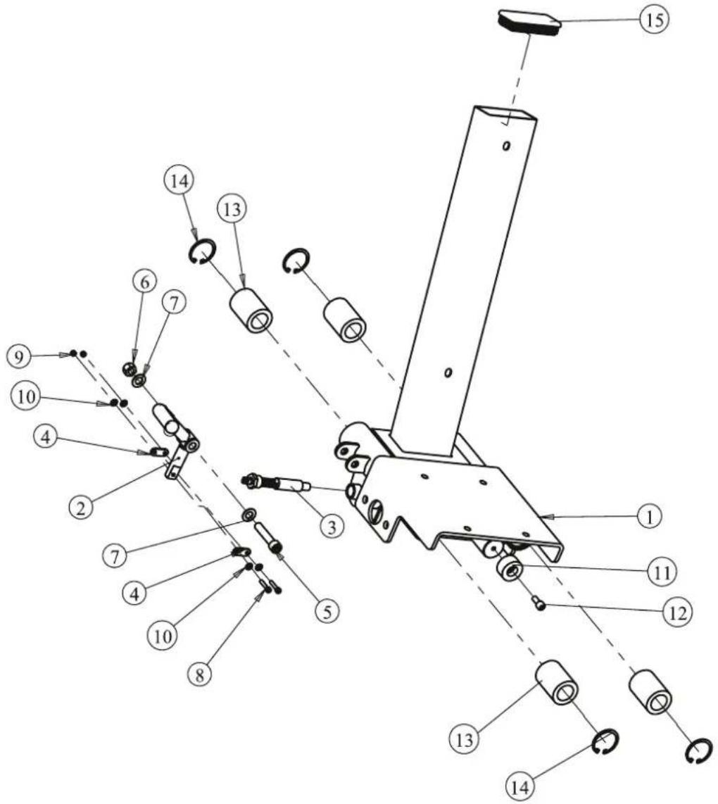
| ITEM NO. | Description | QTY | ITEM NO. | Description | QTY |
| 1 | Moving seat Pad Frame | 1 | 9 | Nylon lock Nut M12 | 2 |
| 2 | Adjust Handle ASSY | 1 | 10 | Flat Washer 5.5* 12*1 | 4 |
| 3 | Spring Pin | 1 | 11 | Rubber Bumper 38*19.5 | 1 |
| 4 | Plate | 2 | 12 | Socket Head Cap Screw M8*20 | 1 |
| 5 | Socket Head Cap Screw M12*60 | 1 | 13 | Linear Bearing 45* 30*64 | 4 |
| 6 | Nylon lock Nut M12 | 1 | 14 | Circlips for hole--Type A 45 | 4 |
| 7 | Flat Washer 13* 24*1.5 | 2 | 15 | Plug □ 50*100 | 1 |
| 8 | Socket Head Cap Screw M5*25 | 2 |
Exploded View and Parts List
Rear Link Frame ASSY
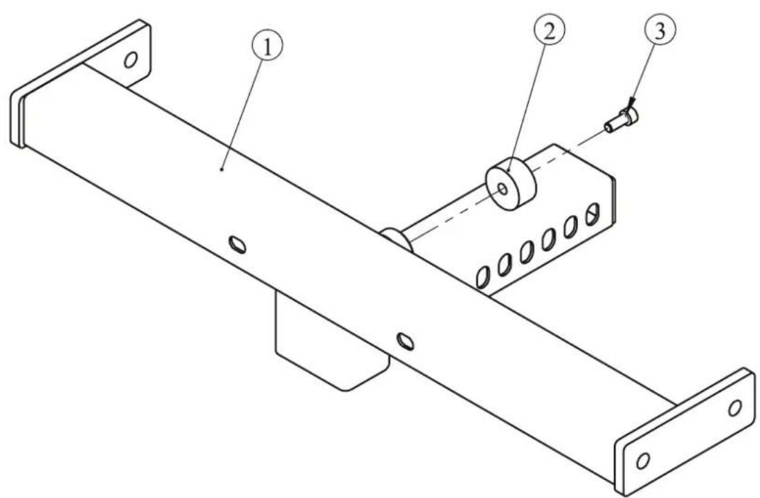
| ITEM NO. | Description | QTY |
| 1 | Rear Link Frame | 1 |
| 2 | Rubber Bumper Φ38*19.5 | 1 |
| 3 | Socket Head Cap Screw M8*20 | 1 |
Exploded View and Parts List
Right Handle ASSY
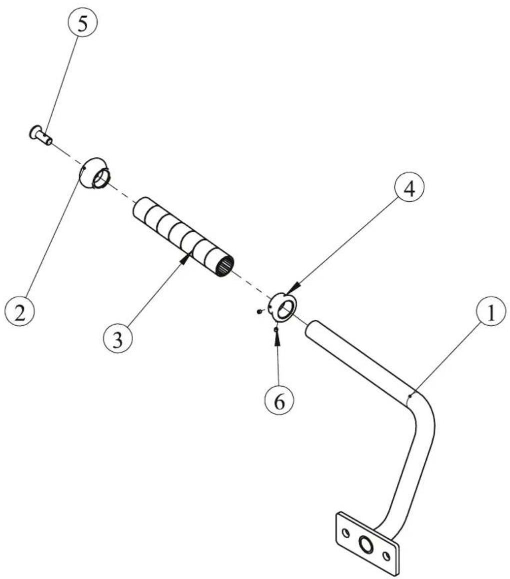
| ITEM NO. | Description | QTY |
| 1 | Right Handle | 1 |
| 2 | Aluminium Cap Φ25 | 1 |
| 3 | Aluminium Grip | 1 |
| 4 | Aluminium Ring Φ25 | 1 |
| 5 | Flat Head Cap Screw M10*30 | 1 |
| 6 | Socket Set Screw 10-32*3.2 | 2 |
Right Inside Bearing Fixed Plate ASSY
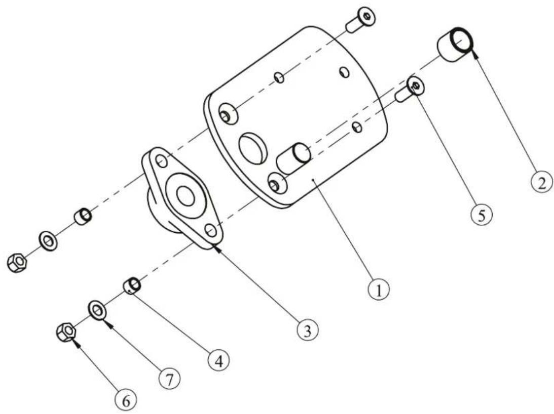
| ITEM NO. | Description | QTY |
| 1 | Right Inside Bearing Fixed Plate | 1 |
| 2 | Bumper | 1 |
| 3 | Pillow Block Bearing | 1 |
| 4 | Spacer Φ 16*Φ 12.2*12.5 | 2 |
| 5 | Flat Head Cap Screw M12*35 | 2 |
| 6 | Nylon lock Nut M12 | 2 |
| 7 | Flat Washer Φ 13*Φ 24*1.5 | 2 |
Exploded View and Parts List
Right Leg Frame ASSY
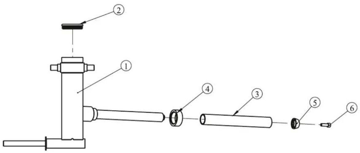
| ITEM NO. | Description | QTY |
| 1 | Right Leg Frame | 1 |
| 2 | Plug □ 50*100 | 1 |
| 3 | Long Weight Horn Sleeve | 1 |
| 4 | Rubber Bumper | 1 |
| 5 | Weight Horn Plastic Cap | 1 |
| 6 | Socket Head Cap Screw M12*35 | 1 |
| 7 | Flat Washer Φ 13*Φ 24*1.5 | 1 |
Right Outside Bearing Fixed Plate ASSY
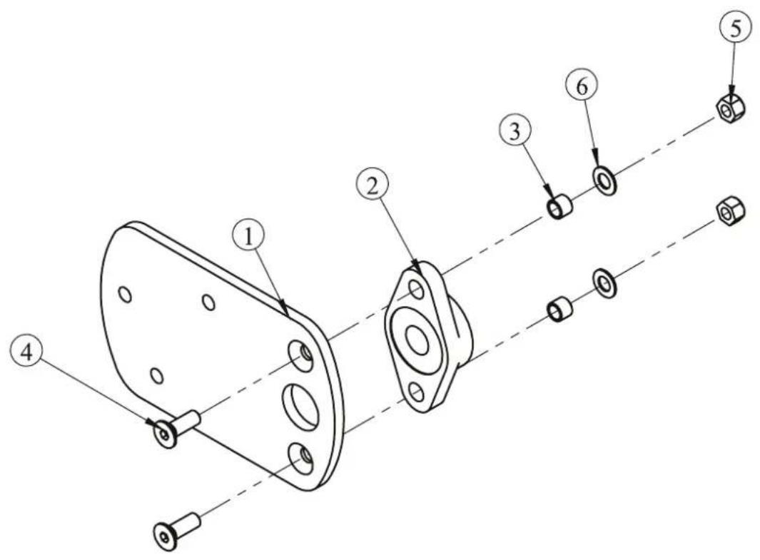
| ITEM NO. | Description | QTY |
| 1 | Right Outside Bearing Fixed Plate | 1 |
| 2 | Pillow Block Bearing | 1 |
| 3 | Spacer Φ 16*Φ 12.2*12.5 | 2 |
| 4 | Flat Head Cap Screw M12*35 | 2 |
| 5 | Nylon lock Nut M12 | 2 |
| 6 | Flat Washer Φ 13*Φ 24*1.5 | 2 |
Exploded View and Parts List
Right Upright Frame ASSY
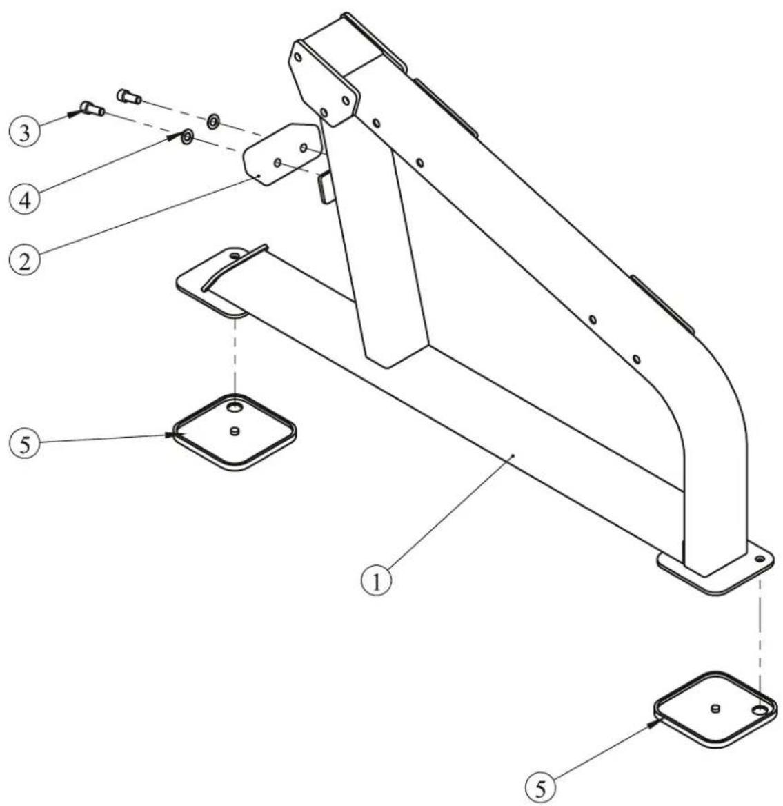
| ITEM NO. | Description | QTY |
| 1 | Right Upright Frame | 1 |
| 2 | Rubber Bumper 140*58*52 | 1 |
| 3 | Socket Head Cap Screw M12*30 | 2 |
| 4 | Flat Washer Φ13*Φ24*1.5 | 2 |
| 5 | Rubber Foot | 2 |
Overall
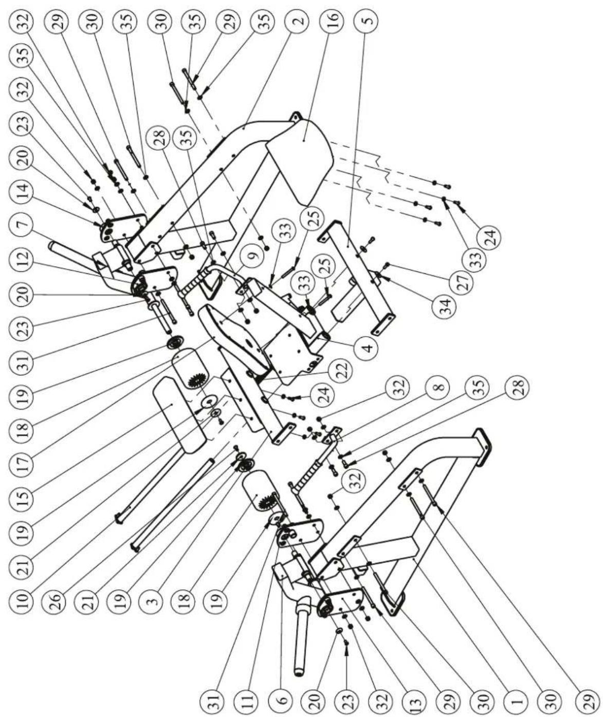
| ITEM NO. | Description | QTY | ITEM NO. | Description | QTY |
| 1 | Left Upright Frame ASSY | 1 | 19 | Aluminium Ring Φ 90 | 4 |
| 2 | Right Upright Frame ASSY | 1 | 20 | Small Domed Cap | 4 |
| 3 | Front seat Pad Frame WeLding ASSY | 1 | 21 | Domed Aluminium Cap | 2 |
| 4 | Moving seat Pad Frame ASSY | 1 | 22 | Extension Spring | 1 |
| 5 | Rear Link Frame ASSY | 1 | 23 | Button Head Cap Screw M10*20 | 4 |
| 6 | Left Leg Frame ASSY | 1 | 24 | Button Head Cap Screw M10*30 | 7 |
| 7 | Right Leg Frame ASSY | 1 | 25 | Button Head Cap Screw M10*75 | 2 |
| 8 | Left Handle ASSY | 1 | 26 | Flat Head Cap Screw M10*25 | 2 |
| 9 | Right Handle ASSY | 1 | 27 | Socket Head Cap Screw M10*25 | 2 |
| 10 | Guide Rod ASSY | 2 | 28 | Socket Head Cap Screw M12*30 | 4 |
| 11 | Left Inside Bearing Fixed Plate ASSY | 1 | 29 | Socket Head Cap Screw M12*130 | 4 |
| 12 | Right Inside Bearing Fixed Plate ASSY | 1 | 30 | Socket Head Cap Screw M12*135 | 4 |
| 13 | Left Outside Bearing Fixed Plate ASSY | 1 | 31 | Socket Head Cap Screw M12*155 | 6 |
| 14 | Right Outside Bearing Fixed Plate ASSY | 1 | 32 | Nylon lock Nut M12 | 14 |
| 15 | Front Seat Pad | 1 | 33 | Flat Washer Φ 11*Φ 20*2 | 9 |
| 16 | Rear Seat Pad | 1 | 34 | Flat Washer Φ 11*Φ 38*2 | 2 |
| 17 | Back Pad | 1 | 35 | Flat Washer Φ 13*Φ 24*1.5 | 32 |
| 18 | FOAM | 2 |
Exploded View and Parts List
Overall
Measurement Guide
bar
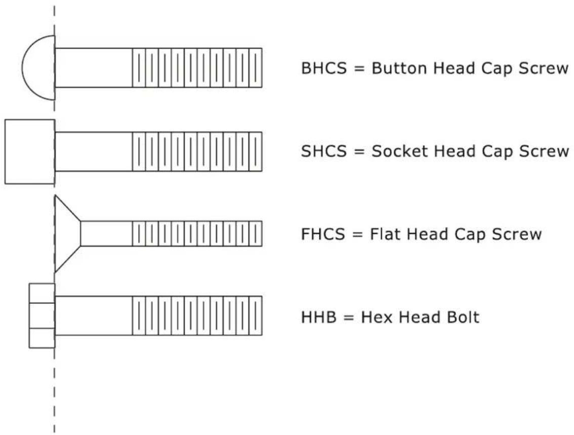
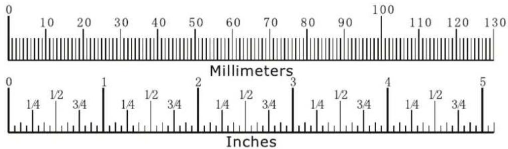
| Millimeters | Inches | |---|---| | 0 | 0 | | 10 | 1/4 | | 20 | 1/2 | | 30 | 3/4 | | 40 | 1/4 | | 50 | 1/2 | | 60 | 3/4 | | 70 | 1/4 | | 80 | 1/2 | | 90 | 3/4 | | 100 | 4 | | 110 | 1/4 | | 120 | 1/2 | | 130 | 3/4 | | (top label) | Millimeters (0–130) | | (bottom label) | (0–5) (5) || Diameter of bolt (mm/inch) | M6(1/4") | M8(5/16") | M10(3/8") | M12(1/2") | M16(5/8") |
| Tightening torque (N.m) | 9~12 | 22~30 | 45~59 | 78~104 | 193~257 |
| Operational methods for adult men | The strength of the wrist | The strength of the wrist and forearm | The strength of the entire arm | The strength of the arm and upper body | with all strength |
Assembly Instructions
Assembly of the equipment takes professional installers about 2 hours. If this is the first time you have assembled this type of equipment, plan to spend more time. It is strongly recommended to assemble the equipment by professional installers. You may find it quicker, safer, easier to assemble this equipment with the help of a friend, as some of components may be large, heavy or awkward to handle alone. It is important that you assemble your product in a clean, clear, uncluttered area. This will enable you to move around the product while you are fitting components and reduce the possibility of injury during assembly.

NOTE
As with any assembled part, proper alignment and adjustment is critical. While tightening the fasteners, be sure to leave room for adjustments. Do not fully tighten the fasteners until instructed to do so. Be careful to assemble the components in the sequence presented in this guide.
Assembly
STEP 1
- Attach the Front Seat Pad Frame Welding ASSY (#3) to the Left Upright Frame ASSY (#1) and Right Upright Frame ASSY (#2), using:
• two M12*130 SHCS (#29)
• two M12*135 SHCS (#30)
• two M12 Nylon lock Nuts (#32)
• six Φ13*Φ24*1.5 Flat Washers (#35)
- Attach the Rear Link Frame ASSY (#5) to the Left Upright Frame ASSY (#1) and Right Upright Frame ASSY (#2), using:
• two M12*130 SHCS (#29)
• two M12*135 SHCS (#30)
• two M12 Nylon lock Nuts (#32)
• six Φ13*Φ24*1.5 Flat Washers (#35)
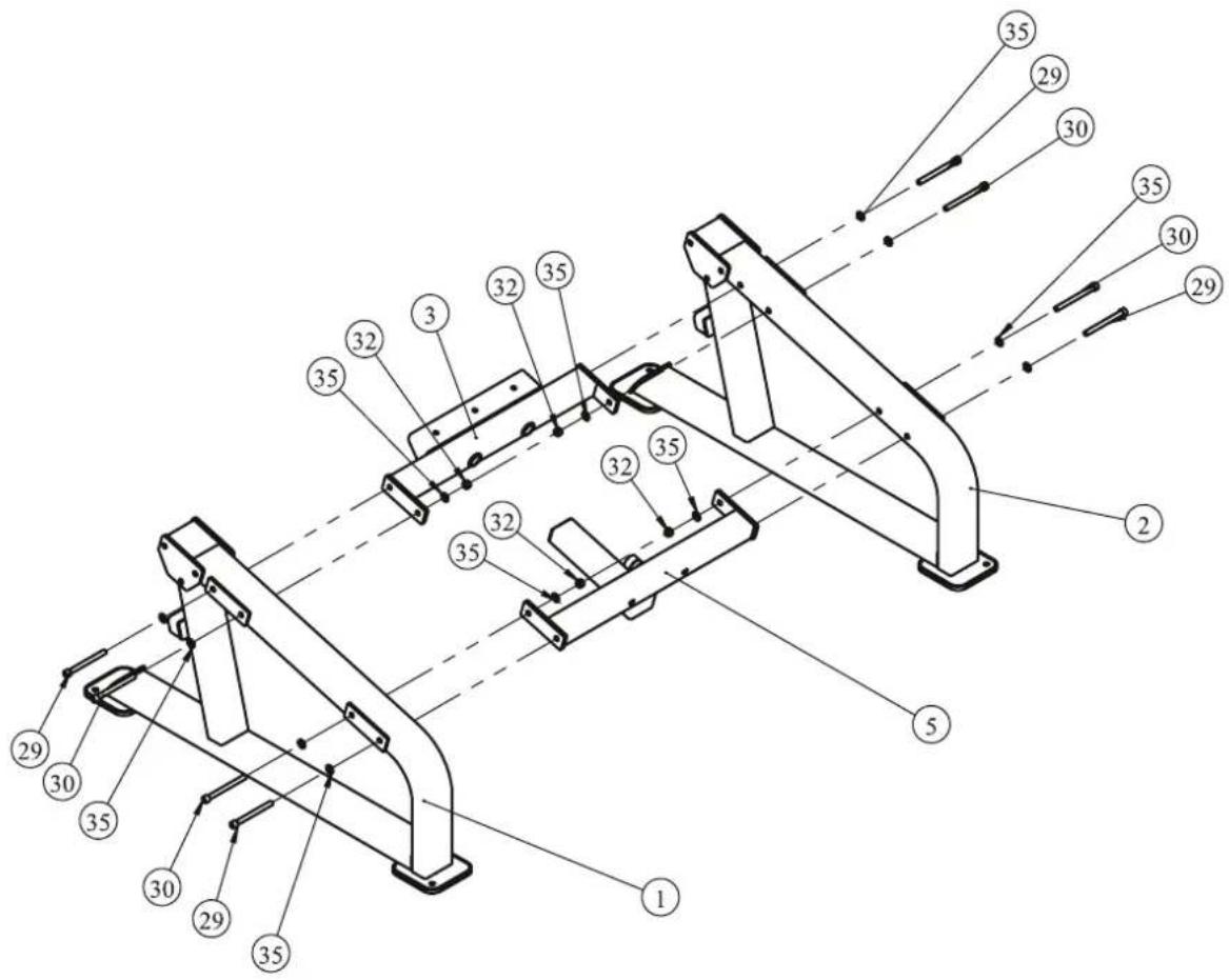
Assembly
STEP 2
Attach the Left Handle ASSY (#8) and Right Handle ASSY (#9) to two sides of the Moving Seat Pad Frame ASSY (#4), using:
• four M12*30 SHCS (#28)
• four M12 Nylon lock Nuts (#32)
• eight Φ13*Φ24*1.5 Flat Washers (#35)
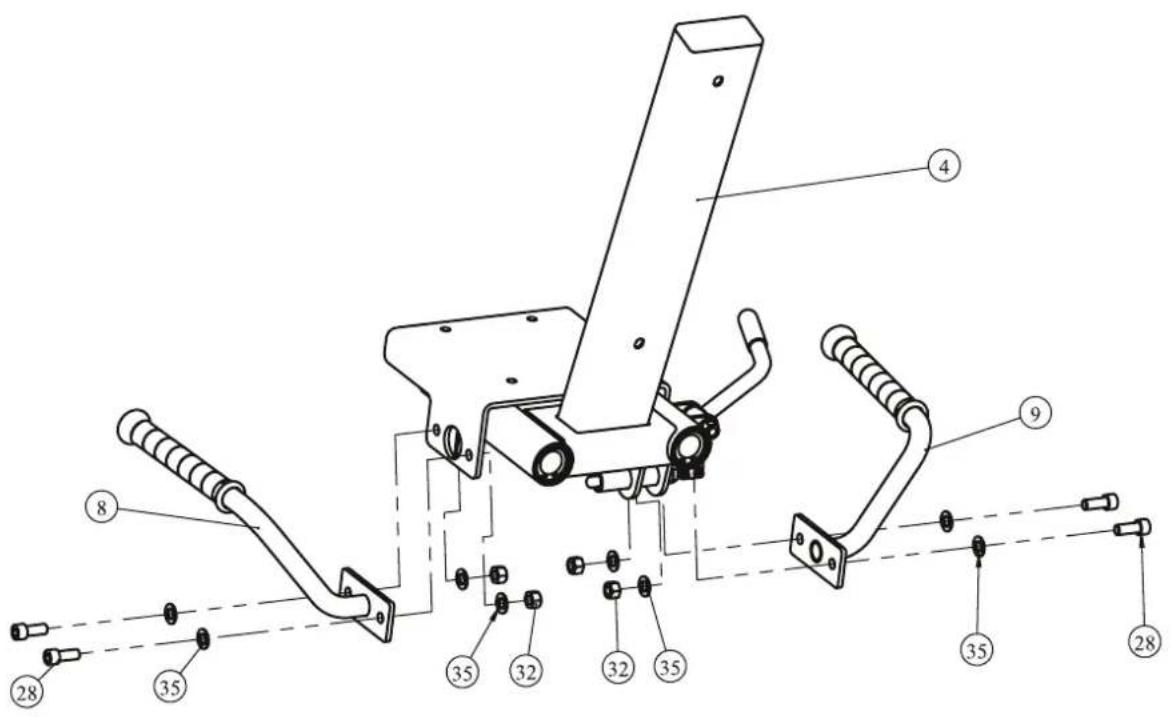
Assembly
STEP 3
Attach two Guide Rod ASSY (#10) and Moving Seat Pad Frame ASSY (#4) to the Front Seat Pad Frame WeLding ASSY (#3) and Attach Rear Link Frame ASSY (#5), using:
• two M10*25 SHCS (#27)
• two Φ11*Φ38*2 Flat Washers (#34)
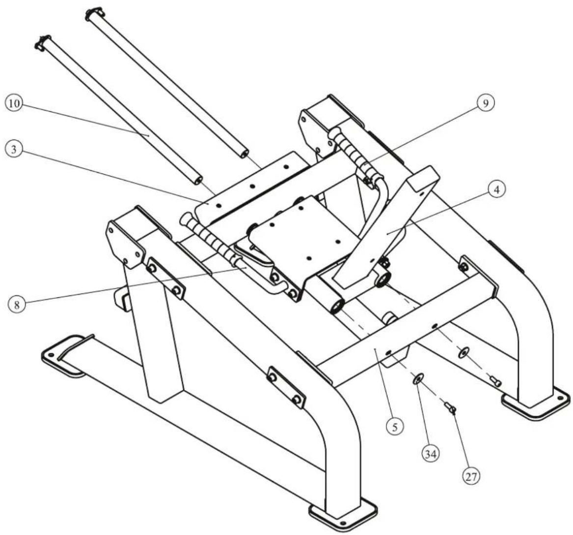
Assembly
STEP 4
- Attach the Left Leg Frame ASSY (#6), Left Inside Bearing Fixed Plate ASSY (#11) and Left Outside Bearing Fixed Plate ASSY (#13) to the Left Upright Frame ASSY (#1), using:
• three M12*155 SHCS (#31)
• three M12 Nylon lock Nuts (#32)
• six Φ13*Φ24*1.5 Flat Washers (#35)
- Attach the Right Leg Frame ASSY (#7), Right Inside Bearing Fixed Plate ASSY (#12) and Right Outside Bearing Fixed Plate ASSY (#14) to the Right Upright Frame ASSY (#2), using:
• three M12*155 SHCS (#31)
• three M12 Nylon lock Nuts (#32)
• six Φ13*Φ24*1.5 Flat Washers (#35)
- Attach four Small Domed Caps (#14) to the Left Leg Frame ASSY (#6) and Right Leg Frame ASSY (#7), using:
• four M10*20 BHCS (#23)
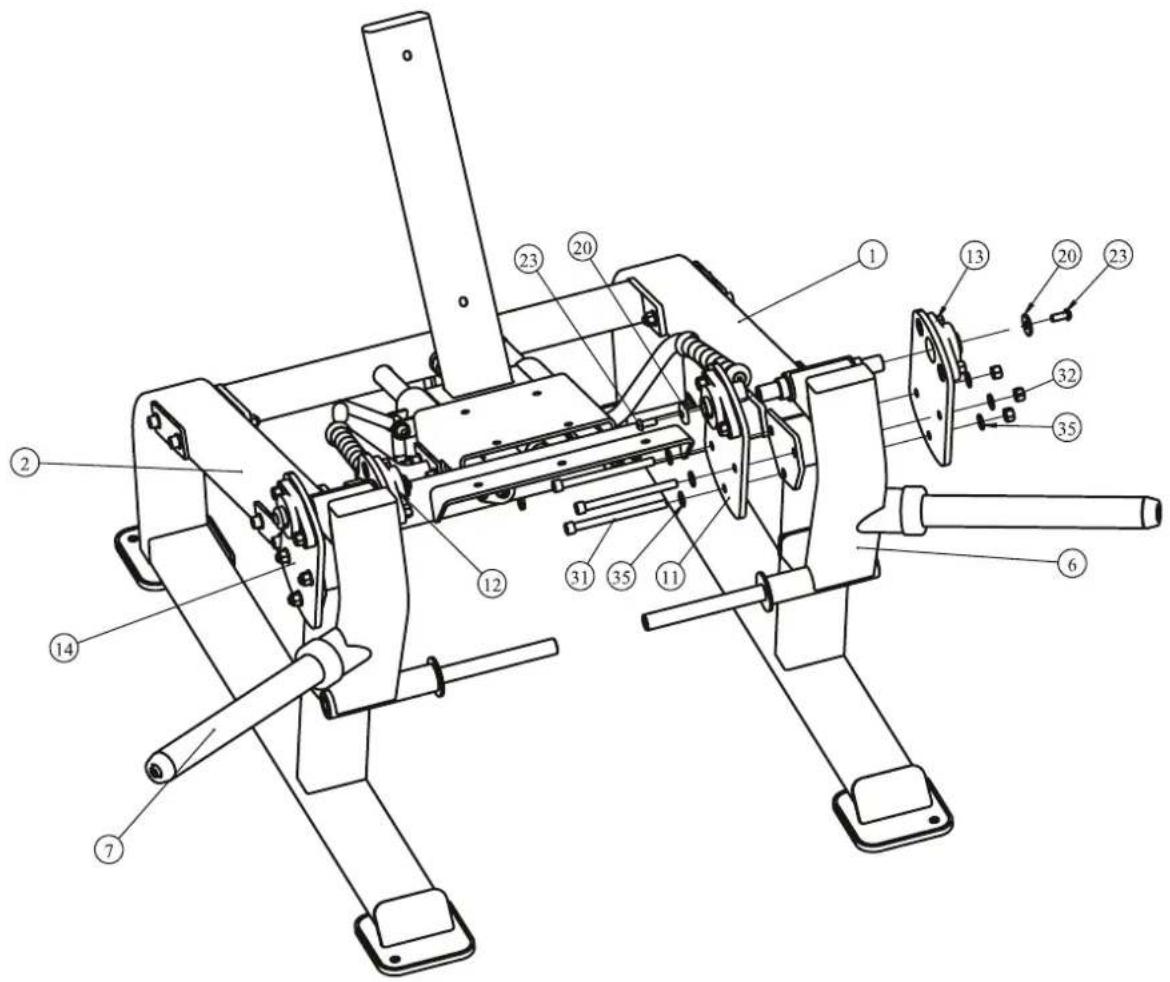
Assembly
STEP 5
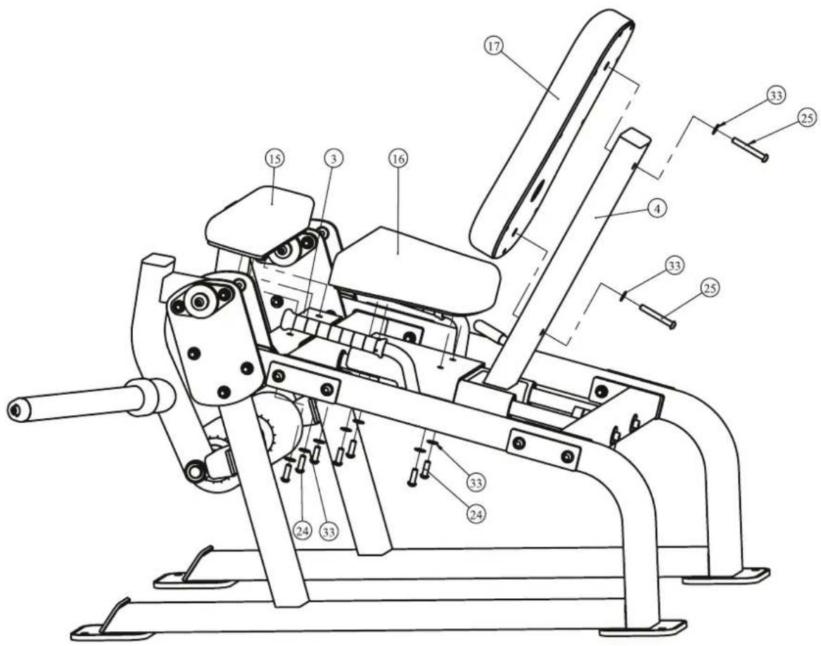
- Attach the Front Seat Pad (#15) to the Front Seat Pad Frame WeLding ASSY (#3), using:
• three M10*30 BHCS (#24)
• three Φ11*Φ20*2 Flat Washers (#33)
- Attach the Rear Seat Pad (#16) to the Moving Seat Pad Frame ASSY (#4), using:
• four M10*30 BHCS (#24)
• four Φ11*Φ20*2 Flat Washers (#33)
- Attach the back Pad (#17) to the Moving Seat Pad Frame ASSY (#4), using:
• two M10*75 BHCS (#25)
• two Φ11*Φ20*2 Flat Washers (#33)
Assembly
STEP 6
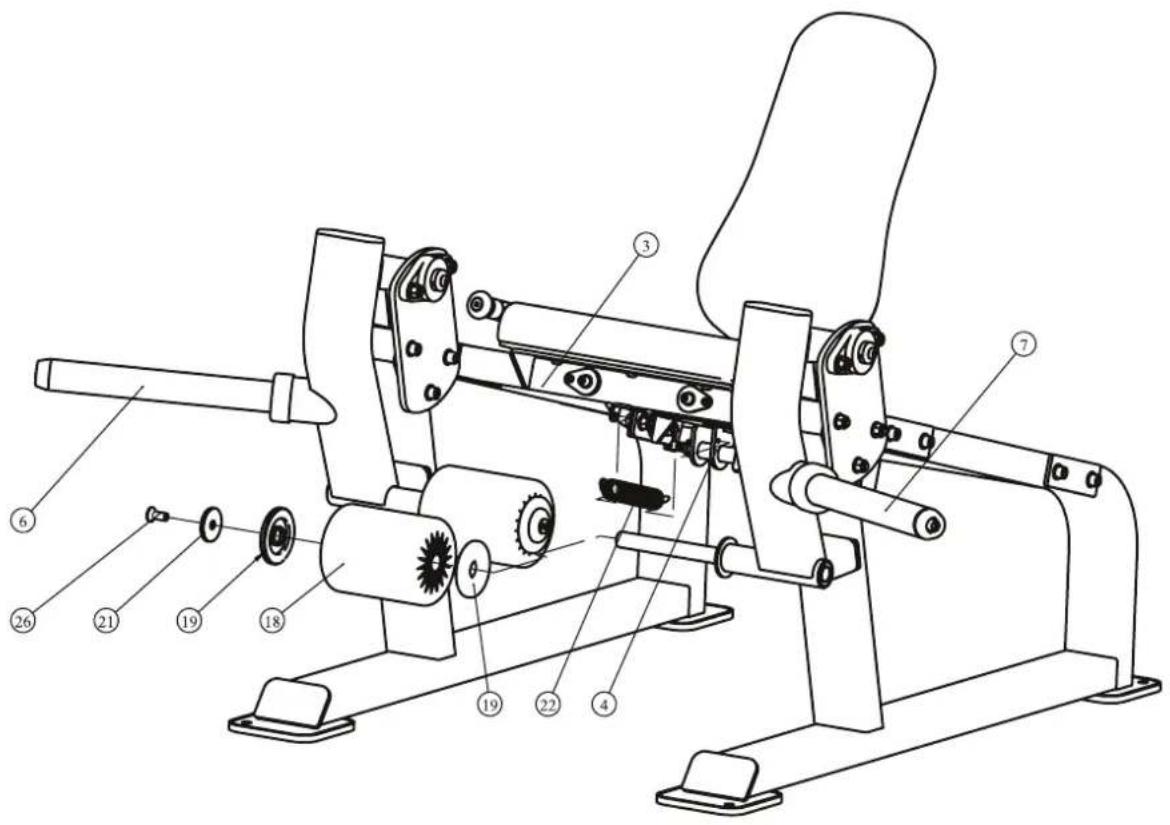
- Attach two Foams (#18) to t the Left Leg Frame ASSY (#6) and Right Leg Frame ASSY (#7), using:
• four Φ90 Aluminium Rings (#19)
• two Domed Aluminium Caps (#21)
• two M10*25 THCS (#26)
- Attach the Extension Spring (#22) to the Front Seat Pad Frame WeLding ASSY (#3) and the Moving Seat Pad Frame ASSY (#4).
Note: Hand tighten bolts and Nylon Lock Nuts until machine is fully assembled.
Adjust Instructions
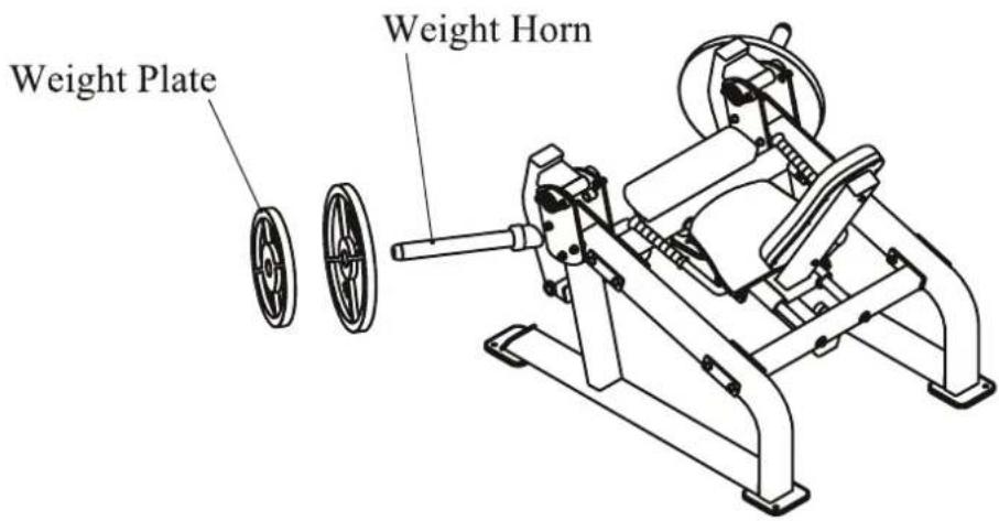
Weight Plate Installation Requirements
- Please use Olympic Weight Plate which hole is greater than 50mm and external diameter is less than 500mm .
- The total weight of one side can not be greater than 150kg.
- This equipment does not contains Weight Plate.
Seat Pad adjustment
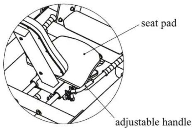
- Pull the adjustable handle, move the seat pad to desired position, and then release the handle.
- Make sure the pin gets into the hole completely.
Exercise Instructions
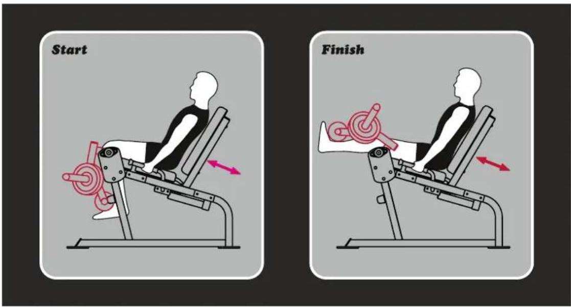
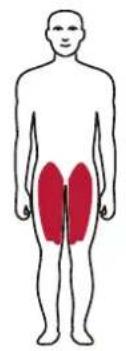
natural_image
Human body diagram with two red shaded regions on the lower abdomen (no text or labels)Exercise Instructions
- Select an appropriate weight.
- Adjust seat pad to the desired position.
- Hook both ankles under the roller pads, then extend legs outward.
- Pause slightly then slowly return to the starting position.
Maintenance Schedule
| ROUTINE | COMMERCIAL MAINTENANCE | HOME MAINTENANCE | LATEST DATE ENTRY | ||||||
| Inspect; Links, Pull Pins, Snap Locks, Swivels, Weight Stack Pins | DAILY | WEEKLY | |||||||
| Clean; Upholstery | DAILY | WEEKLY | |||||||
| Inspect; Cables or Belts and their tension | DAILY | WEEKLY | |||||||
| Inspect; Accessory Bars, and Handles | WEEKLY | 3 MONTHS | |||||||
| Inspect; All Decals | WEEKLY | 3 MONTHS | |||||||
| Inspect; All Nuts and Bolts, Tighten if needed | WEEKLY | 3 MONTHS | |||||||
| Inspect; Anti-Skid Surface | WEEKLY | 3 MONTHS | |||||||
| Clean & Lubricate; Guide Rods with a Teflon (PTFE) based lubricant (Superlube) | MONTHLY | 3 MONTHS | |||||||
| Lubricate; Seat Sleeves, Turcite Bushings, Linear Bearing | MONTHLY | 3 MONTHS | |||||||
| Clean and Wax; All Glossy Finishes | 6 MONTHS | YEARLY | |||||||
| Repack with Grease; Linear Bearings | 6 MONTHS | YEARLY | |||||||
| Replace; Cables, Belts and Connecting Parts | YEARLY | 3 YEARS | |||||||
Your equipment comes with a commercial maintenance decal. For personal, in home use, please follow the home maintenance schedule listed above.
General Maintenance Information
Links, Pull-Pins, Snap Hooks, Swivels, Weight Stack Pins:
* Check all pieces for signs of visible wear or damage.
* Check springs in snap hooks and pull-pins for proper tension and alignment.
* If the spring sticks or has lost its rigidity, replace it immediately.
Upholstery:
* To ensure prolonged upholstery life and proper hygiene, all upholstered pads should be wiped down with a damp cloth after every workout.
* Periodically take the time to use a mild soap or an approved vinyl upholstery cleaner to deter the onset of cracking or drying. Avoid using any abrasive cleaners or cleaners not intended for use on vinyl.
* Replace ripped or warn upholstery immediately.
* Keep sharp or pointed objects clear of all upholstery.
Decals:
* Inspect and familiarize yourself with any safety warnings or other user information posted on each decal.
Nuts and Bolts:
* Inspect all nuts and bolts for any loosening and tighten if needed.
* Go through a re-tightening sequence periodically to ensure that all hardware is tensioned proper.
Anti-Skid Surfaces:
* These surfaces are designed to supply secure footing and need to be replaced if they appear worn or become slippery.
Belts and Cables:
* We uses only high quality belt, and mil-spec cables.
* Visually inspect the belts and cables for fraying, cracking, peeling or discoloration.
* While the machine is not in use, carefully run your fingers along the belt or cable to feel for thinning or bulging areas.
* Replace belts and cables immediately at the first signs of damage or wear. Do not use equipment until belts or cables have been replaced.
Belt and Cable Tension:
* Referring to the Owners Manual, when belts or cables are used check all bolts attachments to be sure they are properly attached.
* Check slack in cables and re-adjust cable tension if needed.
Seat Sleeves, Guide Rods:
* Wipe down adjusting tubes with a dust free rag before applying lubricant.
* Lubricate seat sleeves and Guide Rods with a Silicon or Teflon based lubricant spray.
Linear Bearings:
* Referring to the Owners Manual carefully disassemble the bearing from its housing and place a finger full of light grease (lithium, super lube, etc.) into the inside of the bearing. Using your finger, press the grease into the ball-bearings and their tracks. repeat until the ball-bearing tracks are full of grease. Insert the shaft back into the bearing and wipe off excess grease.
PLEASE KEEP THIS FOR YOUR RECORDS
Weight Training Tips
Use this manual to guide you through the basic exercises you can perform on your equipment. To gain maximum results and avoid possible injury, consult a fitness professional to develop your complete exercise program.
Always consult your physician before starting any exercise program.
To be successful in your exercise program, it is important to develop an understanding of the basic principles of strength training. Now that you have your equipment, it is only natural that you want to get started immediately. First, determine a set of realistic goals and objectives for yourself. By deciding on an exercise plan that is right for you prior to starting, you will contribute significantly to your success.
Warm up properly before engaging in weight resistance training. Stretching, yoga, jogging, calisthenics or other cardiovascular exercise can help prepare your body for the heavier workload of lifting weights.
Learn how to perform the exercise correctly before using heavy weight. Correct form is important to avoid injury and to ensure that you work the proper muscle groups.
Know your limitations. If you are new to weight training or are embarking on an exercise regimen after a long layoff, start slowly and build foundational strength over a longer period of time.
Pay attention to your breathing. Exhale when you exert is a general rule of thumb. Never hold your breath.


- TAURUS®
- ! CAUTION
- Table Of Contents
- Important Safety Instructions
- Personal Safety During Assembly
- Training Area and Free Area
- Specifications
- Instructions
- Tools Required
- Exploded View and Parts List
- Left Inside Bearing Fixed Plate ASSY
- Left Outside Bearing Fixed Plate ASSY
- Left Upright Frame ASSY
- Rear Link Frame ASSY
- Right Inside Bearing Fixed Plate ASSY
- Right Leg Frame ASSY
- Right Outside Bearing Fixed Plate ASSY
- Measurement Guide
- Assembly Instructions
- NOTE
- Assembly
- STEP 1
- STEP 2
- STEP 3
- STEP 4
- STEP 5
- STEP 6
- Adjust Instructions
- Weight Plate Installation Requirements
- Seat Pad adjustment
- Exercise Instructions
- Maintenance Schedule
- General Maintenance Information
- Links, Pull-Pins, Snap Hooks, Swivels, Weight Stack Pins:
- Upholstery:
- Decals:
- Nuts and Bolts:
- Anti-Skid Surfaces:
- Belts and Cables:
- Belt and Cable Tension:
- Seat Sleeves, Guide Rods:
- Linear Bearings:
- PLEASE KEEP THIS FOR YOUR RECORDS
- Weight Training Tips
Marke : TAURUS
Modell : Iso Leg Extension Sterling
Kategorie : Fitnessgeräte