
4005 - Nicht kategorisiert MILWAUKEE - Kostenlose Bedienungsanleitung
Finden Sie kostenlos die Bedienungsanleitung des Geräts 4005 MILWAUKEE als PDF.


| Produkttyp | Ladegerät |
| Marke | Milwaukee |
| Modell | 4005 |
| Kompatible Akkus | Milwaukee M12 (12V) |
| Eingangsspannung | 220-240 V AC |
| Eingangsfrequenz | 50/60 Hz |
| Ausgangsspannung | 12 V DC |
| Ausgangsstrom | 2 A |
| Ladezeit | ca. 30-60 min (je nach Akkukapazität) |
| LED-Anzeige | Ladezustand und Fehlermeldungen |
| Schutzfunktionen | Überladeschutz, Kurzschlussschutz, Temperaturüberwachung |
| Abmessungen (L x B x H) | 120 x 100 x 70 mm |
| Gewicht | 0,3 kg |
| Gehäusematerial | Kunststoff |
| Betriebstemperatur | 0 °C bis 40 °C |
| Lagertemperatur | -20 °C bis 65 °C |
| Luftfeuchtigkeit | max. 95 % (nicht kondensierend) |
| Reinigung | Mit einem trockenen Tuch abwischen; nicht in Wasser tauchen |
| Wartung | Keine vom Benutzer wartbaren Teile |
| Sicherheitshinweise | Nur in Innenräumen verwenden; vor Feuchtigkeit schützen |
| Zertifizierungen | CE, RoHS |
| Lieferumfang | Ladegerät, Bedienungsanleitung |
Häufig gestellte Fragen - 4005 MILWAUKEE
Benutzerfragen zu 4005 MILWAUKEE
0 Frage zu diesem Gerät. Beantworten Sie die, die Sie kennen, oder stellen Sie Ihre eigene.
Eine neue Frage zu diesem Gerät stellen
Laden Sie die Anleitung für Ihr Nicht kategorisiert kostenlos im PDF-Format! Finden Sie Ihr Handbuch 4005 - MILWAUKEE und nehmen Sie Ihr elektronisches Gerät wieder in die Hand. Auf dieser Seite sind alle Dokumente veröffentlicht, die für die Verwendung Ihres Geräts notwendig sind. 4005 von der Marke MILWAUKEE.
BEDIENUNGSANLEITUNG 4005 MILWAUKEE
| SPECIFY CATALOG NO. AND SERIAL NO. WHEN ORDERING PARTS | REVISED BULLETIN DATE | ||
| DYMODRILL with INTERNAL CLUTCH | Mar. 2008 | ||
| CATALOG NO. 4005 | STARTING SERIAL NO. 865A or 865B | WIRING INSTRUCTION58-01-0930 | |

EXAMPLE:
Component Parts (Small #)
Are Included When Ordering
The Assembly (Large #).
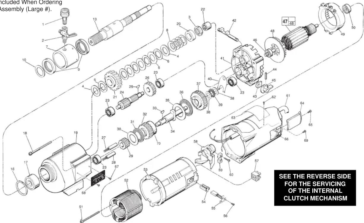
FIG. PART NO. DESCRIPTION OF PART NO. REQ.
| 1 | 42-04-0600 | Water Hose Adapter (1) | |
| 2 | 45-80-0060 | Shut Off Valve (1) | |
| 3 | 06-57-1050 Retaining Nut (1) | ||
| 4 | 45-88-1140 Thrust Washer (2) | ||
| 5 | 43-06-0160 Clutch Disc-Outer (3) | ||
| 6 | 43-06-0150 Clutch Disc-Inner (5) | ||
| 7 | 43-76-0051 Water Swivel Hsg Incl 06-83-2430 Scr (1) | ||
| 8 | 40-50-2150 Disc Spring (4) | ||
| 9 | 45-06-0635 Seal (2) | ||
| 10 | 45-88-8565 Washer (1) | ||
| 13 | 38-50-6020 Spindle (1) | ||
| 6 | 34-80-3800 Retaining Ring (1) | ||
| 7 | 02-20-2515 Ball Bearing (1) | ||
| 8 | 06-82-9202 1/4-20 x 4-1/4" Taptite T-30 (4) | ||
| 9 | 28-14-1870 Gear Case Assy., Incl 06-65-1535 Pin (1) | ||
| 10 | 45-36-1520 Spindle Spacer (1) | ||
| 11 | 32-75-3440 Spindle Gear (1) | ||
| 12 | 02-50-4830 Needle Bearing (1) | ||
| 13 | 02-04-1205 Ball Bearing (4) | ||
| 14 | 36-66-3751 Pinion Shaft Assy. (1) | ||
| 15 | 06-42-1600 Woodruff Key (1) | ||
| 16 | 32-40-1581 Intermediate Gear (1) | ||
| 17 | 40-50-6300 Shifting Spring (2) | ||
| 18 | 44-70-0100 Shifting Plunger (2) | ||
| 19 | 32-60-2011 Pinion Gear (1) | ||
| 20 | 45-88-0520 Thrust Bearing Washer (1) | ||
| 21 | 02-80-1800 Thrust Bearing (1) | ||
| 22 | 32-10-0060 Clutch Gear Assembly (1) | ||
| 23 | 06-42-2000 Woodruff Key (1) | ||
| 24 | 36-14-0061 Clutch Shaft (1) | ||
| 25 | 45-88-0530 Thrust Bearing Washer (1) | ||
| 26 | 02-80-5000 Thrust Bearing (1) | ||
| 27 | 32-10-0051 Clutch Gear Assembly (1) | ||
| 28 | 45-88-0510 Thrust Bearing Washer (2) | ||
| 29 | 02-80-1200 Thrust Bearing (1) | ||
| 30 | 45-98-0090 Shifting Yoke (1) | ||
| 31 | 14-13-0210 Diaphragm Assy., Incl 06-65-1155 Pin (1) | ||
| 32 | 30-15-0272 Shift Cam (1) | ||
| 33 | 43-44-0580 Foam Gasket (2) | ||
| 34 | 06-65-0840 1/8 x 3/4" Groove Pin (1) | ||
| 35 | 25-60-0056 Shifting Knob (1) | ||
| 36 | 02-04-1229 Ball Bearing (1) | ||
| 37 | 16-70-0320 120 V Armature (1) |
| FIG. | PART NO. | DESCRIPTION OF PART | NO. REQ. |
| 48 | 22-84-0790 | Fan | (1) |
| 49 | 42-14-0291 | Bafie | (1) |
| 50 | 02-04-1041 | Ball Bearing | (1) |
| 51 | 06-82-9152 | 10-24 x 2-3/4" Pan Hd. Sem. T-25 | (2) |
| 52 | 18-70-0290 | 120 V. Field | (1) |
| 53 | 23-16-1410 | Motor Insulator | (1) |
| 54 | 22-20-0680 | Brush Tube | (2) |
| 55 | 22-18-0702 | Carbon Brush Assembly | (2) |
| 56 | 06-82-8835 | 8-32 x 5/16" Pan Hd. Sem.T-20 | (2) |
| 57 | 22-56-0470 | Terminal Block | (1) |
| 58 | 22-38-0140 | Wire Trap | (1) |
| 59 | 31-17-0200 | Cord Clamp | (1) |
| 60 | 06-82-7326 | 8-16 x 1" Pan Hd. Plastite T-20 | (2) |
| 61 | 22-64-0300 | Cord Set | (1) |
| 62 | 06-72-1720 | Service Rivet | (2) |
| 63 | 12-99-1875 | Service Nameplate | (1) |
| 64 | 22-32-0350 | Brush Cover | (2) |
| 65 | 06-82-5316 | 8-32 x 1/2" Pan Hd. Slt. Taptite T-20 | (2) |
| 66 | 28-50-6363 | Motor Housing | (1) |
| 67 | 06-82-5266 | 4-40 x 1/4" Pan Hd. TaptiteT-10 | (2) |
| 68 | 12-98-2100 | Instruction Plate | (1) |
| 69 | 06-95-5200 | 8-32 x 5/16" Slotted Hex Hd. Screw | (1) |
| 70 | 45-36-0225 | Gear Spacer | (1) |
| 49-96-4700 | 1-3/8" Open End Wrench | (1) | |
| 45-88-0800 | Water Hose Washer (For Fig. No. 1) | (1) | |
| 61-10-0660 | Retaining Nut Spanner Tool | (1) | |
| 61-30-0061 | Water Seal Jig | (1) |
FOR MOUNTING DRILL MOTOR USE:
| 06-75-3090 | 1/4-20 x 7/8" Socket Hd. Screw | (4) |
| 06-97-4050 | 1/4" Split Ring Lock Washer | (4) |
FIG. LUBRICATION
19 18 Oz. Type "J" Grease, No. 49-08-4220
Servicing the Clutch Mechanism-
Torque Value for the Clutch Mechanism Retaining Nut (fig. no. 3).
Grease / Lubrication — when assembling the internal clutch component parts:
the Clutch Discs (fig. nos. 5 and 6), Thrust Washers (fig. no. 4) and
Disc Springs (fig. no. 8) are to be lightly coated with grease
(Cat. No. 49-08-4220 type 'J') during their assembly
into the spindle gear.
Grease / Lubrication specifi cation includes coating internal bore of the spindle gear.
4 45-88-1140 Thrust Washers (2)
5 43-06-0160 Clutch Discs-Outer (3)
6 43-06-0150 Clutch Discs-Inner (5)
8 40-50-2150 Spring Discs (4)
32-75-3430 Spindle Gear (1)
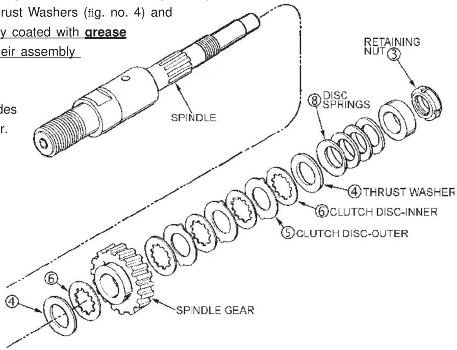
Service note: the assembly torque for the Clutch Mechanism Retaining Nut, No. 06-57-1050 (fig. no. 3), which insures the static torque required to slip the clutch mechanism, as lubricated, should be 25-30 ft-lbs.
With the gear case separated from the diaphragm & motor housing of the Clutch Dymo-Drill motor —
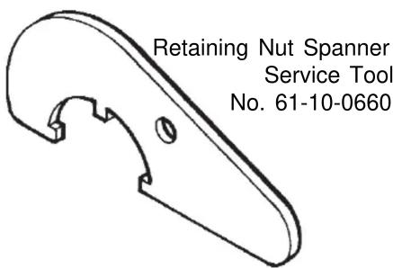
- insert & engage a 61-10-0660 retaining nut spanner with the notches in the 06-57-1050 clutch adjustment retaining nut.
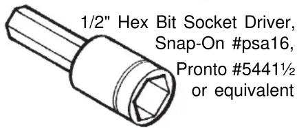
- with a 1/2" hex socket bit driver attached to a torque wrench, interlock the male hex with the female hex found in the threaded end of the dymo-drill spindle.
- turn the torque wrench clockwise ⬤, observing the torque reading and tighten the clutch adjustment retaining nut on the rear of the spindle shaft until a value of 25-30 ft-lbs is obtained.


Marke : MILWAUKEE
Modell : 4005
Kategorie : Nicht kategorisiert