
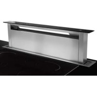
S-DDH3 - Dunstabzugshaube SIRIUS - Kostenlose Bedienungsanleitung
Finden Sie kostenlos die Bedienungsanleitung des Geräts S-DDH3 SIRIUS als PDF.


| Produkttyp | Induktionskochfeld mit integrierter Dunstabzugshaube |
| Modell | S-DDH3 |
| Marke | SIRIUS |
| Betriebsarten | Abluft (Außenabführung) und Umluft (mit Aktivkohlefilter) |
| Steuerung | Touch-Bedienung mit linearer Geschwindigkeitsregelung |
| Geschwindigkeitsstufen | 4 Stufen (Anzeige durch LEDs) |
| Timer-Funktion | Automatische Abschaltung nach 10 Minuten (einstellbar) |
| Automatische Abschaltung | Nach 4 Stunden Dauerbetrieb |
| Fettfilter-Sättigungsanzeige | Nach 30 Betriebsstunden (LEDs blinken); Reset über TIMER-Taste |
| Energieeffizienz | Konform mit EU-Richtlinien; Standby < 0,5 W |
| Elektrischer Anschluss | 220–240 V, 50/60 Hz; Absicherung: 10 A für Haube, 2x 20 A für Kochfelder |
| Gesamtleistung | 7.568 W (Kochfeld + Haube) |
| Mindestabstand zu Gasherden | 65 cm (Elektronikgehäuse) |
| Installationsöffnung (Unterschrank) | 410 mm x 410 mm |
| Maximale Abluftleitungslänge | 5 Meter; pro 90°-Bogen 1 Meter Abzug |
| Durchmesser Abluftleitung | 150 mm (konstant) |
| Reinigung Fettfilter | Spülmaschinenfest oder per Hand; alle 2 Monate |
| Wechsel Aktivkohlefilter | Alle 6 Monate (bei Umluftbetrieb) |
| Reinigung Gehäuse | Milde Reinigungsmittel und weiches Tuch; keine Scheuermittel |
| Sicherheitshinweise | Nicht für Gasherde; bei Glasbruch Gerät sofort ausschalten; Kinder fernhalten |
| Gewicht | Ca. 20 kg (geschätzt) |
Häufig gestellte Fragen - S-DDH3 SIRIUS
Benutzerfragen zu S-DDH3 SIRIUS
0 Frage zu diesem Gerät. Beantworten Sie die, die Sie kennen, oder stellen Sie Ihre eigene.
Eine neue Frage zu diesem Gerät stellen
Laden Sie die Anleitung für Ihr Dunstabzugshaube kostenlos im PDF-Format! Finden Sie Ihr Handbuch S-DDH3 - SIRIUS und nehmen Sie Ihr elektronisches Gerät wieder in die Hand. Auf dieser Seite sind alle Dokumente veröffentlicht, die für die Verwendung Ihres Geräts notwendig sind. S-DDH3 von der Marke SIRIUS.
BEDIENUNGSANLEITUNG S-DDH3 SIRIUS
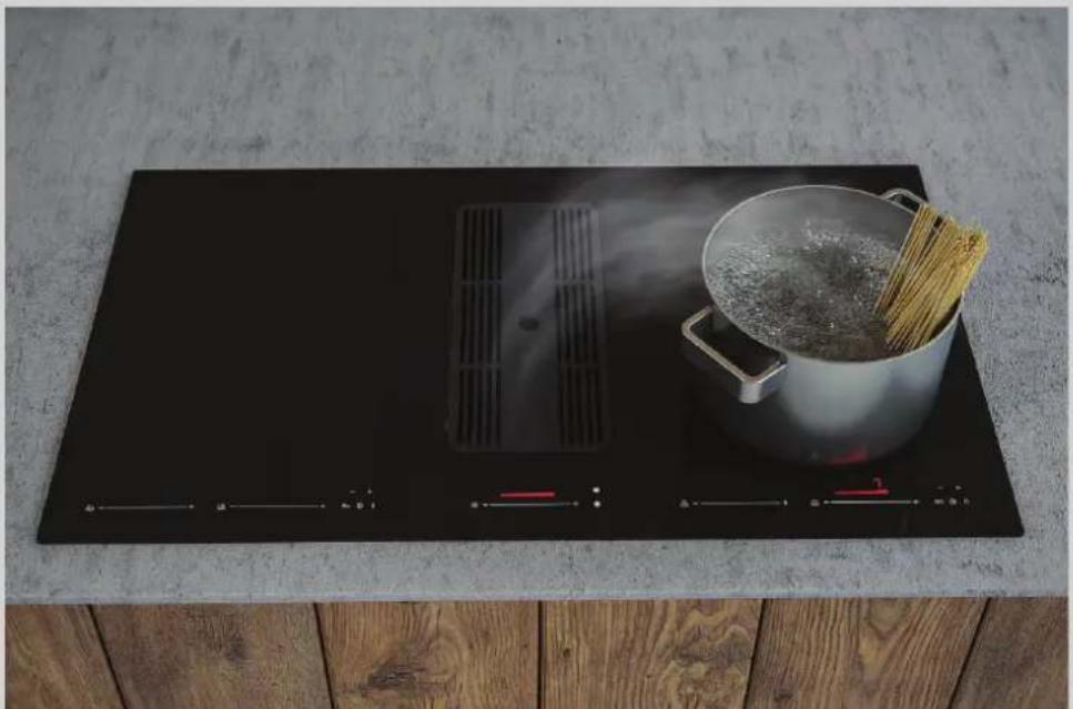
INTEGRATED INDUCTION HOB MODEL:
S-DDH3
ENERGY LABEL
natural_image
Top-down view of a black electric stove with a cooking pot and stirrer on top, placed on a wooden surface (no text or symbols visible)
natural_image
Symbol of a trash bin crossed out by two crossed lines, with a black horizontal bar below (no text or numbers present)The symbol on the product or on its packaging indicates that this product may not be treated as household waste. Instead it shall be handed over to the applicable collection point for the recycling of electrical and electronic equipment. By ensuring this product is disposed of correctly, you will help prevent potential negative consequences for the environment and human health, which could otherwise be caused by inappropriate waste handling of this product. For more detailed information about recycling of this product, please contact your local city office, your household waste disposal service or the shop where you purchased the product. This appliance is marked according to the European directive 2012/19/EC on waste electrical and electronic equipment (WEEE).
TO THE KIND ATTENTION OF THE USER
It is designed to work in both suctioning mode, with outside evacuation, and filtering mode.

WARNING

Keep these instructions for use with the appliance. If the appliance should be sold or passed on to others, make sure that the instructions are passed on with it. We thank you for taking note of these suggestions before installing and using the appliance. They have been written for your personal safety and the safety of others.
- This appliance is not intended for use by persons (including children) with reduced physical, sensory or mental capabilities, or lack of experience and knowledge, unless they have been given supervision or instruction concerning use of the appliance by a person responsible for their safety.
- CAUTION: Accessible parts may become hot when used with cooking appliances.
- Caution appliance is not to be used with gas hobs
- WARNING: If the surface is cracked, switch off the appliance to avoid the possibility of electric shock.
- Metallic objects such as knives, forks, spoons and lids should not be placed on the hob surface since they can get hot.
- After use, switch off the hob element by its control and do not rely on the pan detector.
- Danger of fire: Do not store items on the cooking surfaces.
- WARNING: Unattended cooking on a hob with fat or oil can be dangerous and may result in a fire.
SAFETY INSTRUCTIONS
These hoods have been designed for personal use in the home. The appliance must be used by adults. Make sure that the appliance is out of reach of children and that they do not use it to play with. Make sure that children do not operate the controls.
- When the appliance is delivered, check the overall appearance of the packaging.
Any remarks should be written on the delivery coupon, of which you keep a copy.
Your appliance is designed for normal domestic use. It is not designed for commercial or industrial use, or for purposes other than those for which it was designed.
- Any consequences of or damage from incorrect installation or incorrect use of the appliance will not be covered by the manufacturer's guarantee.
- Do not ever change or try to change the characteristics of this appliance. This would be a danger. Repairs must be performed only by an authorised technician.
Always disconnect the hood before carrying out cleaning or maintenance operations.
- Adequately ventilate the room when a cooker hood and other appliances, powered by energy other than electricity, are used simultaneously, so that the hood does not suck any combustion fumes.
- It is not allowed to cook food over open flames (flambé) or operate gas hobs without pots or pans on them under the hood itself (the flames sucked into the hood might damage the appliance).
- Frying under the appliance must be done under constant supervision as hot oils and fats may ignite. Respect the guidelines for cleaning and replacement of grease filters. Accumulated depo-sits of grease are a fire hazard.
- This appliance must not be used over cook tops powered by wood or coal or in any case, over cook tops with power levels that could damage the appliance.
Never use steam or high-pressure devices for cleaning your hood (regulations regarding electrical safety).
- Never use the cooker hood without the grease filters.
- The air must not be discharged into a flue for exhausting fumes from appliances burning gas or other fuels (not applicable to appliances that only discharge the air back into the room);
WARNING: Failure to install the screws or fixing device in accordance with these instructions may result in electrical hazards.
With the aim of constantly improving our products, we reserve to ourselves the right to update the product in its technical, functional or aesthetic features.
In case of external motor version, the normal operation of the hood works with an external ducting blower of the same manufacturer.
The exhausted air must not be conveyed in a channel used for appliances powered by energy other than electricity (heating systems etc.). To discharge the exhausted air please always respect regulations from competent authorities.
CONTENTS
DESCRIPTION OF THE APPLIANCE 5
HOW TO INSTALL THE APPLIANCE 6
ELECTRICAL CONNECTION OF THE APPLIANCE ....7
FUNCTIONS 8
CLEANING AND MAINTENANCE 9
DESCRIPTION OF THE APPLIANCE
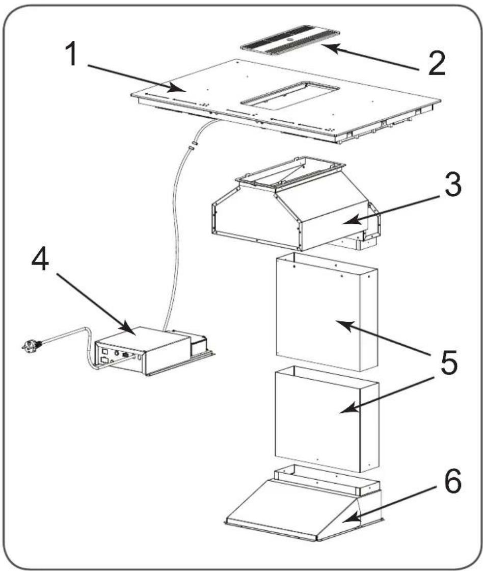
1 - INDUCTION HOB
2 - METAL GRID
3 - FILTERING CHAMBER
4 - WIRING BOX
5 - METAL CONDUIT
6 - METAL JOINT
HOW TO INSTALL COOKER HOOD
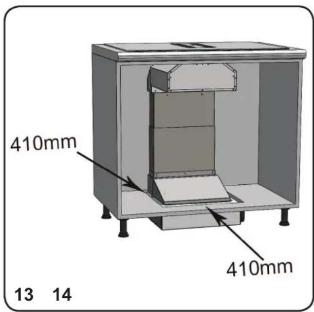
THE order to install the ventilation/fan unit in such a way as it can touch the floor, make a 410mm X 410mm opening in the cabinet bottom side (see fig.13).
-
Before carrying out the appliance installation, please check that all components are not damaged, in such a case contact your retailer and do not carry out any installation operation
-
Use an air exhausting duct whose maximum length does not exceed 5 meters
- Limit the number of elbows in the ducting, since each elbow reduces the air capacity of 1 linear meter. (Ex.: if you use no. 2 x 90° elbows, the length of piping should not exceed 3 meters).
- Avoid abrupt direction changes.
- Use a 150 mm. constant diameter or a similar section duct for the whole length.
-
Use a duct approved by relevant standards in force. The manufacturer shall not be held for air capacity or noise problems due to observance of aforementioned instructions and no warranty will be provided in such a case.
-
Place the upturned hob (PAG.13 PART. 1) on a suitable surface, making sure the glass is protected from scratches.
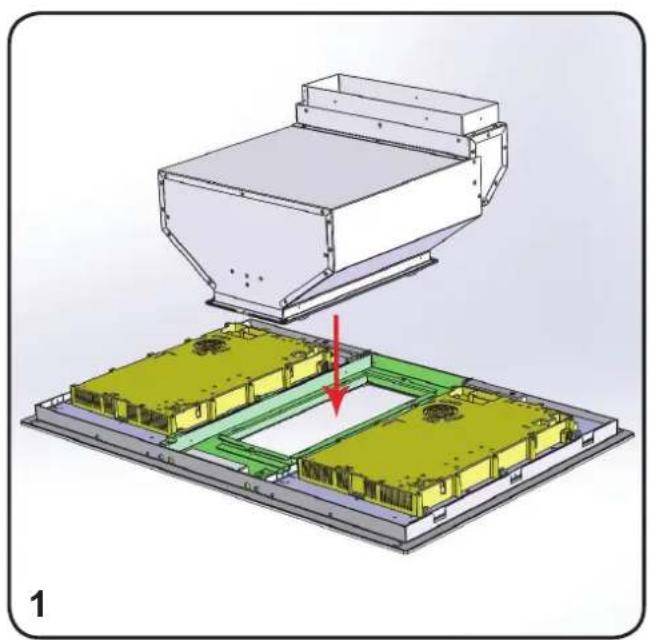
Take the ‘filtering chamber ‘out of the packaging and install it as shown in fig. 1.
The ‘filtering chamber’ metal hooks shall sorted in their suitable slots found or rear side, as shown in fig. 2.
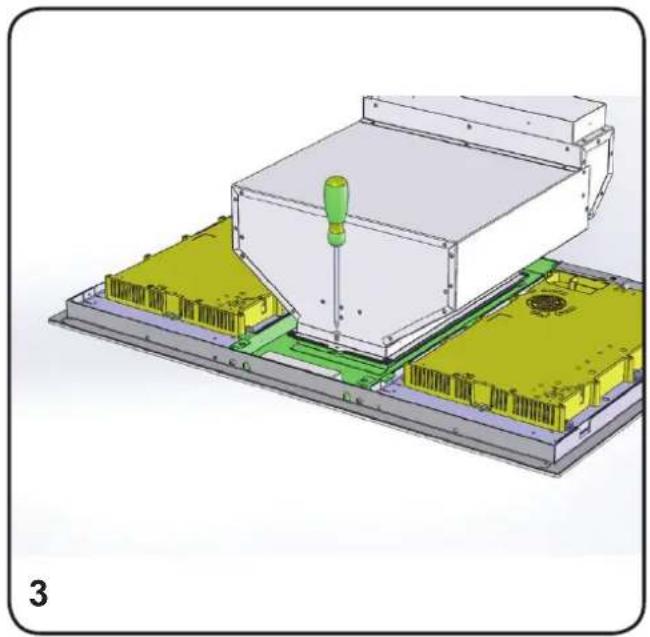
After fitting the ‘filtering chamber’ to the hob, fasten it using the metric screw provided with the appliance, which shall be installed as fig. 3.
Fit the hob into the cabinet, as shown in the related use instructions, included in the packing of the induction hob.
Take the ventilation/fan unit out of the packaging, fix the metal joint on it using the screws provided with the appliance, as shown in fig. 4.
After installing the hob, place the ventilation/fan unit immediately under the hob, as shown in fig. 5.
Then place the two metal telescopic conduits into the ventilation unit air inlet (figure 6), and fix them using the screws supplied with appliance.
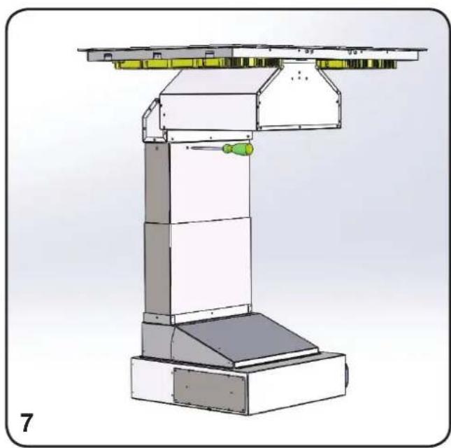
Lift the internal metal conduit until it reaches the 'filtering chamber' and fix it using the screws supplied with appliance (fig. 7).
Seal the air flow opening with the adhesive tape provided with the appliance, as shown in figure 8.
Connect the ducting to the ventilation unit. can use the air outlet on the right or left side of the ventilation unit, according to the needs of the kitchen: remove the four screws fixing the outlet flange and replace it with the metal lid placed on the opposite side.
The air outlet which is not going to be used must always be covered and closed with the metal lid. liable
due to non- plastic flanges are provided with the appliance to connect different section ducts.
Flanges provided have the following sections :
230x80 mm
220x90mm
218x55mm (recommended for filtering mode installation only).
ll be in the two grease filters into their housing on the hob passing them through the hob central openi see fig. 9.
Fit the metal grid in order to close the hob central opening, as shown in fig. 10. shown in
Place the wiring box near the appliance, in order to connect the flat cable to the corresponding flat cable of the touch - control panel.
Connect the ventilation/fan unit cable to the terminal block found inside the plastic black see fig. 11B.
ELECTRICAL CONNECTION OF THE PRODUCT

WARNING

Place the metal box containing the tronic components at a distance of no less than 65 cm from gas-operated cook tops or in any case, 65 cm from the suctioning surface of the cooker hood.

NOTE

We recommend installing the metal containing the electronic components at least 10 cm above floor level and at a suitable distance from all heat sources (e.g. sides or cook top).

CAUTION

This appliance is fitted with an H05 VVF 3 conductor, 0.75 mm2 (neutral, phase, and ground) power cord. This can be connected up to a 220 - 240 V mono-phase electrical network through CEI 60083 approved power socket, which must remain accessible after installation in compliance with installation regulations.
We decline any responsibility in case accidents caused by a lack of ground connection or incorrect ground connection. The appliance must be fed through a differential protection device (RCD), with nominal residual current not exceeding 30mA. If the power cord is damaged, call the after-sales service to avoid any risk.
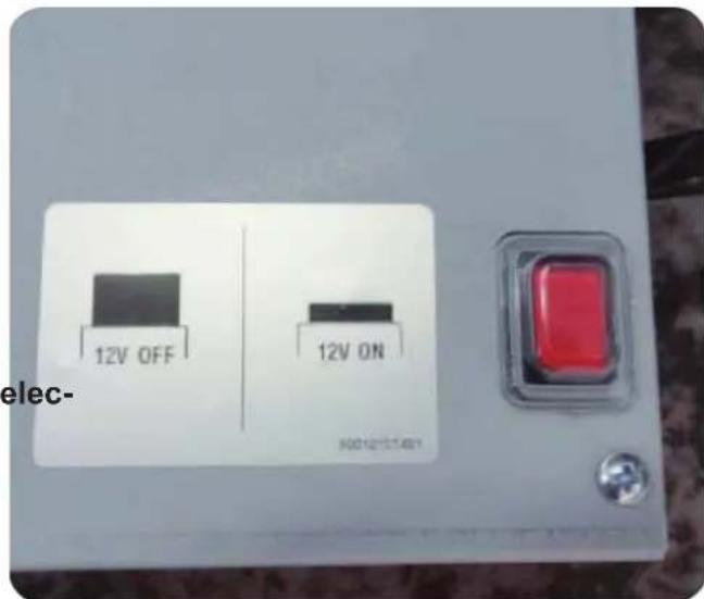
Once the installation is completed it is necessary to give electricity supply to the Down-sing the red button placed above the metallic box with the wiring boards inside.

WARNING

box Connecting the product to the mains electricity must be carried by technically qualified and specialised personnel. The product must be connected to an electrical system correctly designed and installed. The electrical system must comply with VDE0100 standard.

DANGER

If the product shows signs of a sconnect the appliance or remove the fuse corresponding to the disconnection line of the appliance.
If the product is not provided with a plug or if the plug is not easily accessible, it will be necessary to install a thermomagnetic circuit breaker switch on the electricity line between the product and the electrical system to which it is connected to that has a contact aperture of the poles of at least 3mm.
ELECTRICAL CONNECTION
The combined rating of extractor and hob is f7568Ws. Each side of the Induction hob is 3.7kw and requires a 20amp circuit for each or a 40amp for both.
The extractor can be connected to a 10amp GPO.
Filtering mode:
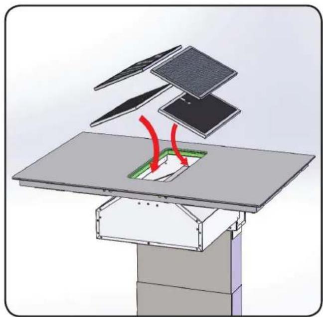
In case the appliance is used in the mode, charcoal filters are necessary which can be purchased as accessories and installed shown in fig. 12.
Charcoal filters are to be fit immediately under the grease filters, therefore you shall first fit the charcoal filters and then the grease filters.
Even in the case of filtering mode, you will need to provide a ducting allowing the air to go out of the cabinet. In order to prevent the formation of condensation, which can damage wooden or electrical parts.
FUNCTIONS
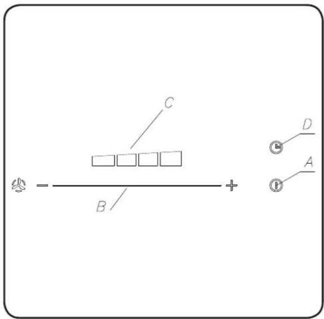
Touch control (fig. 14)
A: ON/OFF control. Allows to switch pliance on and to automatically set it ed. When the appliance is on at switches the fan off.
B: linear touch control. Allows to change the fan speed. It is possible to change the speed after the appliance is switched on acting on the ON/OFF key. Use the ON/OFF key to switch the fan off, as it is not possible to switch the fan off through this control.
C: Leds indicating the fan speed.
D: After 10 min from its setup, it allows to stop the motor.
The function you set is indicated by the flashing of "C" leds related to the set speed.
Automatic turn off:
After 4 hours of continuous working from the last setup, the appliance turns off automatically.
Grease filters saturation:
After 30 hours of operation, the speed indicators (fig. 14C) will all flash simultaneously, signaling the grease filters saturation.
To reset this function, press the “TIMER” key for at least 3 seconds, when the appliance is switched off.
TIMING
After result of the new EU65 “Energy label” and EU66 “Ecodesign” regulations issued by the Eu-asropean Commission, which came into force from January 1st, 2015, our products have been adapted to comply with these new requirements.
All of the models complying with the energy label the requirements, are equipped with new electronics including a timer device for suction speeds con- trol, when the air capacity exceeds 650m³/h. In- ternal motor models, with maximum air capacity higher than 650m³/h, are equipped with a of device that automatically switches the suction speed from 4th to 3rd speed, after 6 mi operation. External motor models are equippe with remote motors that, as for internal motor ver- sions, include a timer device that switches down the suction speed when it exceeds 650 m (See External Motors Instructions). Remote mo- tors, whose air capacity exceeds 650m³/h at both the ap default timer control functions: The suction spe is automatically switched from 4th to 2nd speed, after 6 minutes operation. If the appliance is wor- king at 3rd speed, it is automatically switched to 2nd speed, after 7 minutes operation. Operation speeds can still be changed during operatio The energy consumption of the appliance in stand - by mode is lower than 0.5W.
CLEANING AND MAINTENANCE
Careful maintenance ensures proper operation and good performances over time.
Grease filters can be washed by hand or in the dishwasher.
Grease filters shall be cleaned depending on use, at least once every two months.
The charcoal filter shall be replaced depending on use,, at least once every six months.
The power cord replacement shall be performed by authorized personnel only.
Use only tepid water and neutral detergents to clean the appliance; the use of products containing abrasive substances shall be avoided.
IMAGES
IT
natural_image
3D diagram of a device with a conical component above a grid base, showing internal components and a red arrow indicating motion (no text or symbols present)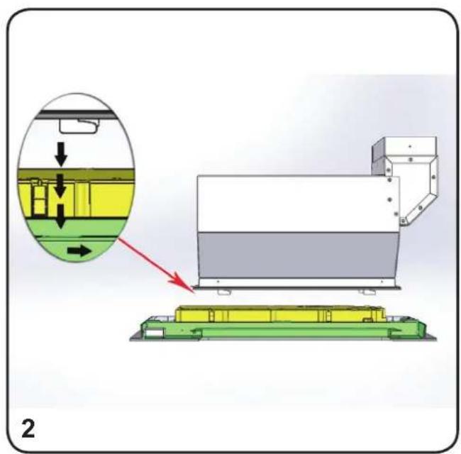
natural_image
3D mechanical assembly diagram showing a housing with a green screwdriver inserted, mounted on a base platform (no text or symbols visible)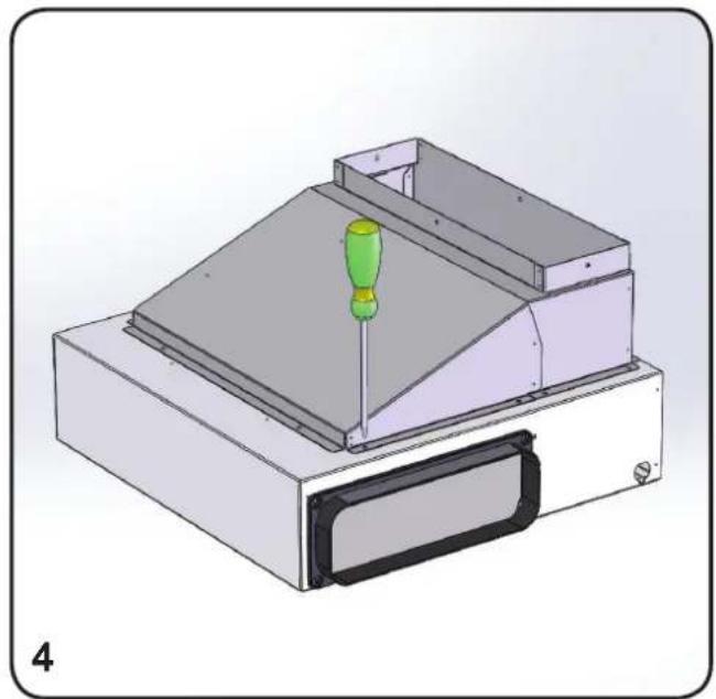
natural_image
3D mechanical assembly diagram showing a green screwdriver inserted into a layered component (no text or symbols visible)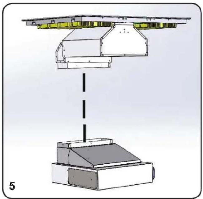
natural_image
Technical diagram of a mechanical assembly with a vertical dashed line and labeled component '5' (no text or symbols on the diagram itself)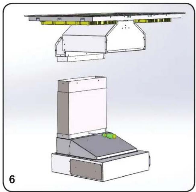
natural_image
Technical illustration of a mechanical assembly with two views: top shows a structural frame, bottom shows a base platform (no text or symbols)IT
natural_image
Technical diagram of a mechanical device with layered components and a green handle (no text or symbols)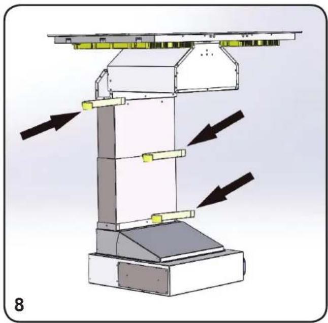
natural_image
Technical diagram of a mechanical device with directional arrows indicating flow or movement (no text or symbols present)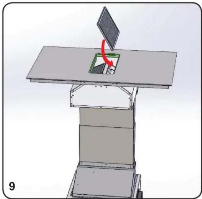
natural_image
3D diagram of a mechanical assembly with a green component and red directional arrow, no visible text or symbols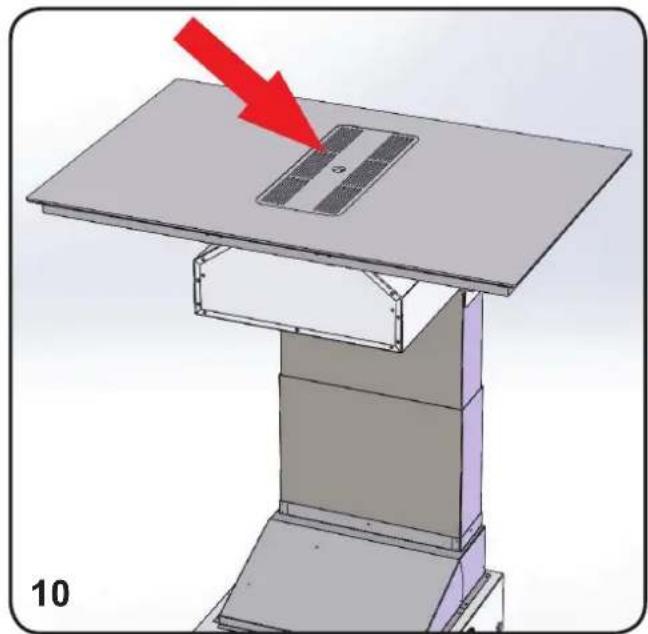
natural_image
3D diagram of a mechanical device with a red arrow pointing to a component on top, labeled '10' (no text or symbols on the device itself)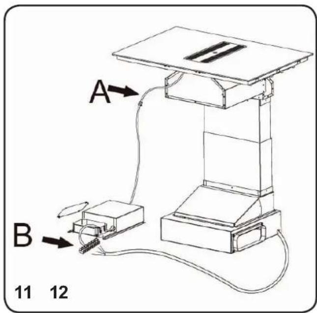
natural_image
3D diagram of a solar panel assembly with layered components and red directional arrows indicating motion (no text or symbols)IT

bar
| Category | Value | |---|---| | 90002020003 - 09/17 | 90002020003 - 09/17 |
- S-DDH3
- TO THE KIND ATTENTION OF THE USER
- WARNING
- SAFETY INSTRUCTIONS
- WARNING: Failure to install the screws or fixing device in accordance with these instructions may result in electrical hazards.
- CONTENTS
- DESCRIPTION OF THE APPLIANCE
- HOW TO INSTALL COOKER HOOD
- ELECTRICAL CONNECTION OF THE PRODUCT
- NOTE
- CAUTION
- DANGER
- ELECTRICAL CONNECTION
- Filtering mode:
- FUNCTIONS
- Automatic turn off:
- Grease filters saturation:
- TIMING
- CLEANING AND MAINTENANCE
- IMAGES
Marke : SIRIUS
Modell : S-DDH3
Kategorie : Dunstabzugshaube