
700HTP-2 - Pumpe FLUKE - Kostenlose Bedienungsanleitung
Finden Sie kostenlos die Bedienungsanleitung des Geräts 700HTP-2 FLUKE als PDF.


| Produkttyp | Hydraulische Testpumpe |
| Marke | Fluke |
| Modell | 700HTP-2 |
| Maximaler Druck | 10.000 psi (690 bar) |
| Hydraulikmedium | Destilliertes Wasser, mineralisches Hydrauliköl oder Hydrauliköl bis 100 (30 W) |
| Nassmaterialien | 303 Edelstahl, Aluminium, Polyurethan, PTFE, Nitril und Nylon |
| Gewicht | 1,29 lb (0,58 kg) |
| Abmessungen (L x B x H) | 9,5 x 6,1 x 2,6 Zoll (241 x 155 x 66 mm) |
| Anschlüsse | 1/4 Zoll NPT weiblich (Master- und Testdruckanschluss), 1/4 Zoll NPT T-Stück |
| Feineinstellung | Vernier-Feineinstellknopf für kleine Druckänderungen |
| Druckablass | Druckablassknopf zur langsamen Druckentlastung |
| Handgriffbegrenzer | Begrenzt den Hub der Griffe für leichteres Pumpen bei hohem Druck |
| Lieferumfang | Pumpe mit T-Stück, zwei 1/4" NPT auf 1/4" BSP Adapter, ein 1/4" NPT auf 1/4" NPT und ein 1/4" NPT auf 1/8" NPT Adapter, Anleitung |
| Wartung | Regelmäßiges Reinigen des Reservoirs; Ersatzteile: Rebuild Kit (PN 4097836), Hydraulikreservoir-Kit (PN 2844341), Griff-Kit (PN 2844352) |
| Sicherheitshinweise | Druckablassknopf langsam öffnen; nicht an externe Druckquelle anschließen; Überdruckschutz verwenden |
| Garantie | 1 Jahr auf Material- und Verarbeitungsfehler |
Häufig gestellte Fragen - 700HTP-2 FLUKE
Benutzerfragen zu 700HTP-2 FLUKE
0 Frage zu diesem Gerät. Beantworten Sie die, die Sie kennen, oder stellen Sie Ihre eigene.
Eine neue Frage zu diesem Gerät stellen
Laden Sie die Anleitung für Ihr Pumpe kostenlos im PDF-Format! Finden Sie Ihr Handbuch 700HTP-2 - FLUKE und nehmen Sie Ihr elektronisches Gerät wieder in die Hand. Auf dieser Seite sind alle Dokumente veröffentlicht, die für die Verwendung Ihres Geräts notwendig sind. 700HTP-2 von der Marke FLUKE.
BEDIENUNGSANLEITUNG 700HTP-2 FLUKE
How to Prime the Test Pump
Before you connect the Pump to the Unit Under Test (UUT), the Pump must be filled with fluid and primed for use. Follow the directions below to prepare the Pump for use.
- Fill the Pump with fluid:
a. Remove the Reservoir Filler Cap (item ⑧.)
b. Fill the Hydraulic Fluid Reservoir approximately two-thirds full (66 cc) with distilled water, mineral oil, or hydraulic oil.
Note
If water is used in the Pump, use only DISTILLED water and drain the water out of the Pump after use.
c. Install the Reservoir Filler Cap (item ⑧.) Tighten by hand.
- Prime the Pump:
a. Adjust the Vernier Fine Adjustment Knob (item ④) to the approximate middle-range.
b. Turn the Pressure Bleed Knob (item ⑨) clockwise until it stops in the full closed position.
c. Squeeze the handles together to pump fluid. Pump fluid until fluid shows at the Pump Port.
d. Attach the fluid hose to the Pump.
e. Squeeze the handles together until fluid shows at the end of the hose.
f. Attach the fluid hose to the Unit Under Test (UUT) and squeeze the Pump handles until pressure increases.
g. Bleed the trapped air from the Pump. Pressurize the Pump to 1,000 psi then slowly turn the Pressure Bleed Knob (item ⑨) counter-clockwise to release pressure.
Notes
- As the pressure rises it will be hard to squeeze the handles together. Use the Handle Limiter (item ⑦) to limit the travel of the handles which will make them easier to squeeze together. To toggle the Handle Limiter on or off, squeeze the handles together and push the Handle Limiter (item ⑦) in or out.
- The rate at which the pressure increases is directly related to the test configuration (hose length and volume of UUT.)
Replacement Parts
Rebuild Kit, Fluke PN 4097836
Hydraulic Fluid Reservoir Rebuild Kit, Fluke PN 2844341
Handle Assembly Rebuild Kit, Fluke PN 2844352
LIMITED WARRANTY AND LIMITATION OF LIABILITY
This Fluke product will be free from defects in material and workmanship for one year from the date of purchase. This warranty does not cover fuses, disposable batteries, or damage from accident, neglect, misuse, alteration, contamination, or abnormal conditions of operation or handling. Resellers are not authorized to extend any other warranty on Fluke's behalf. To obtain service during the warranty period, contact your nearest Fluke authorized service center to obtain return authorization information, then send the product to that Service Center with a description of the problem.
THIS WARRANTY IS YOUR ONLY REMEDY. NO OTHER WARRANTIES, SUCH AS FITNESS FOR A PARTICULAR PURPOSE, ARE EXPRESSED OR IMPLIED. FLUKE IS NOT LIABLE FOR ANY SPECIAL, INDIRECT, INCIDENTAL OR CONSEQUENTIAL DAMAGES OR LOSSES, ARISING FROM ANY CAUSE OR THEORY. Since some states or countries do not allow the exclusion or limitation of an implied warranty or of incidental or consequential damages, this limitation of liability may not apply to you.
Fluke Corporation
Fluke Europe B.V
P.O. Box 9090
P.O. Box 1186
Everett, WA 98206-9090
5602 BD Eindhoven
U.S.A.
The Netherlands
Fluke-700HTP-2
Hydraulic Test Pump
Instruction Sheet
Introduction
The Fluke 700HTP-2 Hydraulic Test Pump (the Pump or Product) is a portable source of high pressure.
Safety
Warning
To prevent personal injury, use the Product only as specified, or the protection supplied by the Product can be compromised.
Pump Specifications
• Maximum pressure: 10,000 psi (690 bar)
- Hydraulic media: distilled water, mineral based hydraulic oil, or up to hydraulic oil 100 (30 W).
- Wetted materials: 303 stainless steel, aluminum, polyurethane, PTFE, nitrile, and nylon.
• Weight: 1.29 lb (0.58 kg)
- Dimensions: length 9.5 in (241 mm), width 6.1 in (155 mm), depth 2.6 in (66 mm)
Box Contents
- Model 700HTP-2 Hydraulic Test Pump with a 1/4-inch NPT tee installed.
- Two 1/4-inch NPT male to 1/4-inch BSP female adapters.
• One 1/4-inch NPT male to 1/4-inch NPT male fitting.
• One 1/4-inch NPT male to 1/8-inch NPT male fitting. - Instruction Sheet
How to Contact Fluke
To contact Fluke, call one of the following telephone numbers:
- Technical Support USA: 1-800-44-FLUKE (1-800-443-5853)
- Calibration/Repair USA: 1-888-99-FLUKE (1-888-993-5853)
• Canada: 1-800-36-FLUKE (1-800-363-5853)
• Europe: +31 402-675-200
• Japan: +81-3-6714-3114
• Singapore: +65-738-5655
• Anywhere in the world: +1-425-446-5500
Or, visit Fluke's website at www.fluke.com.
To register your product, visit http://register.fluke.com.
To view, print, or download the latest manual supplement, visit http://us.fluke.com/usen/support/manuals.
PN 4096896
September 2011
©2011 Fluke Corporation. All rights reserved. Printed in U.S.A.
All product names are trademarks of their respective companies.
Features
| gsp001.eps | ||
| No. | Item Function | |
| ① | Master Instrument Port | Port for Fluke 700 Series Pressure Module, 1/4-inch NPT female. |
| ② | Test Pressure Port | Port for pressure instrument under test, 1/4-inch NPT female. |
| ③ | Pressure Relief Valve Port | Port for an optional Fluke 700PRV-1 Pressure Relief Valve (plugged). |
| ④ | Vernier Fine Adjustment Knob | Lets you adjust the applied pressure in small increments. |
| ⑤ | Hydraulic Fluid Reservoir | Holds 100 cc of mineral based hydraulic oil, distilled water, or hydraulic oil. |
| ⑥ | 1/4-inch NPT Tee Fitting | For master and test ports. |
| ⑦ | Handle Limiter Limits | the travel of the handles. |
| ⑧ | Reservoir Filler Cap | Cap which seals the hydraulic fluid reservoir. Install before you pump. |
| ⑨ | Pressure Bleed Knob | Lets you release pressure in small increments. |
| ⑩ | Reservoir Nut Remove nut to clean reservoir. | |
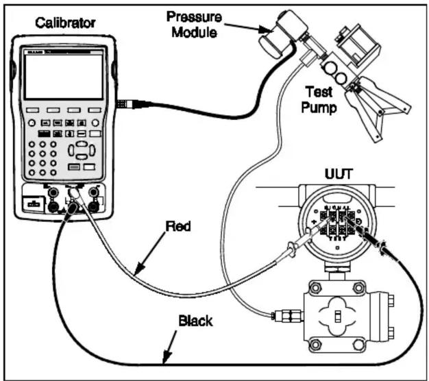
Figure 1. Test Configuration
gsp002.eps
How to Operate the Test Pump
⚠ Warning
To prevent a violent release of pressure, open the Pressure Bleed Knob (item ⑨) very slowly before you disconnect pressure lines. Do not connect the Pump to an external pressure source.
Caution
To prevent damage when a Pressure Module or Pressure Instrument is connected that could be damaged by pressures of 690 bar (10,000 psi), install and correctly set a relief valve in the system or an optional Fluke 700PRV-1 Pressure Relief Valve on the Pump.
- Connect a 700 Series Pressure Module (the Pressure Module) to the Master Instrument Port (item ①.) To connect to a 700P High Pressure Module (700P29, P30, or P31) install a male 1/4-inch NPT Adapter. Use Teflon® tape or equivalent on the NPT thread connections to prevent leaks.
- Fill and Prime the Pump. See "How to Prime the Test Pump".
- Connect the Pressure Module to the calibrator as shown in Figure 1.
- Connect the input of the Pressure Unit Under Test (UUT) to the Test Pressure Port (item ②) on the Test Pump.
- Loosen the Pressure Bleed Knob (item ⑨) to release pressure from the Pump.
- Use the Calibrator to zero the Pressure Module. Refer to the Users Manual for instructions.
- Turn the Vernier Fine Adjustment Knob (item ④) to the middle-range.
- Turn the Pressure Bleed Knob (item ⑨) clockwise until it stops in the full closed position.
- Squeeze the handles together to pump fluid which will increase pressure. See the Notes in step 2 of the "How to Prime the Test Pump" procedure.
Caution
To prevent damage, do not let the pressure increase to more than the pressure rating of the equipment under test. Pressure can increase quickly if the pressurized volume is small.
-
For incremental pressure adjustments, use the Vernier Fine Adjustment Knob.
-
Once the test is done, slowly turn the Pressure Bleed Knob (item ⑨) counter-clockwise to release pressure.
Marke : FLUKE
Modell : 700HTP-2
Kategorie : Pumpe