
48-22-8436 - Nicht kategorisiert MILWAUKEE - Kostenlose Bedienungsanleitung
Finden Sie kostenlos die Bedienungsanleitung des Geräts 48-22-8436 MILWAUKEE als PDF.


| Produkttyp | PACKOUT S-Organizer Compact Assembly |
| Marke | Milwaukee |
| Modell | 48-22-8436 |
| Farbe | Rot / Schwarz |
| Material | Polypropylen (hochschlagfest) |
| Systemkompatibilität | PACKOUT-Modulsystem – vollständig stapelbar und verriegelbar |
| Anzahl der Fächer | 5 herausnehmbare Einsätze mit Trennwänden (6 Trennwände im Lieferumfang) |
| Verschluss | 2 Schnappverschlüsse (LP Compact Org Latch) |
| Deckeldichtung | Ja, aus Gummi – schützt vor Feuchtigkeit und Staub |
| Tragbar | Ja, mit integriertem Seitengriff (separat erhältlich) |
| Reinigung | Mit milder Seifenlauge und weichem Tuch reinigen. Keine aggressiven Lösungsmittel verwenden. |
| Wartung | Verschlüsse und Dichtungen regelmäßig auf Beschädigungen prüfen |
| Ersatzteile | Verschluss-Set (44-20-8436), Dichtung (43-44-8435), 5er-Bin-Einsatz (31-01-0502), Trennwand-Kit (31-01-0503) |
| Anwendungsbereich | Werkstatt, Baustelle, Heimwerker – Aufbewahrung von Kleinmaterial und Zubehör |
| Lieferumfang | 1 Basis-Organizer, 1 Deckel mit Dichtung, 2 Verschlüsse, 1 herausnehmbarer 5-Fach-Einsatz mit 6 Trennwänden |
Häufig gestellte Fragen - 48-22-8436 MILWAUKEE
Benutzerfragen zu 48-22-8436 MILWAUKEE
0 Frage zu diesem Gerät. Beantworten Sie die, die Sie kennen, oder stellen Sie Ihre eigene.
Eine neue Frage zu diesem Gerät stellen
Laden Sie die Anleitung für Ihr Nicht kategorisiert kostenlos im PDF-Format! Finden Sie Ihr Handbuch 48-22-8436 - MILWAUKEE und nehmen Sie Ihr elektronisches Gerät wieder in die Hand. Auf dieser Seite sind alle Dokumente veröffentlicht, die für die Verwendung Ihres Geräts notwendig sind. 48-22-8436 von der Marke MILWAUKEE.
BEDIENUNGSANLEITUNG 48-22-8436 MILWAUKEE
| SPECIFY CATALOG NO. AND SERIAL NO. WHEN ORDERING PARTS | REVISED BULLETIN | DATEOct. 2020 | |
| PACKOUTTM Rolling Tool Box Assembly | |||
| CATALOG NO. 48-22-8426 | SERIALNUMBER | WIRING INSTRUCTION | |
48-22-8426 Includes:
| 48-22-8425 | PACKOUTTM Large Tool Box Assembly | Page 3 |
| 48-22-8424 | PACKOUTTM Medium Tool Box Assembly | Page 3 |
| 48-22-8430 | PACKOUTTM Organizer Assembly | Page 4 |
| 48-22-8435 | PACKOUTTM Compact Organizer Assembly | Page 4 |
| 48-22-8310 | PACKOUTTM Small 10" Storage Tote | Page 5 |
| 48-22-8315 | PACKOUTTM Medium 15" Storage Tote | Page 5 |
| 48-22-8320 | PACKOUTTM Large 20" Storage Tote | Page 5 |
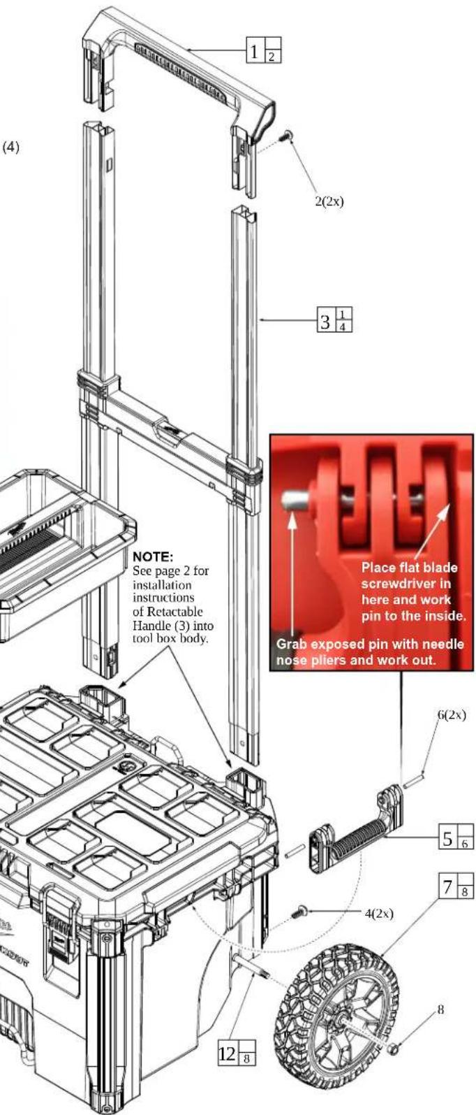
FIG. PART NO. DESCRIPTION OF PART NO. REQ.
| 1 43-62-8400T Retractable Handle Grip Service Kit (1) | |||
| 2 | ---- | Screw (2) | |
| 3 | 43-62-8400 | Retractable Handle Service Assembly | (1) |
| 4 | ---- | Screw (2) | |
| 5 | 43-62-8426 | Side Handle Svc. Kit (Contains 2 Side Handles and 4 Pins) (1) | |
| 6 | ---- | Pin | (4) |
| 7 | 45-94-8426 | Wheel Svc. Kit (Contains 2 Wheels and 2 Locking Hex Nuts) (1) | |
| 8 | ---- | Locking Hex Nut | (2) |
| 9 | 44-20-8400 | Latch Service Assembly (Set of 2) | (1) |
| 10 | 31-01-8400 | Storage Tray | (1) |
| 11 | 43-44-8400 | Lid Gasket (Not Shown) | (1) |
| 12 | 42-12-8426 | Axle Svc. Kit (Contains 1 Axle and 2 Locking Hex Nuts) | (1) |
*See page 6 thru 13 for Additional Storage Products:
| 48-22-8431 | PACKOUTTM S-Organizer Assembly | Page 6 |
| 48-22-8436 | PACKOUTTM S-Organizer Compact Assy. | Page 6 |
| 48-22-8450 | PACKOUTTM Tool Box Assembly | Page 7 |
| 48-22-8321 | PACKOUTTM Medium 15" Tool Bag | Page 8 |
| 48-22-8322 | PACKOUTTM Large 20" Tool Bag | Page 8 |
| 48-22-8300 | PACKOUTTM Tech Bag | Page 9 |
| 48-22-8301 | PACKOUTTM Jobsite Backpack | Page 9 |
| 48-22-8302 | PACKOUTTM Jobsite Cooler | Page 9 |
| 48-22-8410 | PACKOUTTM Flat Dolly | Page 10 |
| 48-22-8422 | PACKOUTTM Compact Toolbox | Page 11 |
| 48-22-8460 | PACKOUTTM Compact Cooler | Page 11 |
| 48-22-8488 | PACKOUTTM Customizable Work Surface | Page 12 |
| 48-22-8415 | PACKOUTTM 2 Wheeled Dolly Page 13 |
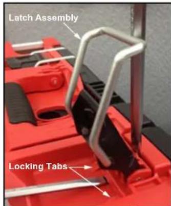
As an aid to removing a damaged Latch Assembly (9), use two large flat blade screwdrivers. Push blades between parts as shown. Twist both screwdrivers at same time to force the blades into opening and work the latch assembly over the two locking tabs.
To install a new latch assembly, position entire latch assembly over locking tabs with the two top lugs partially inserted in 'catch cavity' of main housing. Engage latch bar onto lid and gently press latch lever to slide assembly over two locking tabs and into place.
This removal and installation process will be the same where other service latches are offered in this system.
MILWAUKEE TOOL • www.milwaukeetool.com
13135 W. LISBON RD., BROOKFIELD, WI 53005
Drwg. 7

EXAMPLE:
Component Parts (Small #) Are Included When Ordering The Assembly (Large #).
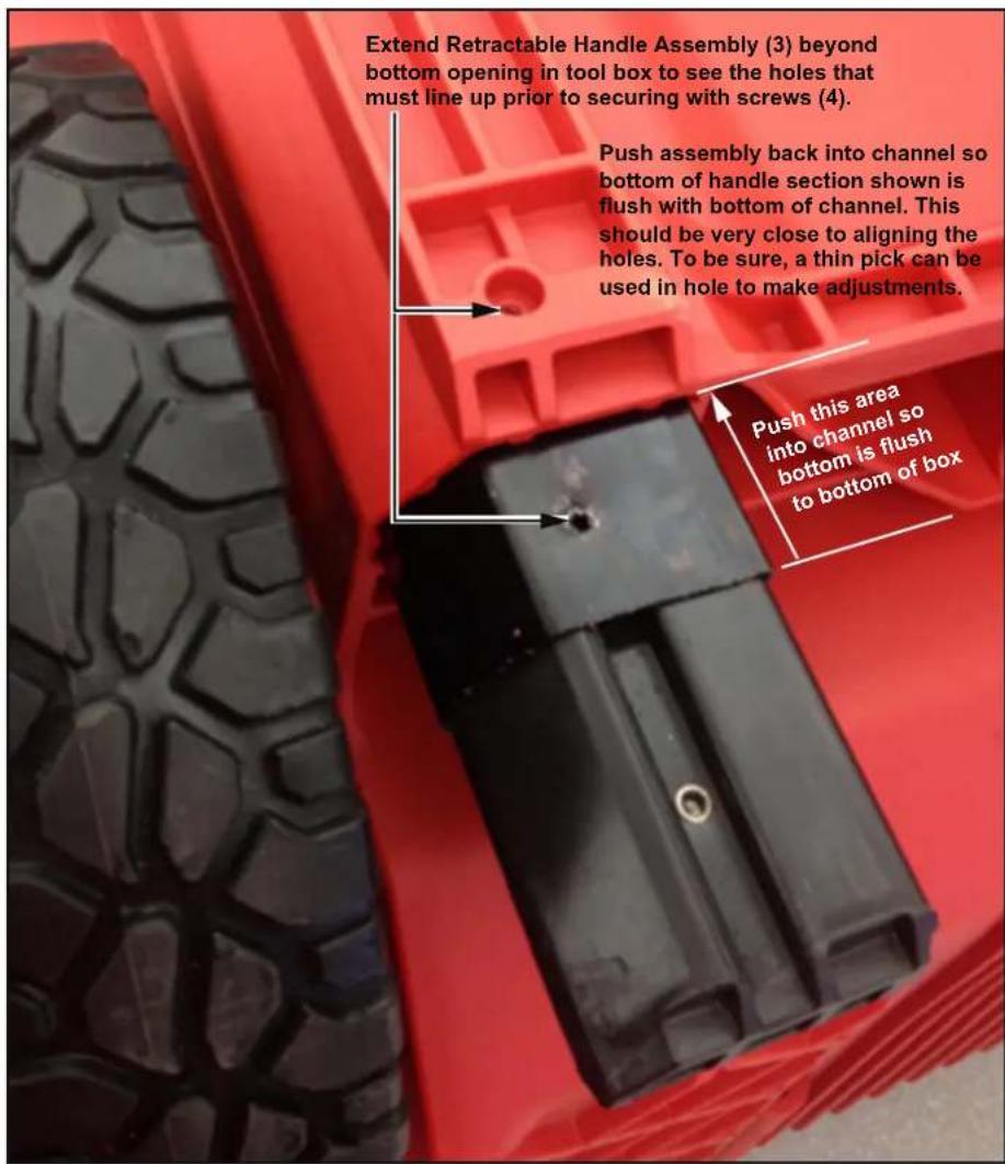
As an aid to installation, collapse the Retractable Handle Assembly (3).
Properly orient the assembly and insert both sides into tool box channels.
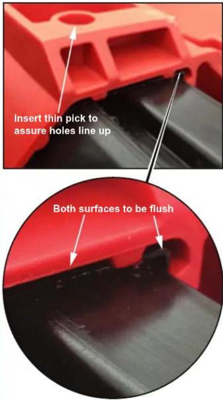
Holes of Retractable Handle Assembly (3) must line up with holes on the back of tool box body prior to securing with screws (4).
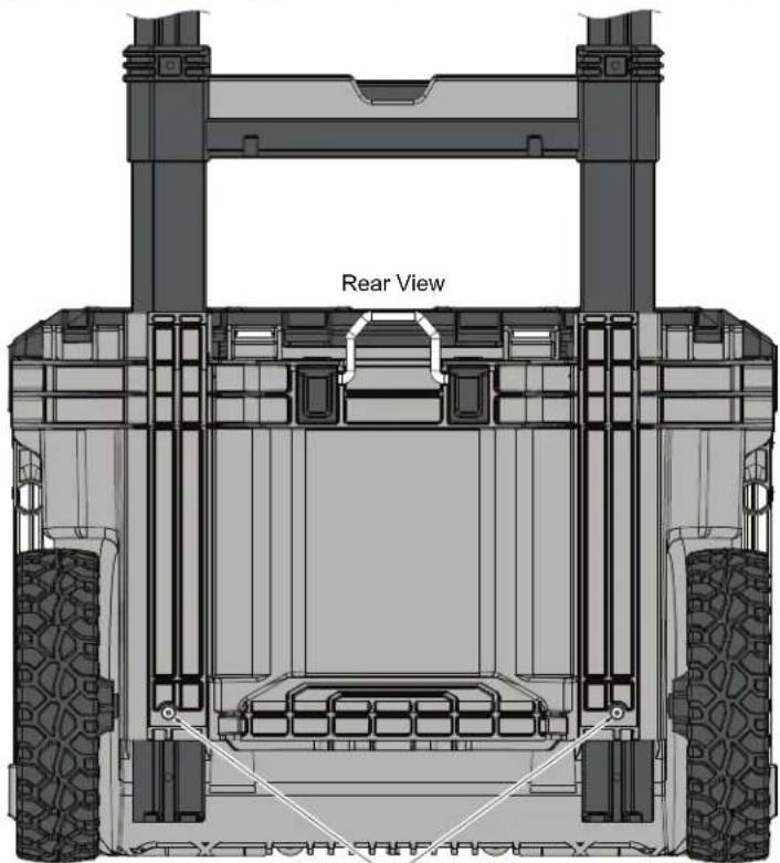
Screws (4)
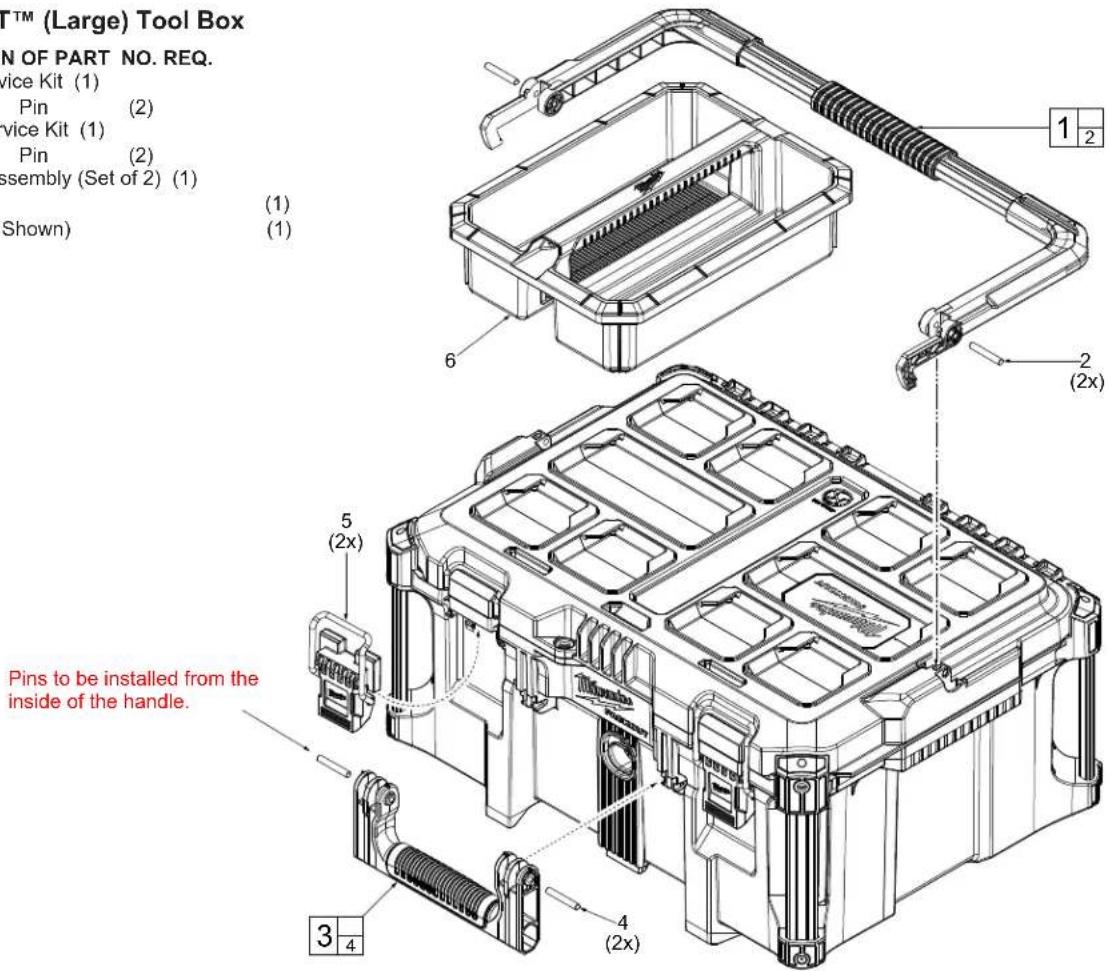
48-22-8425 PACKOUT™ (Large) Tool Box
FIG. PART NO. DESCRIPTION OF PART NO. REQ.
1 43-62-8425 Top Handle Service Kit (1)
2 Pin (2)
3 43-62-8424 Side Handle Service Kit (1)
4 Pin (2)
5 44-20-8400 Latch Service Assembly (Set of 2) (1)
6 31-01-8400 Storage Tray (1)
7 43-44-8400 Lid Gasket (Not Shown) (1)
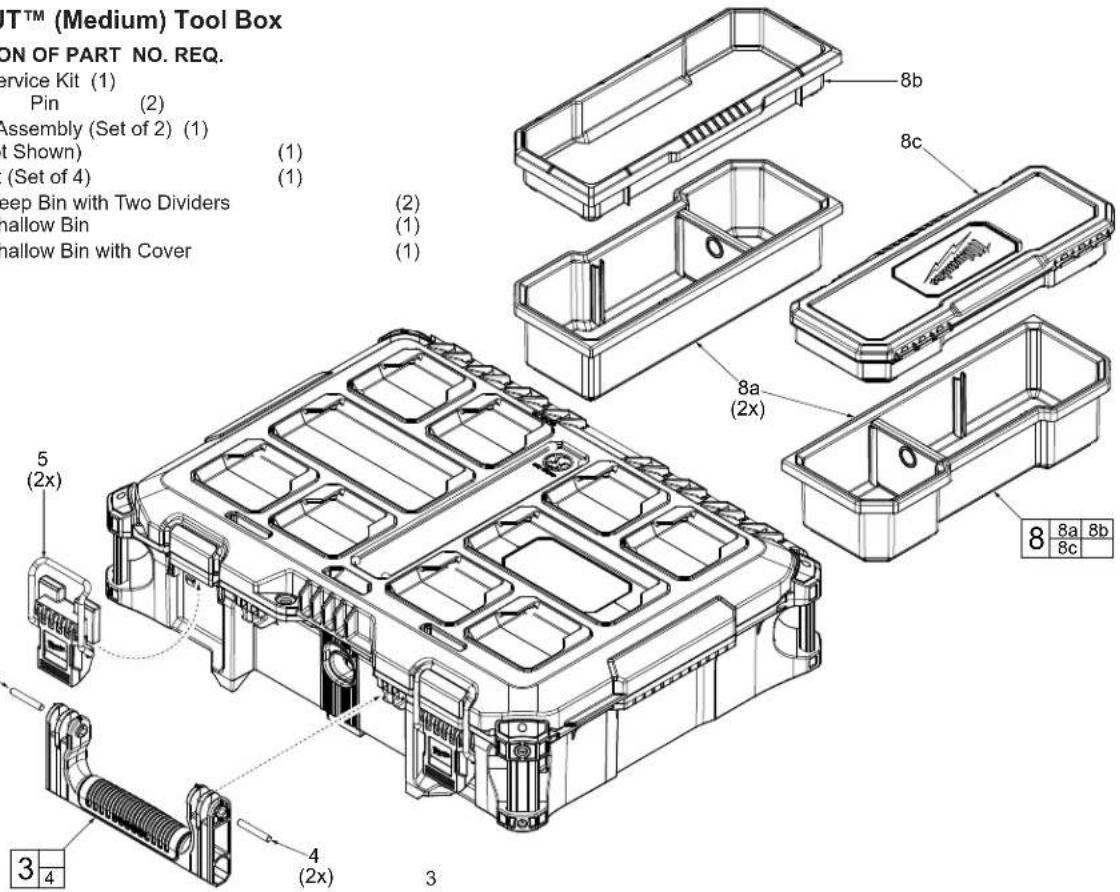
48-22-8424 PACKOUT™ (Medium) Tool Box
FIG. PART NO. DESCRIPTION OF PART NO. REQ.
3 43-62-8424 Side Handle Service Kit (1)
4 Pin (2)
5 44-20-8400 Latch Service Assembly (Set of 2) (1)
7 43-44-8400 Lid Gasket (Not Shown) (1)
8 31-01-8424 Storage Bin Kit (Set of 4) (1)
8a Deep Bin with Two Dividers (2)
8b ---- Shallow Bin (1)
8c ---- Shallow Bin with Cover (1)
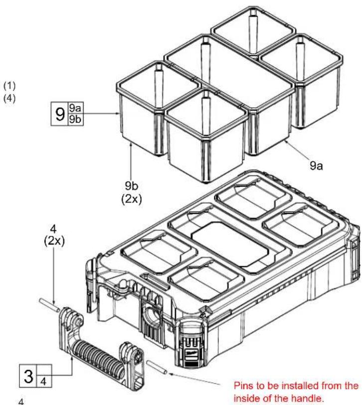
Pins to be installed from the inside of the handle.
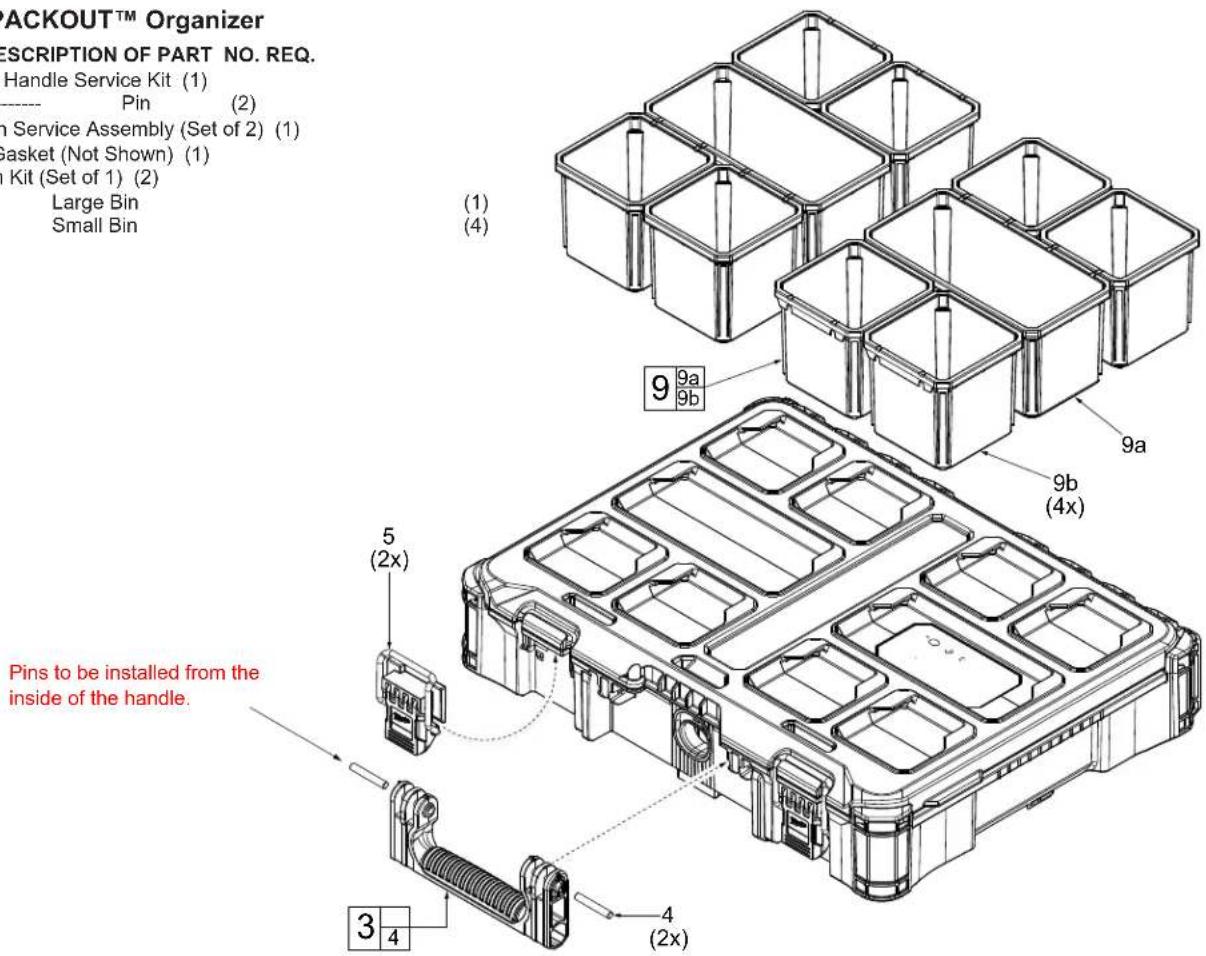
48-22-8430 PACKOUT™ Organizer
FIG. PART NO. DESCRIPTION OF PART NO. REQ.
3 43-62-8430 Side Handle Service Kit (1)
4 Pin (2)
5 44-20-8430 Latch Service Assembly (Set of 2) (1)
7 43-44-8430 Lid Gasket (Not Shown) (1)
9 31-01-0501 5 Bin Kit (Set of 1) (2)
9a Large Bin
9b Small Bin
48-22-8435 PACKOUT™ Compact Organizer
FIG. PART NO. DESCRIPTION OF PART NO. REQ.
3 43-62-8435 Side Handle Service Kit (1)
4 Pin (2)
7 43-44-8435 Lid Gasket (Not Shown) (1)
9 31-01-0501 5 Bin Kit (1)
9a Large Bin
9b Small Bin
48-22-8310 10" PACKOUT™(Small) Storage Tote 48-22-8315 15" PACKOUT™ (Medium) Storage Tote 48-22-8320 20" PACKOUT™ (Large) Storage Tote
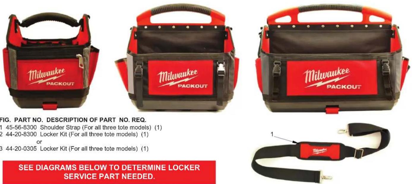
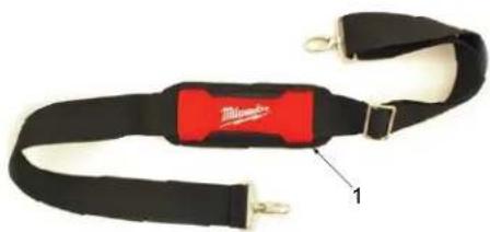
1 45-56-8300 Shoulder Strap (For all three tote models) (1)
2 44-20-8300 Locker Kit (For all three tote models) (1)
or
3 44-20-0305 Locker Kit (For all three tote models) (1)
natural_image
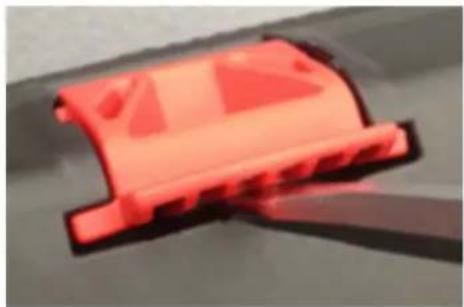
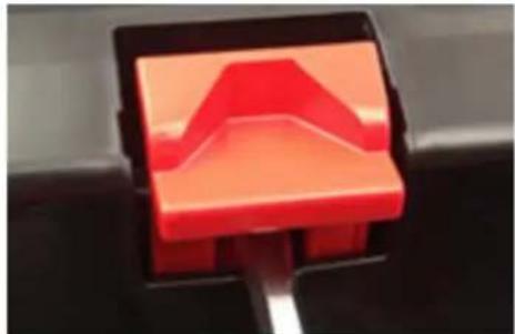
Close-up of a red, glowing object resembling a mechanical component or tool (no visible text or symbols)To remove a damaged locker system, flip tote upside down and approach tote from the bottom of base. Insert a large flat blade screwdriver in middle of locking carriage as shown. Lightly pry carriage upward out of base opening. Remove and discard old locking carriage and spring.
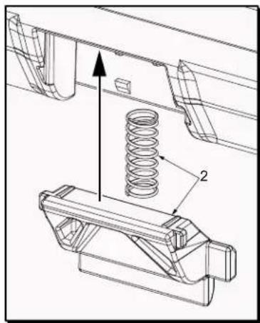
No. 44-20-8300
Locker Kit
For early production PACKOUT™
Storage Totes
To install a Locker Kit (2), align spring as shown and guide the tabs of locking carriage in channels of tote base. Push locking carriage upward to snap into place.
natural_image
Close-up of a red abstract geometric object mounted on a black stand (no text or symbols visible)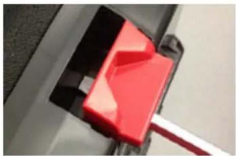
natural_image
Close-up of a red 3D cube being inserted into a black plastic component (no text or symbols visible)To remove a damaged locker system, flip tote over on the side and approach tote from the bottom of base. Insert a large flat blade screwdriver in middle of locking carriage as shown. Lightly pry carriage upward out of base opening. Remove and discard old locking carriage.
natural_image
Technical line drawing of a mechanical assembly with no visible text or symbolsNo. 44-20-0305
Locker
For later production PACKOUT™
Storage Totes
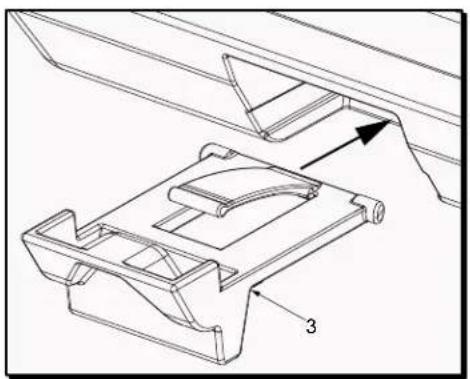
To install a new Locker (3), guide the tabs of locking carriage in channels of tote base. Push locking carriage forward to snap into place.
48-22-8431 PACKOUT™ S-Organizer Assembly
FIG. PART NO. DESCRIPTION OF PART NO. REQ.
1 44-20-8431 LP Organizer Latch (Set of 2) (1)
2 31-01-0502 5 PC Bin S-Organizer with 6 Dividers (2)
3 43-44-8430 Lid Gasket (Not Shown) (1)
4 31-01-0503 Spare Divider Kit, 6 pcs. (0)
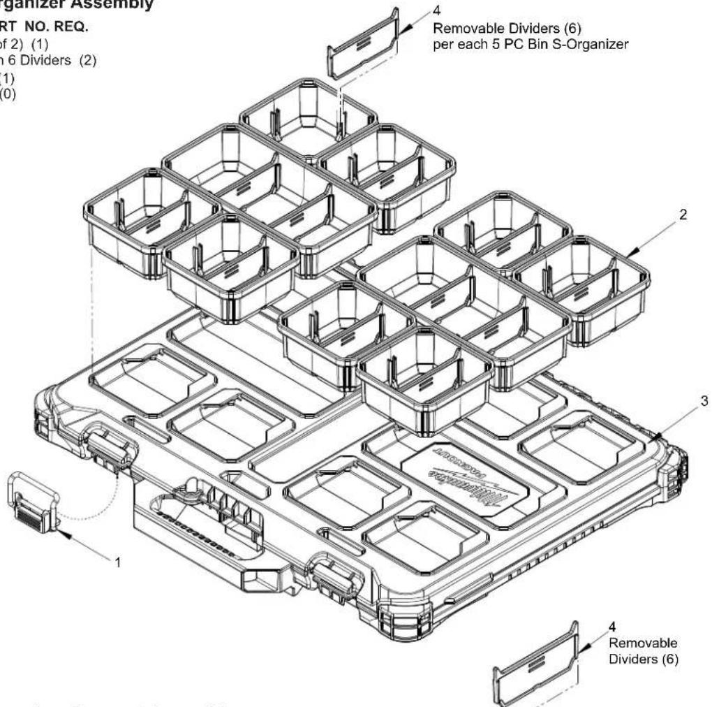
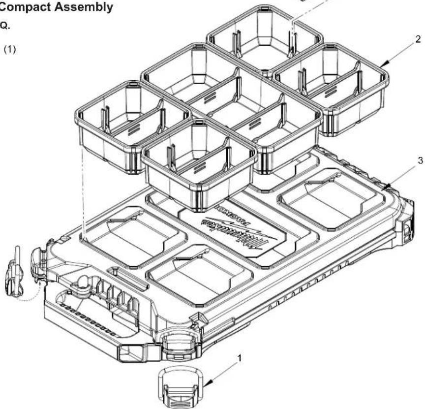
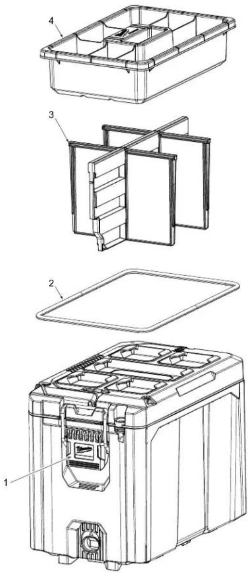
48-22-8436 PACKOUT™ S-Organizer Compact Assembly
FIG. PART NO. DESCRIPTION OF PART NO. REQ.
1 44-20-8436 LP Compact Org Latch (Set of 2) (1)
2 31-01-0502 5 PC Bin S-Organizer with 6 Dividers (1)
3 43-44-8435 Lid Gasket (Not Shown) (1)
4 31-01-0503 Spare Divider Kit, 6 pcs. (0)
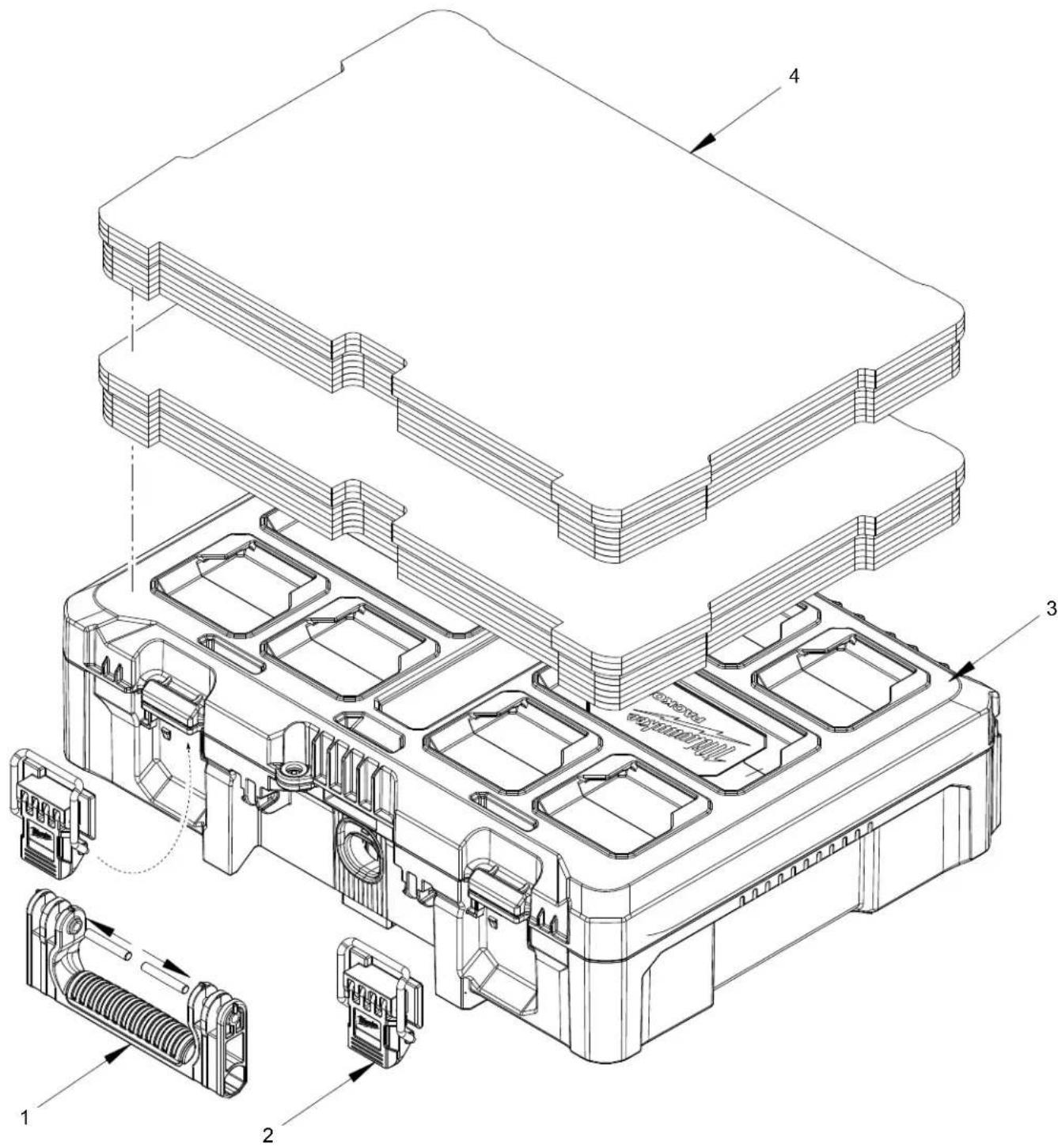
48-22-8450 PACKOUT™ Tool Box Kit with Foam Dividers
FIG. PART NO. DESCRIPTION OF PART NO. REQ.
1 43-62-8450 Kit Box Mono Block Handle with 2 Pins (1)
2 44-20-8430 Latch Service Assembly (Set of 2) (2)
3 43-44-8400 Lid Gasket (Not Shown) (1)
4 48-22-8455 Foam Insert for PACKOUT™ Kit Box (Set of 2) (1)
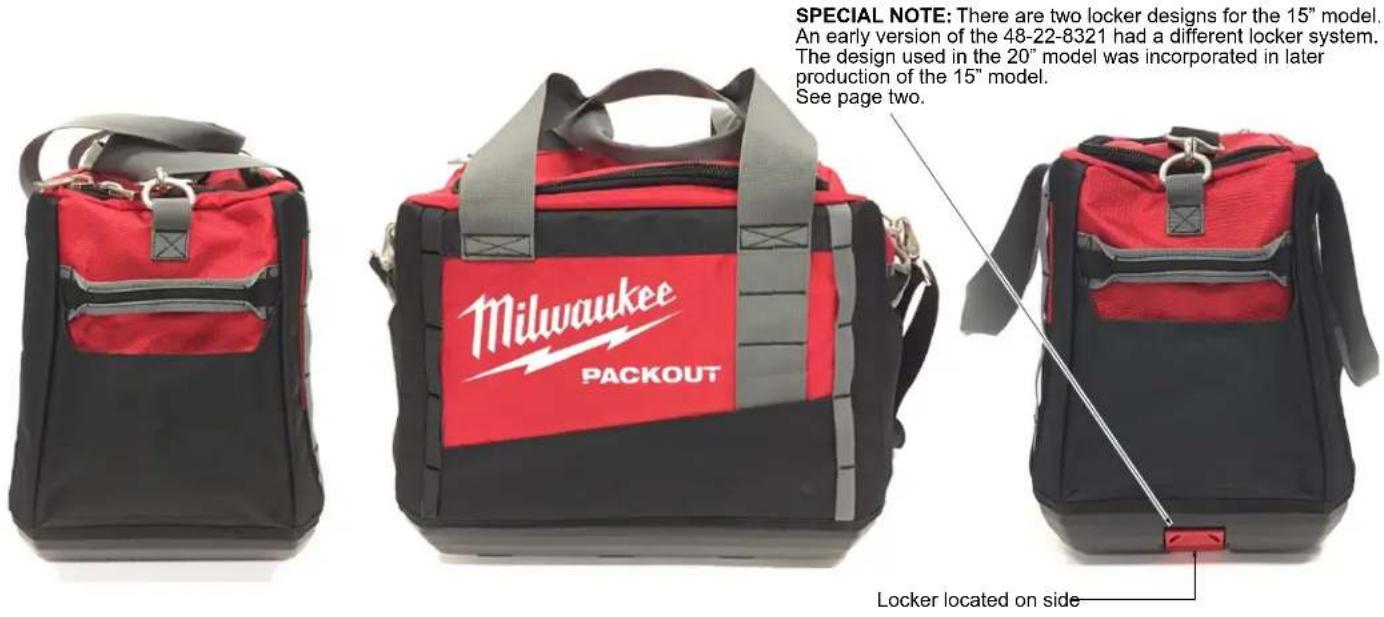
48-22-8321 15" PACKOUT™ (Medium) Tool Bag*
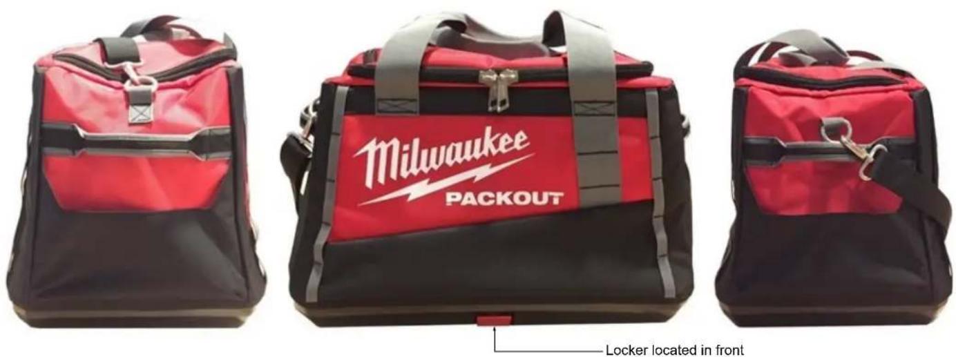
48-22-8322 20" PACKOUT™ (Large) Tool Bag*
*48-22-8321 15" PACKOUT™ (Medium) Tool Bag
*48-22-8322 20" PACKOUT™ (Large) Tool Bag
FIG. PART NO. DESCRIPTION OF PART NO. REQ.
1 45-56-8300 Shoulder Strap (For both tote models) (1)
2 44-20-8300 Locker Kit (For early versions of 48-22-8321)
See page two (1)
3 44-20-0305 Locker (For 48-22-8322 and later versions of 48-22-8321) See page 5 (1)
SEE PAGE 5 FOR INSTRUCTIONS ON REMOVING SELECTION AND INSTALLING BOTH LOCKER SYSTEMS
natural_image
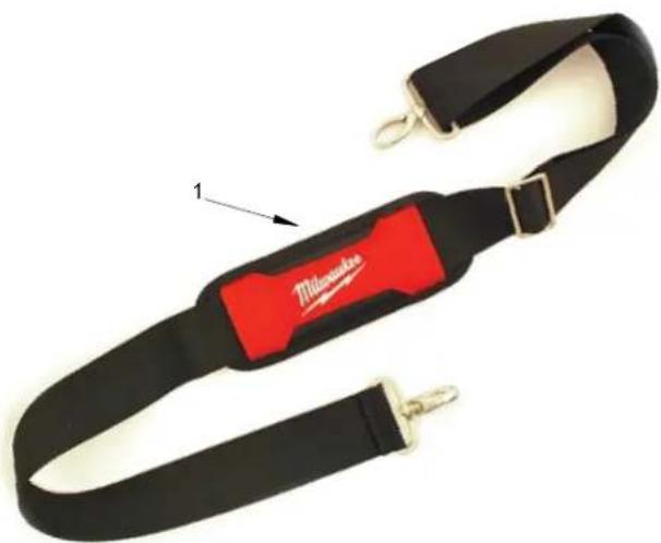
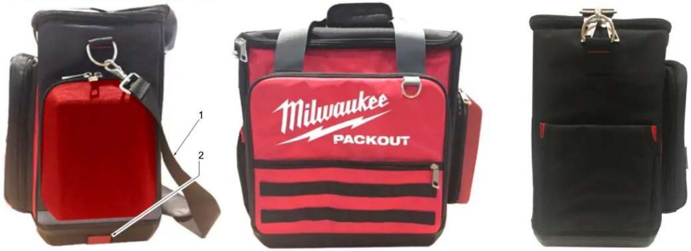
Black and red striped fabric belt with attached clips, no visible text or symbols48-22-8300 PACKOUT™ Tech Bag
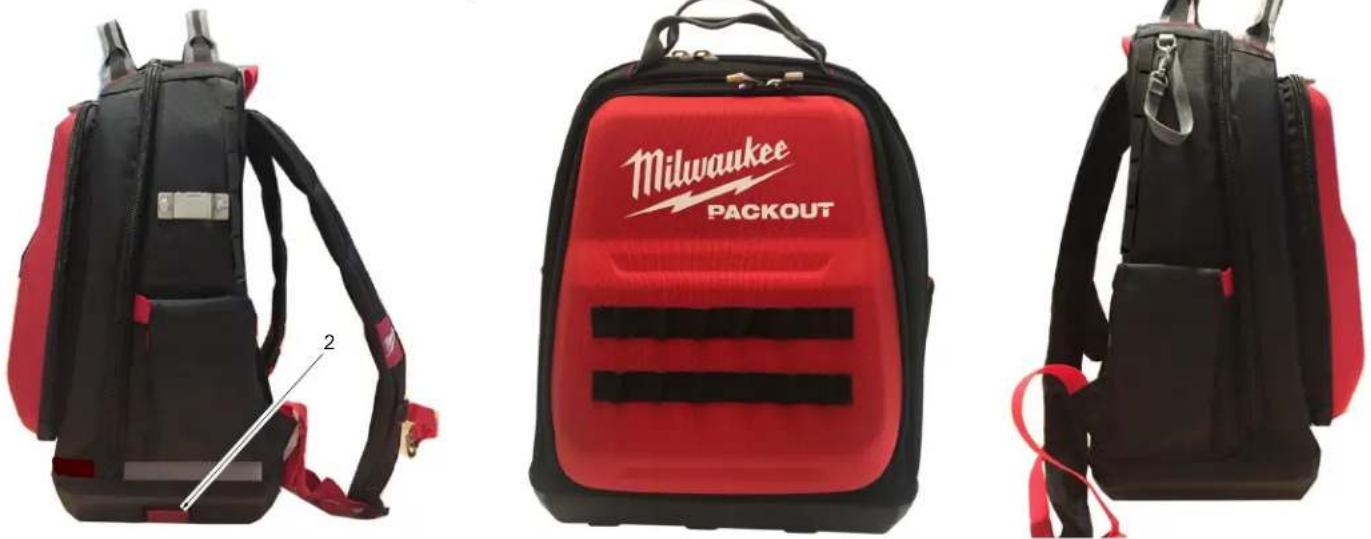
48-22-8301 PACKOUT™ Jobsite Backpack
48-22-8302 PACKOUT™ Jobsite Cooler
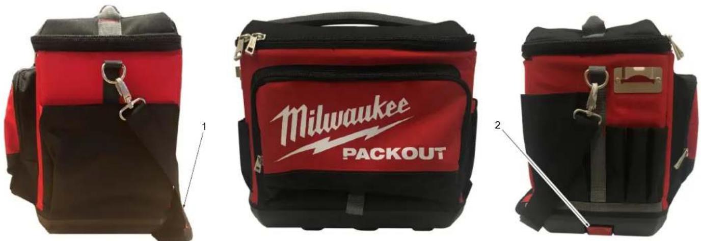
FIG. PART NO. DESCRIPTION OF PART NO. REQ.
1 45-56-8300 Shoulder Strap (For Cooler & Tech Bag) (1)
2 44-20-0305 Locker System (1)
SEE PAGE 5 FOR INSTRUCTIONS ON REMOVING AND INSTALLING BOTH LOCKER SYSTEMS
natural_image
Black and red fitness belt with attached straps and connector pins (no text or symbols visible)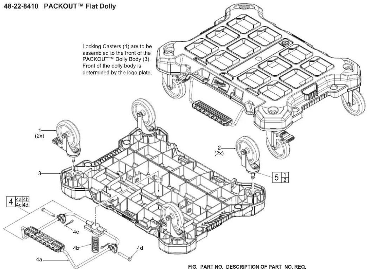
1 ---- Locking Swivel Caster (2)
2 Swivel Caster (2)
3 Dolly Base (1)
4 14-04-8410 Dolly Foot Brake Kit (1)
4a Dolly Foot Brake (1)
4b Spring (1)
4c ———— Cotter Pin (2)
4d Retaining Pin (2)
5 45-94-8410 Swivel Caster Kit (Set of 4) (1)
Note:
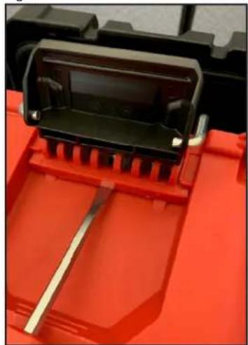
Procedure for removal and installation of the 44-20-8422 Latch (1).
Removal:
1. Undo latch from PACKOUT lid.
2. Insert a flathead screwdriver in-between latch assembly and PACKOUT base to pry over the tabs. (Fig.1)
3. Pull metal latch down to remove.
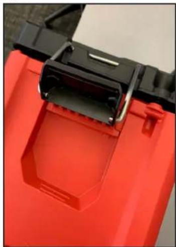
Installation:
1. Insert Latch Assembly into channel.
2. Attach the metal latch to the lid. (Fig.2)
3. Close latch to secure Latch Assembly in place inside the channel.
48-22-8422 PACKOUT™ Compact Toolbox
FIG. PART NO. DESCRIPTION OF PART NO. REQ.
| 1 | 44-20-8422 | Latch Assembly | (1) |
| 2 | 43-44-8422 | Gasket | |
| 3 | 31-01-8423 | Dividers | (1) |
| 4 | 31-01-8422 | Tray | (1) |
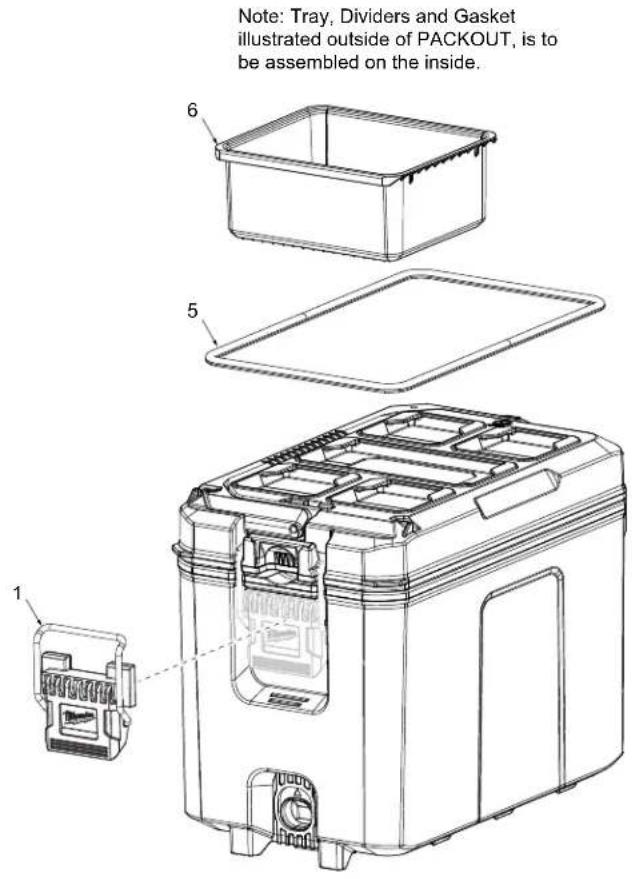
Fig.1
natural_image
Close-up of a red plastic electronic component with a black connector and a metallic rod inserted (no visible text or symbols)Fig. 2
natural_image
Close-up of a red plastic container with black plastic clip and metal bracket (no visible text or symbols)48-22-8460 PACKOUT™ Compact Cooler
| FIG. PART NO. DESCRIPTION OF PART | NO. REQ. | |
| 1 | 44-20-8422 Latch Assembly | (1) |
| 5 | 31-01-8460 Tray | (1) |
| 6 | 43-44-8460 Gasket | (1) |
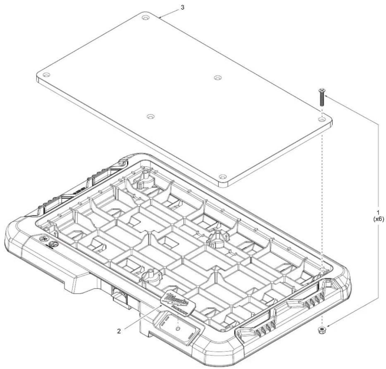
48-22-8488 PACKOUT™ Customizable Work Surface
FIG. PART NO. DESCRIPTION OF PART NO. REQ.
1 14-46-8488 Hardware Kit 6 sets (1)
2 31-01-8488 Logo Plate (1)
3 45-64-8488 Wood Top (1)
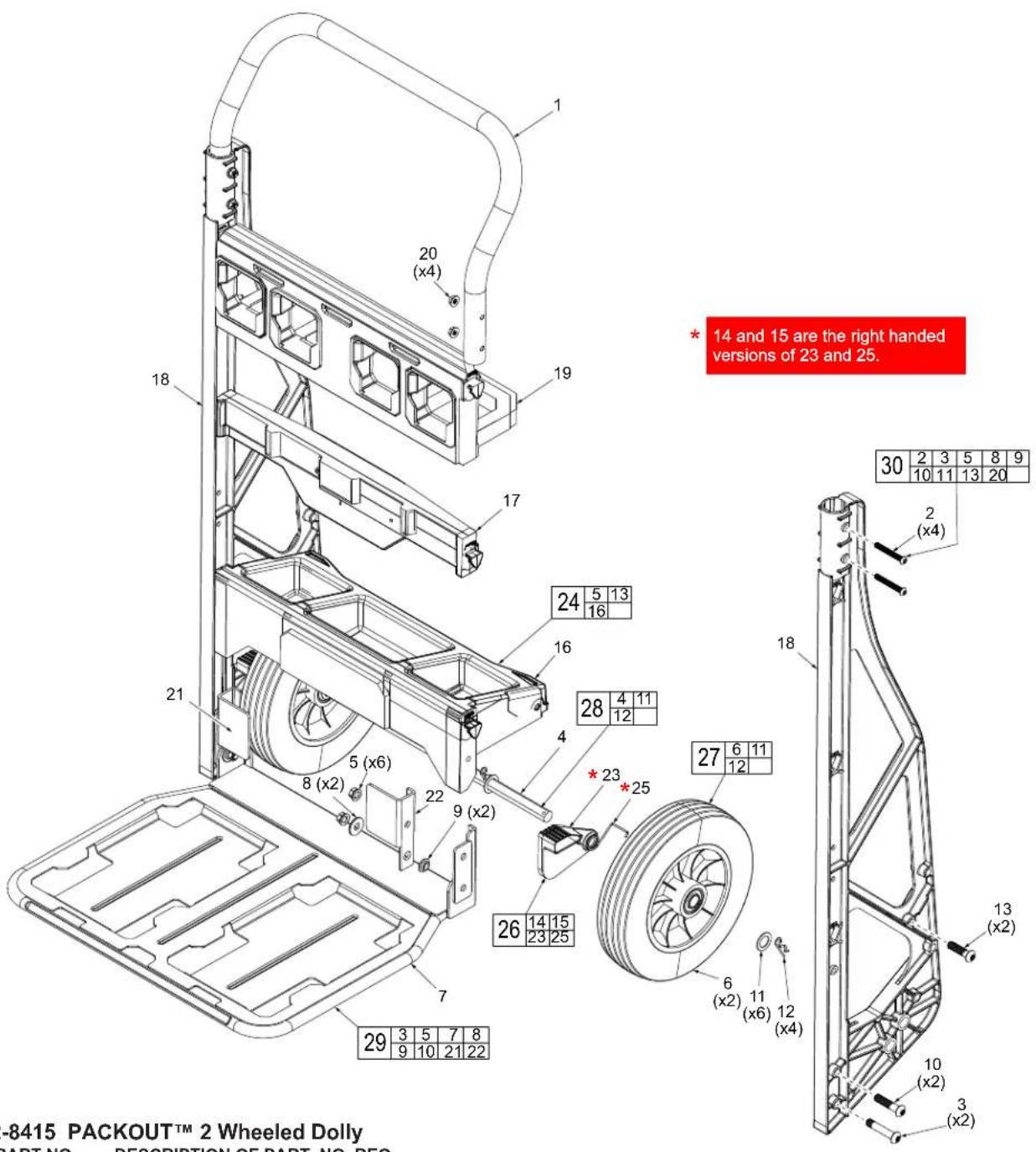
48-22-8415 PACKOUT™ 2 Wheeled Dolly
FIG. PART NO. DESCRIPTION OF PART NO. REQ.
1 ---- Handle (1)
2 20 x 1.875" Bolts (4)
3 3/8-16 x 2 Bolts (2)
4 Axle (1)
5 3/8-16 Lock Nut (6)
6 Wheel (2)
7 Base Plate (1)
8 Washer (2)
9 ——— Nylon Shoulder Washer (2)
10 3/8-16 x 1.75" Bolts (2)
11 5/8" Bushing Washers (6)
12 ---- Hitch Pin (4)
13 3/8-16 x 1.5" Bolts (2)
14 Right Spring (Not Shown) (1)
15 Toe Plate Lock Right (Not Shown) (1)
16 31-01-8415 Bottom Tray (1)
17 31-86-8415 Logo Cross Member (1)
18 Side Frame (2)
19 31-10-8415 PACKOUT Cross Member (1)
20 ---- Handle Nut (4)
21 Right Lock/Fender Assembly (1)
FIG. PART NO. DESCRIPTION OF PART NO. REQ.
22 ---- Left Lock/Fender Assembly (1)
23 Toe Plate Lock Left (1)
24 31-01-8415 Bottom Tray Kit (1)
25 Left Spring (1)
26 31-52-8415 Toe Plate Lock Kit (1)
27 45-94-8415 Wheel Kit (1)
28 42-12-8415 Axle Kit (1)
29 42-36-8415 Toe Plate Kit (1)
30 14-46-8415 Hardware Kit (1)


- 48-22-8425 PACKOUT™ (Large) Tool Box
- PART NO. DESCRIPTION OF PART NO. REQ.
- 48-22-8424 PACKOUT™ (Medium) Tool Box
- 48-22-8430 PACKOUT™ Organizer
- 48-22-8435 PACKOUT™ Compact Organizer
- 48-22-8431 PACKOUT™ S-Organizer Assembly
- 48-22-8436 PACKOUT™ S-Organizer Compact Assembly
- 48-22-8450 PACKOUT™ Tool Box Kit with Foam Dividers
- 48-22-8488 PACKOUT™ Customizable Work Surface
- 48-22-8415 PACKOUT™ 2 Wheeled Dolly
Marke : MILWAUKEE
Modell : 48-22-8436
Kategorie : Nicht kategorisiert