
Broadcaster - Mikrofon RODE - Kostenlose Bedienungsanleitung
Finden Sie kostenlos die Bedienungsanleitung des Geräts Broadcaster RODE als PDF.


| Produkttyp | Kondensatormikrofon für Rundfunk |
| Marke | RØDE |
| Modell | Broadcaster |
| Kapsel | 1 Zoll, extern vorgespannt, goldbedampfte Membran |
| Richtcharakteristik | Nierencharakteristik (Endadresse) |
| Frequenzgang | 20 Hz - 20 kHz |
| Ausgangsimpedanz | 40 Ω |
| Empfindlichkeit | -34 dB re 1 V/Pa (20 mV @ 94 dB SPL) ± 2 dB @ 1 kHz |
| Äquivalentes Rauschen | 14 dB SPL (A-bewertet, IEC651) |
| Maximaler Ausgangspegel | +2 dBu (@ 1 kHz, 1% THD an 1 kΩ Last) |
| Dynamikumfang | >114 dB SPL (A-bewertet, IEC651) |
| Maximaler Schalldruckpegel | 128 dB SPL (@ 1 kHz, 1% THD an 1 kΩ Last) |
| Signal-Rausch-Abstand | 80 dB (A-bewertet, IEC651) |
| Stromversorgung | Phantomspeisung P48 (48 V) / P24 (24 V) |
| Stromaufnahme | 5 mA (P48) / 4,5 mA (P24) |
| Gewicht (netto) | 577 g |
| Gehäuse | Edelstahl, robust |
| Besondere Merkmale | Schaltbarer Hochpassfilter, On-Air-LED-Anzeige, interner Popfilter |
| Mitgeliefertes Zubehör | RM2 Stativhalterung, 5-poliger On-Air-Adapter, ZP1 Aufbewahrungstasche |
| Garantie | 1 Jahr (erweiterbar auf 10 Jahre nach Online-Registrierung) |
Häufig gestellte Fragen - Broadcaster RODE
Benutzerfragen zu Broadcaster RODE
0 Frage zu diesem Gerät. Beantworten Sie die, die Sie kennen, oder stellen Sie Ihre eigene.
Eine neue Frage zu diesem Gerät stellen
Laden Sie die Anleitung für Ihr Mikrofon kostenlos im PDF-Format! Finden Sie Ihr Handbuch Broadcaster - RODE und nehmen Sie Ihr elektronisches Gerät wieder in die Hand. Auf dieser Seite sind alle Dokumente veröffentlicht, die für die Verwendung Ihres Geräts notwendig sind. Broadcaster von der Marke RODE.
BEDIENUNGSANLEITUNG Broadcaster RODE
R∅DE®
MICROPHONES

Broadcaster Instruction Manual
natural_image
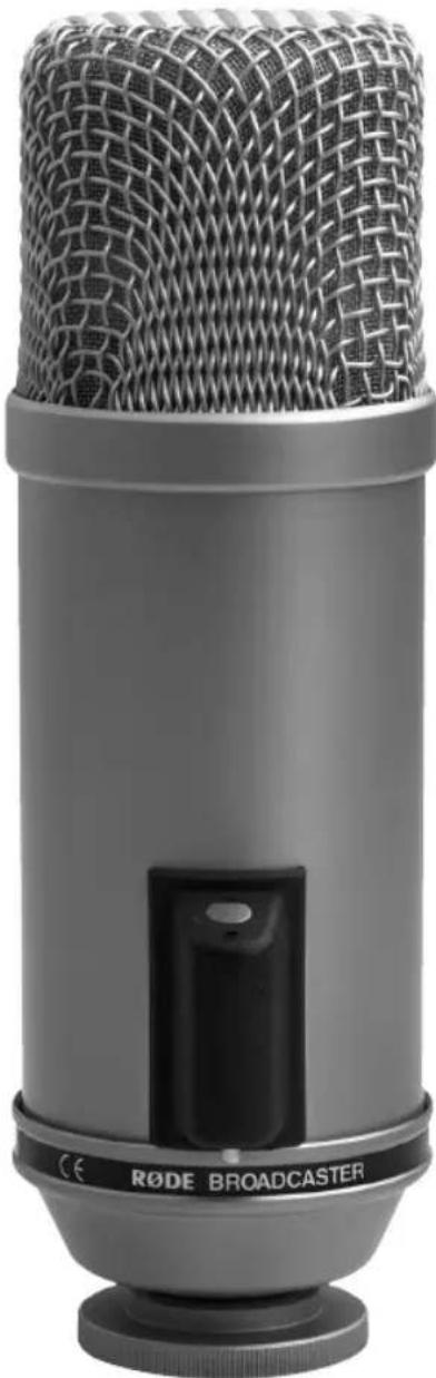
Close-up of a RøDE BROADCASTER audio recorder microphone (no visible text or symbols on body)www.rodemic.com
Introduction
We at RODE like to thank you and congratulate you on investing in the RODE Broadcaster.
Like its name suggests, this RODE microphone was specifically designed for 'ON-AIR' applications where wide frequency response and low distortion are demanded.
Winner of the Radio World/US National Association of Broadcasters (NAB) 'What's Cool' award, the Broadcaster has become an industry standard when studio sound quality is required for on-air applications.
Utilising an Australian designed and manufactured RODE 1" externally biased condenser transducer, the Broadcaster features a switchable high-pass filter to remove low frequency rumble.
A unique 'ON-AIR' LED indicator can be switched on or off by shorting contacts on the five pin audio connector. This feature allows console operators to warn the 'Talent' that the mic is live. More information on integrating this feature is available in this user manual.
Please take the time to visit www.rodemic.com and register your microphone for a full ten year warranty.
While there you can view studio tips and techniques, as well as browse the comprehensive range of accessories for RODE microphones.
Peter Freedman
R∅DE Microphones Sydney, Australia
Specifications
Acoustic Pressure gradient
Principle:
Directional Cardioid-end address
Pattern:
Frequency 20 Hz-20 kHz
Range:
Output 40Ω
Impedence:
Sensitivity: -34 dB re 1 Volt/Pascal (20 mV @
94 dB SPL) +/- 2 dB @ 1kHz
Equivalent Noise: 14 dB SPL
(A - weighted per IEC651)
Maximum +2dBu
Output: (@ 1kHz, 1% THD into 1KΩ load)
Dynamic Range: >114 dB SPL
(A - weighted per IEC651)
Maximum SPL: 128dB SPL
(@ 1kHz, 1% THD into 1KΩ load)
Signal/Noise: 80 dB
(A - weighted per IEC651)
Power P48 (48V), P24 (24V) phantom
Requirement: supply
Current 5 mA (P48)
Consumption: 4.5mA (P24)
Net Weight: 577gm
Specifications
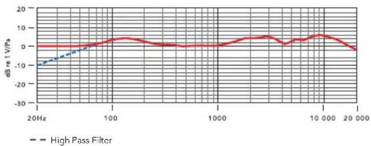
Frequency Response
line
| Frequency | High Pass Filter (dB re⁻¹ V/PA) | | --------- | ------------------------------- | | 20Hz | -10 | | 100 | 5 | | 1000 | 0 | | 10000 | 5 | | 20000 | 0 |Polar Response
radar
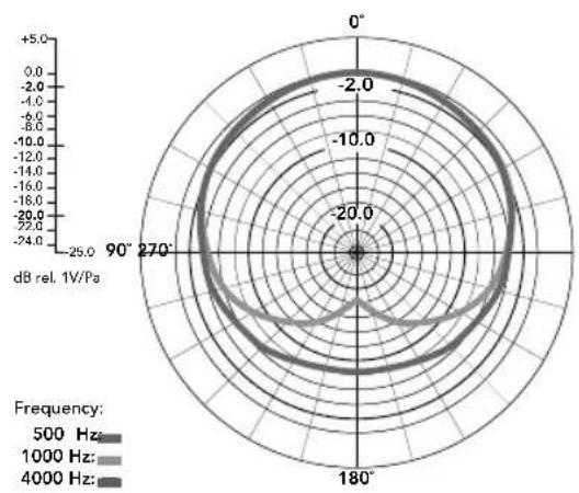
| Frequency | Angle (°) | Value (dB rel. 1V/Pa) | | --------- | --------- | --------------------- | | 500 Hz | 90 | -2.0 | | 500 Hz | 270 | -2.0 | | 500 Hz | 180 | -2.0 | | 1000 Hz | 90 | -2.0 | | 1000 Hz | 270 | -2.0 | | 1000 Hz | 180 | -2.0 | | 4000 Hz | 90 | -2.0 | | 4000 Hz | 270 | -2.0 | | 4000 Hz | 180 | -2.0 |Features
- 1" capsule with gold plated diaphragm
- On-Air indicator LED
- Ultra low noise
• Voice tailored switchable low-cut feature
- Internal pop filter
• Rugged stainless steel body
• Made in Australia
• 10 Year warranty*
*Online product registration required.
Accessories
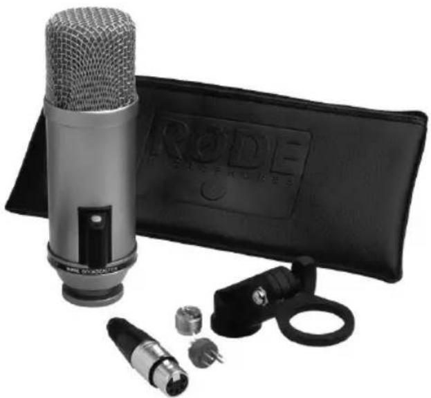
natural_image
Black and white photo of a studio microphone setup with a CD/DVD case, USB connectors, and a strap (no visible text or symbols)- RM2 stand mount
- 5 pin 'on-air' indicator adaptor
- ZP1 zip pouch
Using the Broadcaster
- The Broadcaster is a phantom powered microphone. To operate correctly it requires a 48V phantom supply from the mixing console or other source.
- It is recommended that you use a high-quality microphone lead, and keep it as short as practical for your stage set up. This will ensure the highest quality sound reproduction.
- The Broadcaster is an 'end address' microphone, so should be addressed with the microphone mounted lengthways, talking directly in to the head.
- Please ensure all cable connections are secure before applying power to the microphone, and allow a few moments for the microphone to stabilise after the power is turned on.
- Microphone technique, or how to get the sound you want, requires experimentation. Moving closer to the microphone increases the perceived 'warmth' and 'bass' (Proximity Effect). Try to get the sound you want by placing either reflective or absorbent panels at various angles adjacent to the source. Changing the acoustic properties of the space around the microphone is our recommended initial approach for obtaining the best sound quality.
Setting the High Pass Filter
- The High-Pass Filter setting can be used to reduce the microphone's sensitivity to low frequency sounds, and is useful when you wish to avoid additional noise and vibration from outside traffic, air conditioning and machinery, foot tapping etc.
Using the Broadcaster
- The High Pass Filter can be engaged using the toggle switch at the rear of the microphone.
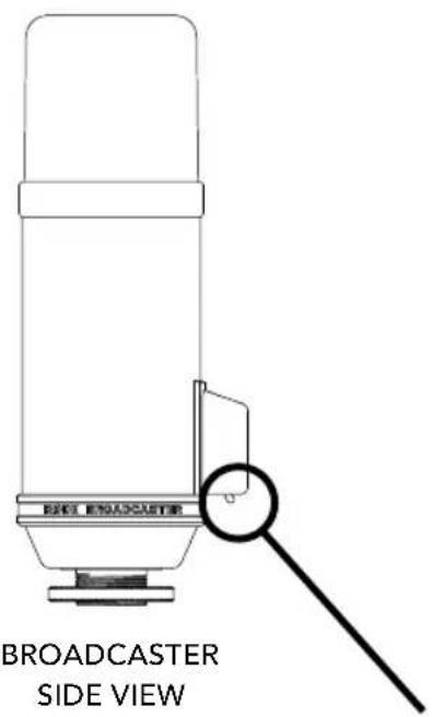
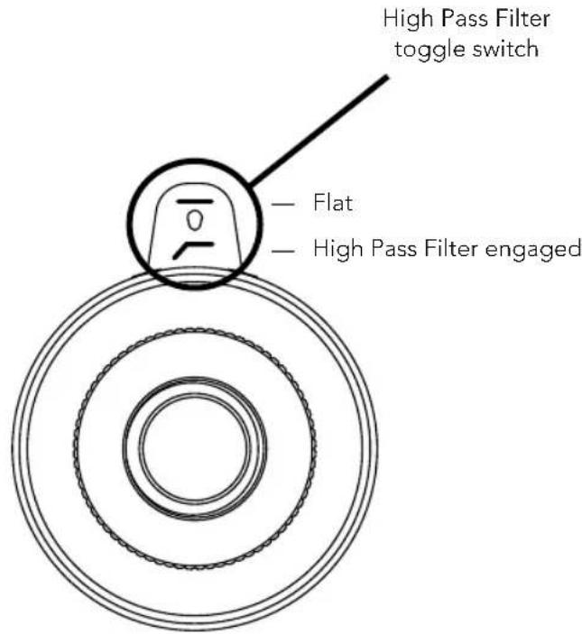
BROADCASTER BOTTOM VIEW
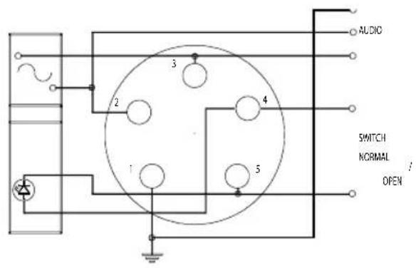
- While the broadcaster's output connection and 'On-Air' indicator control is a very simple operation to perform, we suggest that unless you are familiar with cable connections and audio installations in general, that you have an Audio/Electronics Technician perform this task to assure optimum performance.
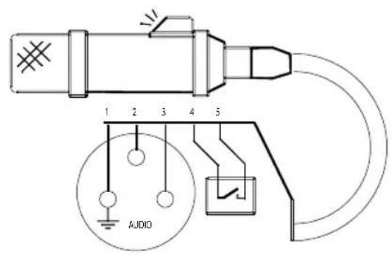
- The On-Air Indicator LED is switched either On or Off by applying an open or closed circuit across Pins 4 and 5 of the output connector.
- When 'open circuit' (no connections across Pins 4 and 5), the LED is active. If you do not wish to switch the LED via a console or separate mute button, then the LED will be active continuously whenever the microphone has P48V (Phantom Power) applied.
- Most professional consoles have switches that provide both open circuit or short circuit outputs. These are usually called 'Channel On' or 'Channel Mute' controls and actually mute the audio signal as well as providing external contacts. These external contacts are usually used to mute audio monitors and switch On-Air lights at the same time as microphones become active. These contacts can also be used to activate the broadcaster's 'On-Air' indicator.
- Remember, the LED does not interfere with the audio circuit, and has no other function than that of an indicator. The microphone does not mute itself! The indicator is simply that; an indicator of the status of what another device is doing.
Connecting the 'on-air' LED
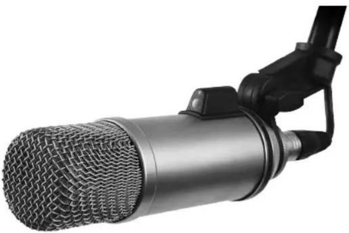
natural_image
Close-up of a metallic studio microphone with mesh grille and black clasp (no text or symbols visible)- A 5-pin female connector is supplied, and you can use a four-core screened (Quad) microphone cable which is readily available from most professional audio suppliers, or you can use any cable which is two wire screened plus two extra control wires if the LED is to be switched.
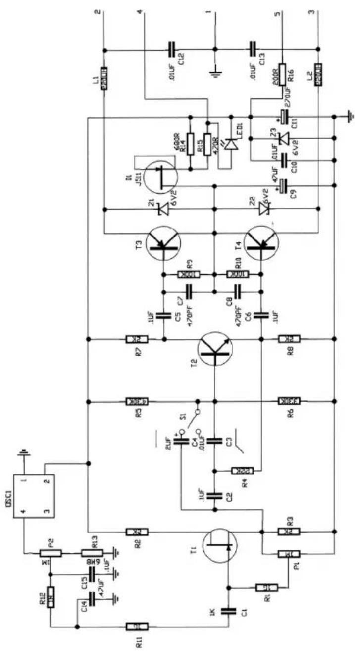
Circuit Diagram
Storage
- After use the Broadcaster should be removed from its mount, wiped with a dry, soft cloth and placed in its protective case.
- Be sure to place the moisture-absorbent crystals (supplied) at the head of the microphone, so as to absorb any moisture present.
- Eventually this pack of crystals will need to be dried. This is indicated by the crystals turning pink in colour.
- They can easily be re-used by placing them in an oven at 100 - 150 degrees celsius for approximately ten minutes. The crystals will operate effectively again once they have turned blue.
Warranty
All RODEphones are warranted for one year from date of purchase. You can extend that to a full ten years if you register online at www.rodemic.com.
The warranty covers parts and labour that may be required to repair the microphone during the warranty period. The warranty excludes defects caused by normal wear and tear, modification, shipping damage, or failure to use the microphone as per the instruction guide.
If you experience any problem, or have any questions regarding your RODE microphone, first contact the dealer who sold it to you. If the microphone requires a factory authorised service, return will be organised by that dealer.
We have an extensive distributor/dealer network, but if you have difficulty getting the advice or assistance you require, do not hesitate to contact us directly.
R∅DE Microphones
International
PO Box 6685
Silverwater NSW 2128 Australia
Ph: +61 2 9648 5855
Fax: +61 2 9648 2455
USA
P.O. Box 4189
Santa Barbara, CA 93140-4189
Ph: 805 566 7777
Fax: 805 566 0071
Technical Support
For information and technical support questions contact: support@rodemic.com
In the United States and Puerto Rico, contact usasupport@rodemic.com or call 425 398-1910
In Australia, contact ozsupport@rodemic.com or call (02) 9648 5855
Anywhere except Australia, the United States and Puerto Rico, contact support@rodemic.com or call +61 2 9648 5855


Marke : RODE
Modell : Broadcaster
Kategorie : Mikrofon