JH 15 - Chauffe-eau instantané et chauffe-eau Joven - Kostenlose Bedienungsanleitung
Finden Sie kostenlos die Bedienungsanleitung des Geräts JH 15 Joven als PDF.


Benutzerfragen zu JH 15 Joven
0 Frage zu diesem Gerät. Beantworten Sie die, die Sie kennen, oder stellen Sie Ihre eigene.
Eine neue Frage zu diesem Gerät stellen
Laden Sie die Anleitung für Ihr Chauffe-eau instantané et chauffe-eau kostenlos im PDF-Format! Finden Sie Ihr Handbuch JH 15 - Joven und nehmen Sie Ihr elektronisches Gerät wieder in die Hand. Auf dieser Seite sind alle Dokumente veröffentlicht, die für die Verwendung Ihres Geräts notwendig sind. JH 15 von der Marke Joven.
BEDIENUNGSANLEITUNG JH 15 Joven
Thank you for selecting JOVEN Storage Water Heater. Please read this manual before installation and be sure to keep it handy for your future reference.

SAFETY PRECAUTION
This sign warns of serious injury, damage to property and potential death. Before operating, please read the following "Safety Precautions" carefully.
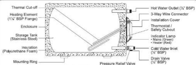
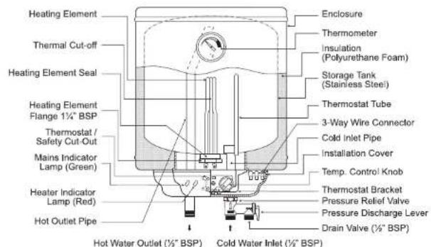
1 PARTS IDENTIFICATION
text_image
Thermal Cut-off Heating Element (1½" BSP Flange) Enclosure Storage Tank (Stainless Steel) Insulation (Polyurethane Foam) Mounting Ring Hot Water Outlet (½" BSP) 3-Way Wire Connector Installation Cover Thermostat / Safety Cut-out Indicator Lamp • Mains (Green) • Heater (Red) Cold Water Inlet (½" BSP) Drain Valve (½" BSP) Pressure Relief ValveHORIZONTAL MOUNTING
Optional Built-In Heat Elevator
CAPACITY : 15, 25, 35, 38, 50, 56, 68 & 91 (LITRES)
text_image
Heating Element Thermal Cut-off Heating Element Seal Heating Element Flange 1½" BSP Thermostat / Safety Cut-Out Mains Indicator Lamp (Green) Heater Indicator Lamp (Red) Hot Outlet Pipe Enclosure Thermometer Insulation (Polyurethane Foam) Storage Tank (Stainless Steel) Thermostat Tube 3-Way Wire Connector Cold Inlet Pipe Installation Cover Temp. Control Knob Thermostat Bracket Pressure Relief Valve Pressure Discharge Lever Drain Valve (½" BSP) Hot Water Outlet (½" BSP) Cold Water Inlet (½" BSP)VERTICAL MOUNTING
CAPACITY : 25, 35 & 50 (LITRES)
2 TRIPLE SAFETY SYSTEM (TSS)
The Triple Safety System (TSS) in the heater incorporates the Pressure Relief Valve, the Thermostat with Safety Cut-out and Thermal Fuse.
- Pressure Relief Valve
The Pressure Relief Valve prevents excessive pressure built-up in the storage tank and must not be removed or replaced. In the event the pressure in the storage tank exceeds 0.9 ± 0.1 MPa ( 9 ± 1 Bar), the drain valve will operate and vent the water through the overflow pipe which must not be closed or blocked. The pressure discharge Lever makes it easy to discharge water from the storage tank when changing the heating element or remove any blockage at the drain valve.

IMPORTANT
Operate the pressure discharge level at least once year to prevent blockage at the drain valve. Closed or blocked drain valve may cause serious damage to the heater tank and void the warranty.
- Thermostat
CAUTION: The heater must not operate without the Thermostat.
i.) Horizontal Model
The Thermostat incorporates a pre-set temperature and a Safety Cut-out with manual reset. Under normal operation the Thermostat cuts out at approximately 65°C to 70°C (depends on requirement) which is the most economical setting with lower heat loss and less lime scaling. This is indicated by the Red Lamp going off and comes on again when the water temperature drops as hot water is drawn off. Thus maintaining a constant supply of hot water.
ii.) Vertical Model
A control knob is provided on the surface of the installation cover for adjusting the temperature of the water heater from 'OFF' to 70°C (Low - Med - High). Under normal operation the Thermostat cuts out at the set temperature - Low (about 40°C), Medium (about 55°C), High (about 70°C).
Economical Mode
When the hot water consumption required is not in large volume, setting Adjustable Thermostat at Medium will minimize the electrical consumption.
iii.) Safety Cut-out (Horizontal & Vertical Model)
The Safety Cut-out will break the circuit to the heating element in any event the water temperature in the storage tank becomes excessively high (95°C). This is indicated by the Red and Green Lamps going off.
CAUTION: Should this happen, switch off the heater electrical supply point and contact our nearest service centre or sales agent. Do not attempt to repair the heater yourself.
- Thermal Cut-Off
The Thermal Cut-Off helps to prevent the heating element from being damaged in any event the heater operates without water.

Optional Built-In Heat Elevator
This energy saving Heat Elevator uses patent pending magnetic technology to accelerate convective heat transfer of fluids. The result is faster water heating time and ensures a more constant and uninterrupted flow of hot water.
3 INSTALLATION INSTRUCTION
3.1 WATER HEATER INSTALLATION

IMPORTANT
- Installation should be carried out by qualified personnel with close reference to the installation manual and compliance to the local authority.
- All plumbing works must be completed and heater tank fully filled with water before proceeding to electrical connections. This will prevent any damage to the Heating Element and Thermal Fuse.
• This appliance must be installed indoor only.
- Do not use ABS or PVC plastic pipes for the inlet and outlet pipe connections. Use only recommended Stainless Steel, Copper or Polymer pipe which can withstand high temperature and pressure.
- Do not install in area where the water supply EXCEED 20mg/LITRE (20ppm) OF CHLORIDE as this will cause corrosion to the stainless steel heater tank and void the warranty.
- Select a suitable location for convenience of water and electrical supply as well as easier for future maintenance. Make sure the location is free from water splash.
-
In case the water supply is from the water tank, the water heater should be connected to a booster pump (minimum 0.15MPa/1.5bar), in order to have sufficient hot water flow.
-
For Horizontal Model (JH)
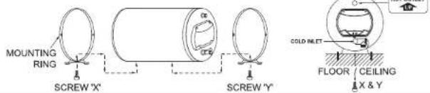
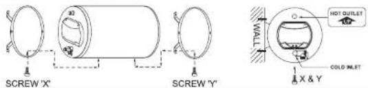
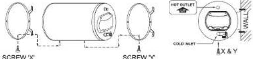
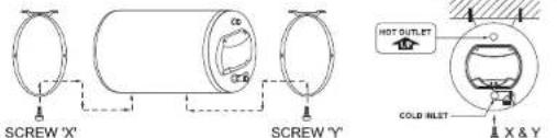
3.1 Remove screw 'X' and 'Y' from the heater and position the mounting rings to the desired mounting position, according to the type of mounting position required. (Refer FIGURE A)
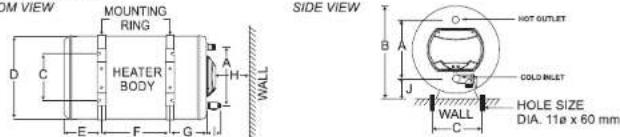
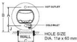
3.2 Mark and drill 4 holes (11mm Dia. X 60mm depth) with dimension 'C' and 'F'. (Refer FIGURE B)
3.3 Insert the expansion bolts firmly to the holes and remove the hex nuts and washers.
3.4 Mount the mounting rings in position to the expansion bolts.
CAUTION: Ensure the inlet pipe is at the lower position. (Refer FIGURE A)
3.5 Securely fasten the washers and hex nuts. Reinstall screw 'X' and 'Y'
- For Vertical Model (JVA):
4.1 Mark and drill 2 holes (11mm Dia. X 60mm depth) with dimension 'C' and 'F' (Refer FIGURE B)
4.2 Insert the expansion bolts firmly to the holes and remove the hex. nuts and washers.
4.3 Mount the mounting bracket in position to the expansion bolts.
CAUTION: This water heater is designed for vertical mounting to the wall only.
4.4 Securely fasten the washers and hex nuts.
FIGURE A: MOUNTING RINGS POSITION FOR HORIZONTAL MODEL
① TOP MOUNTING (ON CEILING OR FLOOR)
text_image
MOUNTING RING SCREW 'X' SCREW 'Y' COLD INLET FLOOR CEILING X & Y② LEFT HAND SIDE MOUNTING (ON WALL)
text_image
SCREW 'X' SCREW 'Y' HOT OUTLET COLD MLET X & Y3 RIGHT HAND SIDE MOUNTING (ON WALL)
text_image
SCREW 'X' SCREW 'Y' HOT OUTLET COLD INLET X & Y WALL4 HANGING MOUNTING (ON CONCRETE CEILING)
text_image
SCREW 'X' SCREW 'Y' HOT OUTLET COLD INLET X & YFIGURE B: INSTALLATION DIMENSIONS
HORIZONTAL MODEL
text_image
M M VIEW MOUNTING RING HEATER BODY A H WALL E F G Side VIEW B A J HOT OUTLET COLD INLET HOLE SIZE DIA. 11ø x 60 mm WALL CREAR VIEW
VERTICAL MODEL
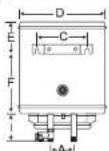
BOTTOM VIEW
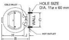
SPECIFICATIONS
| Model | Tank Capacity (Litres) | Dimensions (mm) | *Heating Element Wattage | Approx. Wt. Kgs (Empty/Full) | ||||||||||
| A | B | C | D | E | F | G | H | I | J | Standard | Option | |||
| JH 15 | 15(3.3 Imp. Gais) | 260 | 405 | 265 | 381 | 96 | 70 | 96 | 210 | 65 | 92 | 3kW 240 Va.c | 1.5kW 230 Va.c | 10/25 |
| JH 25 | 25(5.5 Imp. Gais) | 260 | 405 | 265 | 381 | 121 | 150 | 121 | 210 | 65 | 92 | 3kW 240 Va.c | 1.5kW 230 Va.c | 12/37 |
| JH 35 | 35(7.7 Imp. Gais) | 260 | 405 | 265 | 381 | 121 | 269 | 121 | 210 | 65 | 92 | 3kW 240 Va.c | 1.5kW 230 Va.c | 14/49 |
| JH 38 | 38(8.4 Imp. Gais) | 260 | 405 | 265 | 381 | 121 | 304 | 121 | 210 | 65 | 92 | 3kW 240 Va.c | 1.5kW 230 Va.c | 15/53 |
| JH 50 | 50(11.0 Imp. Gais) | 260 | 405 | 265 | 381 | 121 | 438 | 121 | 210 | 65 | 92 | 3kW 240 Va.c | 1.5kW 230 Va.c | 17/67 |
| JH 56 | 56(12.3 Imp. Gais) | 260 | 405 | 265 | 381 | 121 | 508 | 121 | 210 | 65 | 92 | 3kW 240 Va.c | 1.5kW 230 Va.c | 18/74 |
| JH 68 | 68(15.0 Imp. Gais) | 260 | 405 | 265 | 381 | 121 | 648 | 121 | 210 | 65 | 92 | 3kW 240 Va.c | 1.5kW 230 Va.c | 20/88 |
| JH 91 | 91(20.0 Imp. Gais) | 260 | 405 | 265 | 381 | 121 | 914 | 121 | 210 | 65 | 92 | 3kW 240 Va.c | 1.5kW 230 Va.c | 25/116 |
| JVA 25 | 25(5.5 Imp. Gais) | 100 | 393 | 217 | 372 | 121 | 271 | - | 316 | 65 | 77 | 3kW 240 Va.c | 1.5kW 230 Va.c | 12/37 |
| JVA 35 | 35(7.7 Imp. Gais) | 100 | 393 | 217 | 372 | 121 | 390 | - | 316 | 65 | 77 | 3kW 240 Va.c | 1.5kW 230 Va.c | 14/49 |
| JVA 50 | 50(11.0 Imp. Gais) | 100 | 393 | 217 | 372 | 121 | 559 | - | 316 | 65 | 77 | 3kW 240 Va.c | 1.5kW 230 Va.c | 17/67 |
*Heating Element Wattage from 0.5kW to 3kW 220 -240 Va.c on request.
Horizontal Model Vertical Model
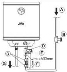
3.2 PLUMBING CONNECTION (Refer FIGURE C)
-
Install 1 or 2 unit of Check Valve to 12 " BSP connection at end of Pressure Relief Valve (with Blue Cap).
-
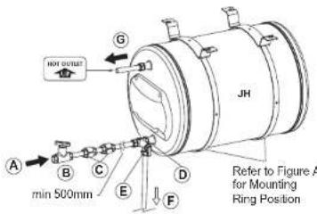
The Position of the check valve(s) must not be too close to the Pressure Relief Valve. A length of 500mm is good for thermal expansion.
CAUTION: • The Pressure Relief Valve is for protection against excessive pressure in the heater tank and must not be removed or replaced. When the heating element operates, it is normal for water to drip from the Drain Valve. -
Connect cold water supply line to the check valve.
- Connect hot water line to the outlet pipe (with Red Cap)
- Connect a 15mm ( 12 ) diameter copper tube (maximum length 9 metres) to the Drain Valve end, leading downward to a drain that is open to the atmosphere and in a frost-free ambient, so that in the event of excessive pressure in the storage tank, the flow of water will not cause damage to the surroundings or critical areas of the building.
CAUTION: Drain Valve must not be closed or blocked which may cause serious damage to the heater tank and void the warranty.
FIGURE C: PIPING DIAGRAM
text_image
JVA A B C D E G min 500mm FA. Cold Water Inlet from Main Supply / Water Tank
B. Control Valve (Not Included)
C. Single or Double Check Valve (Not included)
D. Pressure Relief Valve
text_image
A min 500mm B C D E F G JH Refer to Figure A for Mounting Ring PositionE. Drain Valve (Must not be closed / blocked)
F. Overflow Pipe to Drain or floor trap
G. Hot Water Outlet to Mixer Tap
TO FILL HEATER TANK
- Open control valve in cold water supply line and all hot water faucets to allow trapped air to be vented out from the heater tank and piping.
- Allow the heater tank to completely fill with water as indicated by a steady flow of water from the hot water faucets without switching on the electrical supply.
- Turn off all hot water faucets. Check all pipe connections to ensure that they are properly sealed against leakage.
3.3 CONNECTION OF OVERFLOW PIPE
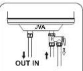
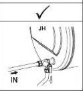
Connect Overflow pipe leading downward to drain or floor trap
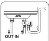
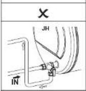
DO NOT connect
overflow pipe leading
upward
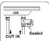
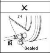
DO NOT Close or Block Drain Valve
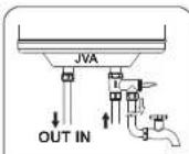
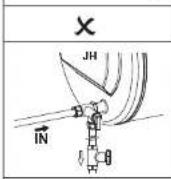
DO NOT connect overflow pipe to any valve
4 WIRING CONNECTIONS

IMPORTANT
- All plumbing works must be completed and heater tank filled with water before proceeding to electrical connections. This will prevent any damage to the unit.
- Ensure that the electrical supply is single-phase at 220 to 240 Va.c.
- It is recommended to install an approved current operated type Earth Leakage Circuit Breaker (ELCB) or Residual Current Circuit Breaker (RCCB) of 10mA sensitivity and higher than heater rated current. (Refer to Table 1)
- It is recommended to install an approved type Miniature Circuit Breaker(MCB) or Molded Case Circuit Breaker (MCCB) higher than heater rated current. (Refer to Table 1)
- Ensure that the wiring can supply the necessary amperage. (Refer to Table 1 for correct cable size)
- This water heater must be permanently connected to the electrical supply through a Double Pole Linked Switch above rated current (Refer to Table 1) and having contact separation of at least 3mm in all poles incorporated in the fixed wiring. The switch must be out of reach from user in the bathroom.
- Do not share the electrical supply with other appliances.
- Do not switch ON if there is a possibility that the water in the heater is frozen.
• THIS APPLIANCE MUST BE PERMANENTLY EARTHED
This water heater is completely factory wired to 3-way Connector with L(LIVE), N(NEUTRAL) and ⚙(EARTH) marking. 1. Switch off the electrical mains.
-
Remove installation cover screws of the heater.
-
Refer to Fig. 2, connect electrical wire as follow:
Brown
Blue
to N (NEUT
to ①(FARTH)
Green/Yellow to (EARTH)
-
Ensure that the copper wires are properly tightened on the 3-way Connector.
-
Replace the installation cover.
-
Provide sticker label if two heater ON/OFF switches are used to control it.
Fig. 1: Recommended Electrical Connection
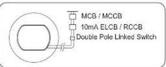
text_image
MCB / MCCB 10mA ELCB / RCCB Double Pole Linked SwitchFig. 2: Recommended Stripping Length
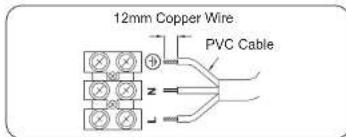
text_image
12mm Copper Wire PVC CableTable 1: Electrical Loading Table
| Power (kW) | Voltage (Va.c.) | Conductor Size (mm2) | Cable No. (No./ømm) | Rated Current for Circuit Breaker / Double Pole Linked Switch (A) |
| 1.37 to 1.63 | 220 to 240 | 2.0 | 40/0.25 | 16 |
| 2.50 to 3.00 | 220 to 240 | 2.5 | 70/0.25 | 20 |
5 SCHEMATIC WIRING DIAGRAM
HORIZONTAL MODEL
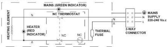
text_image
HEATING ELEMENT MAINS (GREEN INDICATOR) N NC THERMOSTAT HEATER (RED INDICATOR) A NC NC THERMAL FUSE N A 3-WAY CONNECTOR MAINS SUPPLY 220-240 Va.c N L© copyright 01/2012-02 JOVEN
VERTICAL MODEL
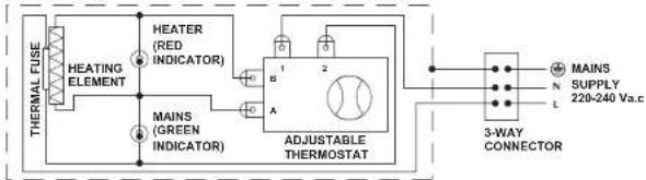
flowchart
graph TD
    A["HEATING ELEMENT"] --> B["HEATER (RED INDICATOR)"]
    A --> C["MAINS (GREEN INDICATOR)"]
    B --> D["ADJUSTABLE THERMOSTAT"]
    C --> D
    D --> E["3-WAY CONNECTOR"]
    E --> F["MAINS"]
    E --> G["SUPPLY"]
    E --> H["220-240 Va.c"]
6 OPERATION

IMPORTANT
• Make sure the heater tank is filled with water before switching on the electrical supply. Failure to do so will damage the heating element and void the warranty.
- To avoid the danger of scalding when operating this water heater, always turn on the cold water faucet first and then adjust the hot water faucet to get the desired water temperature.
- This appliance is not intended for use by young children or infirm persons without supervision.
The first operation and heating of the appliance must be observed by the installing technician after water and electrical connection have been made and heater tank filled with water, before switching on the electrical supply. The standard 3kW heating element (optional 1.5kW) together with automatic regulating thermostat (horizontal model) and an adjustable thermostat (vertical model), heat up water faster and keeps electric consumption to a minimum. In addition, the compact polyurethane foam insulation keeps the hot water longer and ready for immediate use.
STORAGE WATER HEATER HEATING CHART
• Approximate time taken to heat up to 70°C. Inlet water temperature at 27°C.
| MODEL | Tank Capacity (Litres) | Time Taken (Min) | Replacement Rate43°C Rise | |
| 3kW 240 Va.c | 1.5kW 230 Va.c | |||
| JH 15 | 15 (3.3 Imp. Gals) | 15 | 23 | 3 kW 240 Va.c Heating Element- 63 litres (14 gals) per hour |
| JH 25 | 25 (5.5 Imp. Gals) | 20 | 40 | |
| JH 35 | 35 (7.7 Imp. Gals) | 30 | 60 | |
| JH 38 | 38 (6.4 Imp. Gals) | 35 | 70 | |
| JH 50 | 50 (11.0 Imp. Gals) | 45 | 90 | |
| JH 56 | 56 (12.3 Imp. Gals) | 50 | 100 | |
| JH 68 | 68 (15.0 Imp. Gals) | 60 | 120 | |
| JH 91 | 91 (20.0 Imp. Gals) | 80 | 160 | |
| JVA 25 | 25 (5.5 Imp. Gals) | 20 | 40 | 1.5 kW 230 Va.c Heating Element- 32 litres (7 gals) per hour |
| JVA 35 | 35 (7.7 Imp. Gals) | 30 | 60 | |
| JVA 50 | 50 (11.0 Imp. Gals) | 45 | 90 | |
Horizontal Model Vertical Model
7 MAINTENANCE
Under higher temperature condition most water deposits lime scale. It is recommended to remove lime scale which has accumulated on the heating element and Pressure Relief Valve.
A. To Drain Out Water
-
Switch off the electrical supply.
-
Open any mixer tap to release some hot water and allow cold water to fill the heater tank. Beware of hot water in the heater tank. Release sufficient amount of hot water.
-
Close the cold water supply stop cock connected to the water heater inlet.
-
Lift up the lever on the pressure relief valve to start the draining of water. Check that the water is flowing at the drain valve end.
-
After the water in the heater tank is fully discharged, push down the lever on the pressure relief valve.
B. To Remove Heating Element
-
Remove the heater installation cover.
-
Disconnect wire to the thermostat and remove the heating element using the opener tool.

IMPORTANT
- After the maintenance, make sure the heater tank is completely refilled with water before switching on the electrical supply. Heating element will be damaged if electrical supply is switched on for even a short time while heater tank is dry or filling.
- Use any household cleaner for cleaning. Do not use abrasive cleaner or organic cleaner (petrol or alcohol).
8 TROUBLESHOOTING
- Check the following points for better performance:
| SYMPTOMS | POINT TO CHECK FOR REMEDY |
| A. No water coming out of the heater | Check whether all stop valves are opened.Check whether the water supply is there.Check whether the Pressure Relief valve over lighten.Check whether Inlet water supply connected to Pressure Relief Valve. |
| B. Water heater is not working | Check whether power supply is ON.Is the main lamp ON.Is the heater lamp ON.Is the adjustable temp. control ON. (JVA model)Is the mixer tap connected correctly. |
| C. Water not hot enough | Is the adjustable temp. control turn to maximum. (JVA model)Is the mixer tap adjusted correctly.Is the water heater given enough time to heat up. (If the temp. reaches the preset temp., the red heater lamp will go OFF automatically).Is the water heater capacity enough for the purpose |
- If any of the following abnormalities are present during usage, contact our service centres nearest to you or your sales agent immediately:
A. Water leakage
B. Water temperature cannot be controlled (JVA mode). C. Power and heater lamp does not light up.

IMPORTANT
NEVER TRY TO REPAIR THE UNIT YOURSELF
9 PRODUCT WARRANTY
WARRANTY VOID
- This warranty does not cover lightning, natural disaster, pest attacks, fire, negligence, misuses, accidents, floods, pollution, abuse or neglect, improper installation or improper maintenance and abnormal voltage or the usage of generator.
- Failure to follow the installation manual.
- Repair or attempted to repair this product by anyone not authorised by JOVEN.
- Any unit which has been altered or on which the serial number has been defaced, modified or removed.
- Water supply exceed 20mg/litre (20ppm) Chloride.
* Note: Refer to your local distributor for warranty terms & conditions
Manufactured by JOVEN ELECTRIC CO.