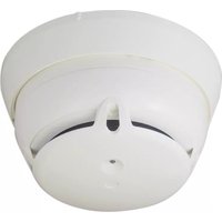
FDOOT271-O - Rauchmelder BOSCH - Kostenlose Bedienungsanleitung
Finden Sie kostenlos die Bedienungsanleitung des Geräts FDOOT271-O BOSCH als PDF.


| Produkttyp | Funk-Rauchmelder |
| Modell | FDOOT271-O |
| Marke | Bosch (Siemens) |
| Abmessungen (mit Sockel) | Höhe: 117 mm, Durchmesser: 100 mm |
| Gewicht (ohne Zubehör) | 0,132 kg |
| Stromversorgung | Batteriepack BAT3.6-10 (4 Lithium-Batterien + 1 Reserve) |
| Betriebstemperatur | -10 °C bis +55 °C |
| Lagertemperatur | -30 °C bis +75 °C |
| Luftfeuchtigkeit | ≤95 % rel. |
| Schutzart | IP44 |
| Funkfrequenz | 433,05–434,79 MHz und 868–870 MHz |
| Sendleistung | ≤10 mW ERP (433 MHz), ≤25 mW ERP (868 MHz) |
| Funktionen | Neuronaler Brandmelder, Wärmemelder, Rauchmelder, interner Alarmindikator (rot/grün), Renovierungsmodus, Testmodus |
| Ansprechempfindlichkeit (Rauch) | 2,3–12 %/m |
| Ansprechverhalten (Wärme) | A1R (60 °C) oder A1S (60 °C) |
| Montage | Auf Sockel FDB271, Befestigung mit zwei Schrauben |
| Wartung | Mindestens einmal jährlich Sichtprüfung und Funktionstest; Batteriewechsel bei Meldung „Batterie schwach“ |
| Reinigung | Keine spezifische Reinigung erforderlich; bei Verschmutzung vorsichtig reinigen (siehe Anleitung) |
| Sicherheitshinweise | Elektroinstallation nur durch Fachpersonal; Brandgefahr; Batterie nicht kurzschließen, nicht über 100 °C erhitzen |
| Zubehör/Ersatzteile | Batteriepack BAT3.6-10, Sockel FDB271, Diebstahlsicherung FDBZ293, Beschriftungsschild FDBZ291, Staubschutzkappe FDZ291 |
| Gehäusematerial | Acrylnitril-Butadien-Styrol (ABS), Farbe RAL 9010 (reinweiß) |
| Zulassungen | EN 54-7, EN 54-5, EN 54-11, EN 54-25, CE-Kennzeichnung |
| Umweltverträglichkeit | Elektronik und Batterien nicht im Hausmüll entsorgen; Wertstoffhof oder Recyclinghof |
Häufig gestellte Fragen - FDOOT271-O BOSCH
Benutzerfragen zu FDOOT271-O BOSCH
0 Frage zu diesem Gerät. Beantworten Sie die, die Sie kennen, oder stellen Sie Ihre eigene.
Eine neue Frage zu diesem Gerät stellen
Laden Sie die Anleitung für Ihr Rauchmelder kostenlos im PDF-Format! Finden Sie Ihr Handbuch FDOOT271-O - BOSCH und nehmen Sie Ihr elektronisches Gerät wieder in die Hand. Auf dieser Seite sind alle Dokumente veröffentlicht, die für die Verwendung Ihres Geräts notwendig sind. FDOOT271-O von der Marke BOSCH.
BEDIENUNGSANLEITUNG FDOOT271-O BOSCH
SIEMENS

FDOOT271-O
Radio fire detector
Technical Manual
Legal notice
Technical specifications and availability subject to change without notice.
Transmittal, reproduction, dissemination and/or editing of this document as well as utilization of its contents and communication thereof to others without express authorization are prohibited. Offenders will be held liable for payment of damages. All rights created by patent grant or registration of a utility model or design patent are reserved.
Issued by:
Siemens Switzerland Ltd.
Building Technologies Division
International Headquarters
Gubelstrasse 22
CH-6301 Zug
Tel. +41 41 724-2424
www.siemens.com/buildingtechnologies
Edition: 2017-01-24
Document ID: A6V10425624_en--_e
© Siemens Switzerland Ltd, 2014
Table of contents
1 About this document....5
1.1 Applicable documents 7
1.2 Download center 8
1.3 Technical terms and abbreviations 8
1.4 History of changes 9
2 Safety 10
2.1 Safety instructions ....10
2.2 Safety regulations for the method of operation 12
2.3 Standards and directives complied with....14
2.4 Release Notes....14
3 Structure and function.... 15
3.1 Overview 15
3.1.1 Details for ordering....15
3.1.2 Product version ES....16
3.1.3 Sensory 17
3.2 Power supply....18
3.3 Function 19
3.3.1 Parameter sets 19
3.3.2 Danger levels....19
3.3.3 Diagnosis levels....19
3.3.4 Internal alarm indicator....20
3.3.5 Renovation mode....22
3.3.6 Test mode....22
3.3.7 Interface to service devices....22
3.4 Mechanical setup....23
3.5 Accessories....23
3.5.1 Battery pack BAT3.6-10....23
3.5.2 Detector base FDB271....24
3.5.3 Detector locking device FDBZ293 24
3.5.4 Designation plate FDBZ291 24
3.5.5 Detector dust cap FDZ291 24
4 Planning 25
4.1 Ambient features 25
4.2 Parameter sets for FDOOT271-O 26
4.2.1 Sensor mode 0 'Neural fire detector'.....26
4.2.1.1 Description 26
4.2.1.2 Use....26
4.2.1.3 Specification 27
4.2.2 Sensor mode 1 'Heat detector'......27
4.2.2.1 Description 27
4.2.2.2 Specification 28
4.2.3 Sensor mode 2 'Smoke detector'.....28
4.2.3.1 Description 28
4.2.3.2 Use....29
4.2.3.3 Specification 29
4.3 Application examples....29
5 Mounting / Installation....30
5.1 Required space 30
5.2 Detector base FDB271 30
5.3 Mounting radio fire detector FDOOT271-O....31
5.4 Detector locking device FDBZ293....33
5.5 Designation plate FDBZ291....34
6 Commissioning....35
7 Maintenance / Repair 36
7.1 Status query....36
7.2 Performance check....36
7.3 Testing detectors....37
7.4 Confirming the detector position....37
7.5 Establishing factory settings....38
7.6 Basic principles for replacing the battery pack....39
7.7 Replacing the battery pack....40
8 Specifications....42
8.1 Technical data....42
8.2 Dimensions 44
8.3 Environmental compatibility and disposal....45
Glossary 46
Index 47
1 About this document
Goal and purpose
This document contains information on the radio fire detector FDOOT271-0. Following the instructions consistently will ensure that the product can be used safely and without any problems.
Intended use
The radio fire detector FDOOT271-0 may only be used in a fire detection system in a detector base FDB271 together with a radio gateway approved by the manufacturer.
The radio fire detector FDOOT271-O is compatible with the radio module FDRF272-O.
Target groups
The information in this document is intended for the following target groups:
| Target group | Activity | Qualification |
| Product Manager | Is responsible for information passing between the manufacturer and regional company.Coordinates the flow of information between the individual groups of people involved in a project. | Has obtained suitable specialist training for the function and for the products.Has attended the training courses for Product Managers. |
| Project Manager | Coordinates the deployment of all persons and resources involved in the project according to schedule.Provides the information required to run the project. | Has obtained suitable specialist training for the function and for the products.Has attended the training courses for Project Managers. |
| Project engineer | Sets parameters for product depending on specific national and/or customer requirements. | Has obtained suitable specialist training for the function and for the products. |
Source language and reference document
• The source/original language of this document is German (de).
- The reference version of this document is the international version in English. The international version is not localized.
Document Identification
The document ID is structured as follows:
A6Vxxxxxxxxx aaAA_vv
A6Vxxxxxxxxx_-AA_vv
A6Vxxxxxxxx_aa-_vv
A6Vxxxxxxxxx ---_vv
| ID code1 | Description |
| A6Vxxxxxxxxx | STEP-ID generated by the STEP system |
| - | Separator |
| aa | Language abbreviation in accordance with ISO 639-1 |
| AA | Country abbreviation in accordance with ISO-3166-1 |
| - | Multilingual or international |
| vv | Document version, single or double digit: a, b, ...z; aa, ab, ...az; ba, bb, ...bz; etc. |
Some documents have different ID codes that are generated by an earlier system. There are also documents with up-to-date ID codes along with additional features in the designation.
| ID code | Examples |
| ID_languageCOUNTRY_version- = multilingual or international | A6V10215123_deDE_aA6V10215123_en--_aA6V10315123_-_a |
About this document
Applicable documents
Conventions for text marking Markup
Special markups are shown in this document as follows:
| ▷ | Requirement for a behavior instruction |
| 1.2. | Behavior instruction with at least two operation sequences |
| - | Version, option, or detailed information for a behavior instruction |
| ∞ | Intermediate result of a behavior instruction |
| ∞ | End result of a behavior instruction |
| • | Numbered lists and behavior instructions with an operation sequence |
| [→ X] | Reference to a page number |
| 'Text' | Quotation, reproduced identically |
| Identification of keys | |
| > | Relation sign and for identification between steps in a sequence,e.g., 'Menu bar' > 'Help' > 'Help topics' |
| ↑ Text | Identification of a glossary entry |
Supplementary information and tips
i
The 7 symbol identifies supplementary information and tips for an easier way of working.
1.1 Applicable documents
| Document ID | Title |
1.2 Download center
You can download various types of documents, such as data sheets, installation instructions, and license texts via the following Internet address:
http://siemens.com/bt/download
- Enter the document ID in the 'Find by keyword' input box.
i
You will also find information about search variants and links to mobile applications (apps) for various systems on the home page.
1.3 Technical terms and abbreviations
| Term | Explanation |
| AI | Alarm indicator |
| Battery empty | Fault message in the event of a battery failing completely |
| Battery low | Fault message in the event that the spare battery is activated |
| IAI | Internal alarm indicator |
| LED | Light-emitting diode |
1.4 History of changes
The reference document's version applies to all languages into which the reference document is translated.
i
The first edition of a language version or a country variant may, for example, be version 'd' instead of 'a' if the reference document is already this version.
The table below shows this document's revision history:
| Modification Index | Edition date | Brief description |
| e | 2017-01-24 | Frequencies specified in 'Technical data' chapterChapter 'Detector dust cap FDZ291' added |
| d | 2016-09-30 | Editorial changes |
| c | 2015-10-15 | Editorial changesAmendments in the following chapters:- Internal alarm indicator-Replacing the battery pack- Technical data |
| b | 2015-04-01 | Editorial changesStandardized presentation of the flashing behavior of the IAI |
| a | 2014-05-01 | First edition |
i
The language versions and country variants produced by a local company have the same modification index as the corresponding reference document. They are not however included in the table below.
The table below shows the published language versions and country variants with the corresponding modification index:
2 Safety
2.1 Safety instructions
The safety notices must be observed in order to protect people and property.
The safety notices in this document contain the following elements:
• Symbol for danger
- Signal word
• Nature and origin of the danger
• Consequences if the danger occurs
• Measures or prohibitions for danger avoidance
Symbol for danger

This is the symbol for danger. It warns of risks of injury.
Follow all measures identified by this symbol to avoid injury or death.
Additional danger symbols
These symbols indicate general dangers, the type of danger or possible consequences, measures and prohibitions, examples of which are shown in the following table:

General danger

Voltage/electric shock

Battery

Explosive atmosphere

Laser light

Heat
Signal word
The signal word classifies the dancer as defined in the following table:
Safety
Safety instructions
2
How risk of injury is presented
Information about the risk of injury is shown as follows:

WARNING
Nature and origin of the danger
Consequences if the danger occurs
• Measures / prohibitions for danger avoidance
How possible damage to property is presented
Information about possible damage to property is shown as follows:
!
NOTICE
Nature and origin of the danger
Consequences if the danger occurs
• Measures / prohibitions for danger avoidance
2.2 Safety regulations for the method of operation
National standards, regulations and legislation
Siemens products are developed and produced in compliance with the relevant European and international safety standards. Should additional national or local safety standards or legislation concerning the planning, mounting, installation, operation or disposal of the product apply at the place of operation, then these must also be taken into account together with the safety regulations in the product documentation.
Electrical Installations

WARNING
Electrical voltage
Electric shock
- Work on electrical installations may only be carried out by qualified electricians or by instructed persons working under the guidance and supervision of a qualified electrician, in accordance with the electrotechnical regulations.
- Wherever possible disconnect products from the power supply when carrying out commissioning, maintenance or repair work on them.
- Lock volt-free areas to prevent them being switched back on again by mistake.
- Label the connection terminals with external voltage using a 'DANGER External voltage' sign.
- Route mains connections to products separately and fuse them with their own, clearly marked fuse.
- Fit an easily accessible disconnecting device in accordance with IEC 60950-1 outside the installation.
• Produce earthing as stated in local safety regulations.
Mounting, installation, commissioning and maintenance
- If you require tools such as a ladder, these must be safe and must be intended for the work in hand.
- When starting the fire control panel ensure that unstable conditions cannot arise.
- Ensure that all points listed in the 'Testing the product operability' section below are observed.
- You may only set controls to normal function when the product operability has been completely tested and the system has been handed over to the customer.
Testing the product operability
- Prevent the remote transmission from triggering erroneously.
- If testing building installations or activating devices from third-party companies, you must collaborate with the people appointed.
- The activation of fire control installations for test purposes must not cause injury to anyone or damage to the building installations. The following instructions must be observed:
- Use the correct potential for activation; this is generally the potential of the building installation.
- Only check controls up to the interface (relay with blocking option).
- Make sure that only the controls to be tested are activated.
- Inform people before testing the alarm devices and allow for possible panic responses.
• Inform people about any noise or mist which may be produced. - Before testing the remote transmission, inform the corresponding alarm and fault signal receiving stations.
Modifications to the system design and the products
Modifications to the system and to individual products may lead to faults, malfunctioning and safety risks. Written confirmation must be obtained from Siemens and the corresponding safety bodies for modifications or additions.
Modules and spare parts
2.3 Standards and directives complied with
A list of the standards and directives complied with is available from your Siemens contact.
2.4 Release Notes
Limitations to the configuration or use of devices in a fire detection installation with a particular firmware version are possible.

WARNING
Limited or non-existent fire detection
Personal injury and damage to property in the event of a fire.
- Read the 'Release Notes' before you plan and/or configure a fire detection installation.
- Read the 'Release Notes' before you carry out a firmware update to a fire detection installation.

NOTICE
Incorrect planning and/or configuration
Important standards and specifications are not satisfied.
Fire detection installation is not accepted for commissioning.
Additional expense resulting from necessary new planning and/or configuration.
- Read the 'Release Notes' before you plan and/or configure a fire detection installation.
- Read the 'Release Notes' before you carry out a firmware update to a fire detection installation.
3 Structure and function
3.1 Overview

Properties
• Radio communication with:
- Radio gateway
- Other radio devices
• Software can be used to set as:
- Neural fire detector
- Heat detector
- Wide-spectrum smoke detector
- Internal alarm indicator with status display (red and green):
- Identifies alarm
– Confirms positioning on detector base
- Confirms contact with radio network
• Easy installation on the detector base
3.1.2 Product version ES
The product version ES provides the technical status of a device in terms of software and hardware. The product version is provided as a two-digit number. You will find the details of your device's product version:
- On the packaging label
• On the product label or the type plate
Product version on the packaging label
Details of the product version can be found directly on the packaging label in the barcode:
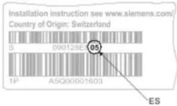
Figure 1: Example of a packaging label with details of the product version
Product version on the product label and the type plate
Details of the product version can be found after the device order number:

Figure 2: Example of a product label with details of the product version
3.1.3 Sensory
The radio fire detector has optical and thermal sensors. The radio fire detector can be parameterized as a smoke detector or a heat detector.

Figure 3: Fire detector structure
1 Heat sensors
2 Backward scatterer
3 Forward scatterer
4 Labyrinth
The radio fire detector has a sophisticated opto-electronic measuring chamber with two optical transmitters, an optical receiver, and two thermal sensors.
The transmitters illuminate the smoke particles from different angles. One sensor acts as forward scatterer, the other as backward scatterer. The scattered light then hits the receiver (photo diode) and generates a measurable electric signal.
The combination of a forward and backward scatterer facilitates an optimum detection and the differentiation of light and dark particles, which leads to a homogenous response behavior and optimizes the differentiation of wanted signals and deceptive phenomena.
3.2 Power supply
The battery pack BAT3.6-10 supplies the radio devices with power. The battery pack consists of lithium batteries plus a battery cable and a battery connector.
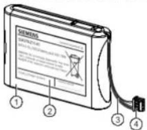
Figure 4: Battery pack BAT3.6-10
1 Battery pack consisting of:
• 4 lithium batteries for normal operation
• 1 lithium battery as a spare in the case of 'Battery low' operation
2 Label with area for filling in the commissioning date
3 Battery cable
4 Battery connector with protection against polarity reversal
• In normal operation: Can be used for the service life stated
• In 'Battery low' operation: subject to reduced operating life
- Connections cannot be reversed thanks to battery connector with protection against polarity reversal
3.3 Function
3.3.1 Parameter sets
The detection behavior of the detectors is influenced by the parameter sets, so that it can be specifically adjusted to the fire phenomena and environmental conditions to be expected in the environment to be monitored.
The parameter sets for smoke and heat detection are programmed in the detectors. During commissioning, the optimum parameter set must be selected for the conditions at the place of installation. This is carried out using the control panel.
3.3.2 Danger levels
The detector's signal processing efficiently distinguishes between fire events and deceptive phenomena. The basis for reaching a danger level is not only given by measured values exceeding a 'response threshold'; moreover, the smoke density progression is observed over a longer period of time and assessed by the algorithms.
Fire detectors can transmit the following danger levels to the control panel:
| Danger level | Meaning | Comment |
| 0 | No danger | Normal condition |
| 1 | Check the situation. | A different parameter set should potentially be selected (inappropriate application) |
| 2 | Warning | Possible danger |
| 3 | Alarm | Fire |
The evaluation of the danger level and the decisions to be taken (e.g., activation of remote transmission) are configured in the control panel.
3.3.4 Internal alarm indicator
The internal alarm indicator's LED has two colors and shows the operating condition of the radio fire detector.
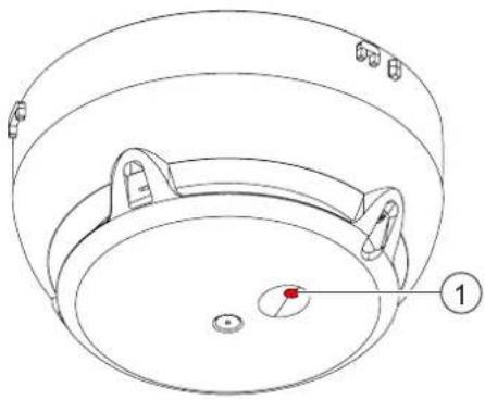
1 Internal alarm indicator
The table below describes the flashing behavior of the internal alarm indicator in the radio fire detector FDOOT271-O:

Several flashing patterns are available for normal operation. The flashing pattern is selected using the panel configuration program.
| Operating condition Flashing | mode | Graphic | |
| Alarm | IAI flashes red once a second |  | |
| Alarm in test mode | IAI flashes green twice every four seconds and red every second in-between |  | |
| Fault There is an error. | IAI flashes red four times every second |  | |
| Commissioning | The radio fire detector has not yet been logged on to a radio gatewayAndThe radio fire detector is not mounted on a detector base.AndThere is no contact with the radio network. | IAI flashes red once every two seconds |  |
| The radio fire detector has already been logged on to a radio gatewayAndThe radio fire detector is not mounted on a detector base.AndThere is no contact with the radio network. | IAI flashes green once every two seconds | ||
| The radio fire detector is mounted on the base but has not yet been logged on to the radio network. | IAI flashes green twice every two seconds | ||
| Normal Configuration 1 | IAI flashes green once every 30 seconds | ||
| Configuration 2 IAI off | |||
| Test | IAI flashes green twice every four seconds | ||
| New battery | IAI lights up once for five seconds | ||
| Battery is flat IAI off | |||

Several operating conditions may be indicated at the same time. This may lead to the flashing patterns overlapping one another. The red LED indicator has priority over the green LED indicator.
Flashing patterns with a higher frequency will overlap those with a lower frequency, which means that the latter may no longer be discernible.

Not all fire control panels support the flashing patterns described.
Please also observe the documentation for your fire detection system.
3.3.5 Renovation mode
Renovation mode is set using the control panel.
Renovation mode can be used under the following conditions:
- If there is a large amount of dust in the air around the radio fire detector temporarily
- If there are aerosols in the air around the radio fire detector temporarily. The radio fire detector does not issue alarms in renovation mode until a temperature of 80°C has been exceeded for 20 seconds.
You will find more detailed information in the fire detection system documentation.
3.3.6 Test mode
In test mode the radio fire detectors react faster and with a higher sensitivity level. For testing purposes, the radio fire detectors can be set to test mode using the control panel or the FXS2061-O Wireless diagnostic tool.
The following tests can be performed:
• Test of optical detector function using test gas
• Test of heat detector function using hot air
You will find more detailed information in the fire detection system documentation.
3.3.7 Interface to service devices
The fire control panel or the software FXS2061-O Wireless diagnostic tool is used to read out and set the parameter sets.
3.4 Mechanical setup
A mounted detector base FDB271 is required to mount the detector.
Once the detector is ready for use, twist it onto the detector base either manually
or using the detector exchanger
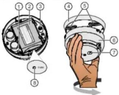
Figure 5: Mechanical setup
1 Battery connector
2 Battery pack
3 Switch
4 Detector base
5 Fixing screws
6 Detector
7 Internal alarm indicator
8 'new' button
See also
Accessories [→ 23]
25 Accessories
3.5.2 Detector base FDB271

• For installing radio fire detectors
• Directly attached to the mounting surface
• Fastened with two screws
- Compatible with:
- Radio fire detector FDOOT271-0
• Order number: S54319-F12-A1
3.5.3 Detector locking device FDBZ293

• For protection against theft
- Compatible with:
- Radio fire detector FDOOT271-0
• Order number: A5Q00005035
3.5.4 Designation plate FDBZ291

• To identify the location
- Compatible with:
- Detector base FDB271
• Order number: A5Q00002621
0.55 Detector dust on ED7004
4 Planning
4.1 Ambient features
In selecting the optimum parameter set, the following factors must be taken into account:
• Risk of damage to persons
• Value concentration
- Room geometry
• Deceptive phenomena
- Risk of fire
• Critical fire size
Risk of damage to persons
People's lives are severely at risk in venues such as concert halls, nursing homes, and hospitals. The risk of damage to persons is therefore very high in such places. In canteen kitchens the situation is different. Few people work in such facilities and are able to save themselves in the event of timely alarms. The risk of damage to persons is thus rather low in this case.
Value concentration
Irreplaceable cultural assets are often on display in museums. Computer centers house servers with large data volumes. The concentration of valuable items is rather high. In a normal hotel room the concentration of valuable items must be classified as low.
Room geometry
High ceilings, complex room shapes or well-ventilated rooms have a complex room geometry. This aggravates early fire detection, as it is difficult for the fire phenomenon to reach the fire detector. An office room with normal ceiling height has a simple room geometry.
Decentive phenomena
Critical fire size
When a waste paper basket in a metal-processing facility catches fire, the consequential damage is usually rather low. Here we are talking about a critical, medium fire size that can still be tolerated. The situation is completely different in pharmaceutical production facilities where even the lowest smoke concentration may impair the process and where combustible materials are processed. Even the smallest fire must be detected immediately. Therefore, we need to define what is termed a small admissible critical fire size.
4.2 Parameter sets for FDOOT271-O
4.2.1 Sensor mode 0 'Neural fire detector'
4.2.1.1 Description
(Parameter set numbers in brackets)
Robust (0)/(2):
The priority of the 'Robust' parameter set is to a robust response. It is thus particularly suited to application in rooms where deceptive phenomena such as cigarette smoke or dust can be expected. The 'Robust (2)' parameter set is suitable for higher rooms.
Suppression (5):
Thanks to its very robust behavior, the 'Suppression' parameter set is particularly suitable for rooms where deceptive phenomena such as cigarette smoke or exhaust fumes can be expected. It reacts in a very robust way to the deceptive phenomenon vapor.
Fast Response (6):
This parameter set reacts in a fast and highly sensitive manner. It is thus especially suited for rooms without deceptive phenomena, where the priority is on detecting the fire as early as possible.
4.2.1.2 Use
| No. | Name Risk of damage | to persons | Concentration of valuable items | Room geometry | Deceptive phenomena | Risk of fire Critical fire size | |
| small... large | low... high | simple... complex | few... many | small... large | small... medium | ||
| 0 | Robust | ||||||
| 2 | Robust | ||||||
| 5 | Suppression | ||||||
| 6 | Fast Response | ||||||
4.2.1.3 Specification
The following table displays the properties and fields of application of the parameter sets of radio fire detector FDOOT271-O in sensor mode 0.
| No. | Name | Optical | Thermal | ||||
| Typ. Response time from - typ. - to | Sensitivity, open fire | Sensitivity, smoldering fire | Static activation temperature | Differential activation temperature1 | Differential activation possible from: | ||
| [A] | [%m] | [%m] | [°C] | ΔT [K] | [°C] | ||
| 0 | Robust | 80 | 3.2 | 11.4 | 80 | 29 | 30 |
| 2 | Robust | 80 | 3.2 | 11.4 | 80 | 29 | 30 |
| 5 | Suppression | 90 - 160 - 780 | 3.2 | 11.4 | 80 | 29 | 30 |
| 6 | Fast Response | 20 - 30 | 1.6 | 5.6 | 80 | 22 | 3 |
1 Applicable with fast temperature increases >10 K/min.
i
All parameter sets comply with standards EN 54-7 and CEA 4021.
4.2.2 Sensor mode 1 'Heat detector'
4.2.2.1 Description
This sensor mode is especially suited for applications where the detector should only react thermally.
The heat detector FDOOT271-O has the following parameter sets:
A1R(1)
A1S (3)
4.2.2.2 Specification
| No. | Name | Operating temperature typ. / max. | Static activation temperature1 | Differential activation temperature2 | Differential activation possible from: |
| [°C] | [°C] | ΔT [K] | [°C] | ||
| 1 | A1R60 °C rate of rise | 25 / 50 | 60 | 25 | 3 |
| 3 | A1S60 °C maximum | 25 / 50 | 60 | - | - |
1 Applicable with slow temperature increases <1 K/min.
2 Applicable with fast temperature increases of >10 K/min. When there is a slow temperature increase of <10 K/min, this value rises by a few degrees.
i
Both parameter sets meet the criteria of standard EN 54-5.
4.2.3 Sensor mode 2 'Smoke detector'
4.2.3.1 Description
This sensor mode should be selected if fast temperature changes that are not caused by fire may occur (e.g., in the case of radiant heaters, hot engines). In this sensor mode the detector only reacts optically; this is comparable with a wide-spectrum smoke detector. However, because it has a second optical sensor, it reveals a more balanced response behavior in relation to the different types of fire.
Universal (1):
With 'Universal' the sensitivity and response time to aerosols are between 'Robust'
4.2.3.2 Use
| No. | Name Risk of damage to persons | Concentration of valuable items | Room geometry | Deceptive phenomena | Risk of fire Critical fire size | |
| small... large | low... high | simple... complex | few... many | small... large | small... medium | |
| 1 Universal |  |  |  |  |  | |
| 2 Robust |  |  |  |  |  | |
| 3 Sensitive |  |  |  |  |  | |
4.2.3.3 Specification
| No. Name | Response time [s] | Sensitivity | open fire/smoldering fire [%/m] |
| 1 Universal | 50 2.3 / 8 | ||
| 2 Robust | 80 2.3 / 8 | ||
| 3 Sensitive | 30 1.6 / 5.6 |

All parameter sets meet the criteria of standard EN 54-7.
4.3 Application examples
Please contact your system manufacturer for application recommendations, such as choosing the detector type and its settings for various applications.
5 Mounting / Installation
5.1 Required space
- Upon insertion of the detector, the detector base is stressed by compression, tension and torsion. The fixing must thus be designed accordingly.
• Detector bases must be placed flat on the ceiling. - Avoid mounting on steps, concrete ribs, etc.
- When selecting the installation position, take into account any structures that may impair radio reception.
5.2 Detector base FDB271
The detector base must be securely connected to the substructure.
Screw the detector base securely onto the substructure using two screws.

5.3 Mounting radio fire detector FDOOT271-O
i
The action of inserting the radio fire detector into the detector base activates it; the detector then logs on to other radio devices immediately. Therefore, start from the radio gateway and work outwards to install the individual radio fire detectors.
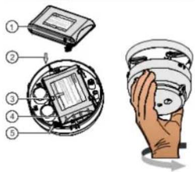
Figure 7: Mounting the radio fire detector
1 Battery pack BAT3.6-10 1
2 Inserting the battery pack
3 Holder
4 Battery cable
5 Battery connector
- Install the accessories you require.
- Label the new battery pack (1) with the current date.
- Connect the battery connector (5) of the new battery pack.
- Insert the new battery pack (1), paying attention to the position of the battery cable (arrows at 4).
-
Make sure that the holder (3) latches into place correctly.
When the battery connector is connected, the internal alarm indicator lights up red for 5 seconds.
After a further 10 seconds, the radio fire detector signals that it is not installed on the detector base and the internal alarm indicator flashes. If it flashes red, this indicates the factory settings. If it flashes green, this indicates that the radio fire detector has already been logged on to a radio gateway.
If this does not happen, this means the battery pack is defective and must not be used. -
Insert the radio fire detector into the detector base.
The internal alarm indicator flashes green and the radio fire detector is loaned on to the radio gateway.
If the process of logging on to the radio gateway is successful, the internal alarm indicator stops flashing.
The radio fire detector is now installed and is ready for commissioning.
See also
Internal alarm indicator [→ 20]
Internal alarm indicator [→ 20]
5.4 Detector locking device FDBZ293
The detector can be protected against theft with the detector locking device FDBZ293.

Figure 8: Mounting of detector locking device FD62293
1 Detector base
4 Detector
2 Set screw with a hexagon socket
5 Allen key
5.5 Designation plate FDBZ291
Designation plate FDBZ291 is used to assign a location address to the detector.
- Label the designation plate.
- Slide the designation plate into the detector base from the side.

Figure 9: Installing the designation plate
1 Designation plate 2 Detector base
6 Commissioning
When the battery connector is connected, the radio fire detector FDOOT271-O is activated. Once inserted into the detector base, the radio fire detector automatically looks for radio devices within range in the vicinity and automatically integrates itself into the radio network.
i
Insert the battery packs into the devices at the location where they are going to be used just before commissioning the fire detection installation.
The device is commissioned via the control panel. The exact procedure is described in the control panel documentation.
Conduct a performance check once commissioning is complete.
You will find additional information in the following documents:
Document A6V10425603
See also
Applicable documents [→ 7]
7 Maintenance / Repair
Check the detector on a regular basis, but at least once a year.
To do this, look for/check the following and resolve any problems you identify:
• Mechanical damage
- Soiling
- Correct fastening
• Detector function by means of test activation
7.1 Status query
The query is issued from the control panel, via the radio gateway.
The following queries may be issued:
- Danger level
- Detector fault
- Radio status
Depending on the authorization level of the user and the control panel type, the following actions can be performed:
• Device test (Go/No Go or detailed by status polling)
• Activation of a test alarm
- Reading out the identification number, customer text and measure text
- Localizing and setting the parameters of the detector
• Switching off the detector
See also
Diagnosis levels [→ 19]
Internal alarm indicator [→ 20]
7.2 Performance check
The selftest automatically subjects the detectors to an extensive electrical
7.5 Establishing factory settings
All existing settings are deleted and reset to the factory settings.

Figure 10: Establishing factory settings
1 Internal alarm indicator
2 'new' opening with button
To create the factory settings on the radio fire detector, proceed as follows:
The radio fire detector is being supplied with power.
▷ You have a slim pen or pencil to hand.
1. Remove the radio fire detector from the detector base.
2. Wait until the internal alarm indicator (1) flashes green (2-second interval).
The detector is 'out of base'.
3. Press the pen or pencil into the 'new' opening (2) for 5 seconds.
The internal alarm indicator flashes red (2-second interval).
The radio fire detector is set to the factory settings.
7.6 Basic principles for replacing the battery pack

WARNING
Risk of explosion due to fire or short-circuit, even if the battery pack is discharged Injuries caused by flying parts
- To prevent the connection wires short-circuiting, insulate the connections and stick the battery cable to the battery pack.
• Do not allow the battery pack to come into contact with water.
• Do not extinguish a burning battery pack with water.
• Do not recharge the battery pack.
• Do not damage or dismantle the battery pack.
• Do not heat the battery pack to more than 100 °C.

WARNING
Disposing of damaged or leaky battery packs
Lithium can burn the skin and produce toxic vapors.
- Avoid direct contact with the body. Wear appropriate protective clothing (safety gloves, safety goggles, etc.). Use appropriate means of transportation to move damaged batteries around.
- Do not breathe in vapors. Ensure that there is sufficient ventilation.
Always observe the following information:
- When the control panel issues the message 'Battery low', replace the battery pack.
• Use the control panel to identify the location of the radio device.
• Only use battery pack BAT3.6-10. - The battery pack must be new and free from damage. The battery cable is attached to the battery pack with an additional label
7.7 Replacing the battery pack
• Do not interrupt the power supply for longer than 2 minutes.
- Do not interrupt the power supply to multiple radio devices simultaneously. Replace the battery pack for one radio device as described below before replacing the battery pack for the next radio device. This will prevent mix-ups and will ensure the devices can be reintegrated into the radio cell without any problems.

Maintenance / Repair
Replacing the battery pack
- Remove the detector from the detector base.
- Wait until the internal alarm indicator flashes green (interval: 2 seconds).
The detector is 'out of base'. - Push the holder (4) to the side and remove the battery pack (1).
- Release the battery connector (6).
- Dispose of the old battery pack.
- Label the new battery pack with the current date.
- Connect the battery connector (6) of the new battery pack.
- Insert the new battery pack, paying attention to the position of the battery cable (arrows at 5).
-
Make sure that the holder (4) latches into place correctly.
When the battery connector is connected, the internal alarm indicator lights
After a further 10 seconds, the detector signals that it is not installed on the detector base and the internal alarm indicator flashes green (flashing pattern number 3).
If this does not happen, this means the battery pack is defective and must not be used. -
Insert the detector into the detector base.
The internal alarm indicator flashes green (flashing pattern number 4) and the detector is logged on to the radio gateway.
If the process of logging on to the radio gateway is successful, the internal alarm indicator stops flashing.
-
Following the successful logon, replace the battery pack of the next radio device.
-
Check the status display on the radio gateway or the 'Device localization error' display on the control panel.
- If there is a 'Device localization error' message on the radio gateway or the
8 Specifications
8.1 Technical data
You will find information on approvals, CE marking, and the relevant EU directives for this device (these devices) in the following document(s); see 'Applicable documents' chapter:
- Document A6V10431682
Device characteristics
| Response sensitivity | 2.3...12 %/m |
| Compensation speed | ≤1/45 voltage increase for detection/h |
| Detector diagnosis | With Wireless diagnostic tool or connected fire control panel |
Radio
| Sending/receiving aerials | Dual band aerial |
| Frequency range | 433.05...434.79 MHz in band 44b and 45b1868...870 MHz in band 48, 49, 50, 54b, and 56b1 |
| Channel grid | 50 kHz |
| Number of channels | 27 in 868-MHz band20 in 433-MHz band |
| Transmitting power | ≤10 mW ERP in band 44b, 45b, and 491Type 10 (max. ≤25) mW ERP in band 48, 50, 54b, and 56b1 |
| Range | See document 'A6V10425603' |
2013/752/EU: according Official Journal of the European Union, COMMISSION IMPLEMENTING DECISION of 11 December 2013 according to December 2008 (TJVEC) on harmonisation of the radio spectrum for
Specifications
Technical data
8
Ambient conditions
| Operating temperature: | -10...+55 °C |
| Storage temperature | -30...+75 °C |
| Air humidity | ≤95 % rel. |
| Protection category (IEC 60529): | IP44 |
| Electromagnetic compatibility: | |
| 100 kHz...2.5 GHz | 30 V/m |
| Permissible wind speed: | Max. 5 m/s |
Mechanical data
| Weight without accessories | 0.132 kg |
| Housing material | Acrylonitrile-butadiene-styrene (ABS) |
| Color | -RAL 9010 pure white |
Standards
| European standards | EN 54-11 |
| EN 54-25 | |
| EN 300220-2 | |
| EN 301489-3 | |
| EN 60950-1 |
8.2 Dimensions
Radio fire detector FDOOT271-O with detector base FDB271

8.3 Environmental compatibility and disposal

This equipment is manufactured using materials and procedures which comply with current environmental protection standards as best as possible. More specifically, the following measures have been undertaken:
• Use of reusable materials
• Use of halogen-free plastics
• Electronic parts and synthetic materials can be separated
Larger plastic parts are labeled according to ISO 11469 and ISO 1043.
The plastics can be separated and recycled on this basis.

Electronic parts and batteries must not be disposed of with domestic waste.
• Take electronic parts and batteries to local collection points or recycling centers.
- Contact local authorities for more information.
- Observe national requirements for disposing of electronic parts and batteries.
Glossary
Factory setting
Basic settings present at the time of delivery
Radio device
Any device that the radio gateway monitors
Radio network
Within a radio cell, bidirectional radio connections are established between the radio devices. Together with the radio gateway connections, these create a radio network.
Index
A
Approvals 42
B
Battery pack
Description.... 23
Replacing 40
Replacing the battery pack 39
C
CE marking 42
Control panel 35
D
Danger level
Signal processing of the detector 19
Detection behavior of the detector
Parameter set 19
Diagnosis levels 19
Disposal 45
Documentation for fire detection system 21
Download center
URL 8
E
Environmental compatibility 45
ES
Product version 16
EU directives 42
F
Flashing mode
Internal alarm indicator 20
Flashing pattern
Configuration 20
Internal alarm indicator 20
|
Intended use 5
O
Original language 6
P
Packaging label
Product version.... 16
Parameter set
Detection behavior of the detector 19
Product label
Product version 16
R
Recycling 45
S
Signal processing of the detector
Danger level 19
Source language 6
Standards 43
T
Type plate
Product version 16
Issued by
Siemens Switzerland Ltd
Building Technologies Division
International Headquarters
Gubelstrasse 22
CH-6301 Zug
+41 41-724 24 24
www.siemens.com/buildingtechnologies
© Siemens Switzerland Ltd, 2014
Technical specifications and availability subject to change without notice.


- SIEMENS
- FDOOT271-O
- RADIO FIRE DETECTOR
- TECHNICAL MANUAL
- LEGAL NOTICE
- TABLE OF CONTENTS
- 1 ABOUT THIS DOCUMENT
- GOAL AND PURPOSE
- INTENDED USE
- TARGET GROUPS
- SOURCE LANGUAGE AND REFERENCE DOCUMENT
- DOCUMENT IDENTIFICATION
- ABOUT THIS DOCUMENT
- APPLICABLE DOCUMENTS
- CONVENTIONS FOR TEXT MARKING MARKUP
- SUPPLEMENTARY INFORMATION AND TIPS
- 1.1 APPLICABLE DOCUMENTS
- 1.2 DOWNLOAD CENTER
- 1.3 TECHNICAL TERMS AND ABBREVIATIONS
- 1.4 HISTORY OF CHANGES
- 2 SAFETY
- 2.1 SAFETY INSTRUCTIONS
- SYMBOL FOR DANGER
- ADDITIONAL DANGER SYMBOLS
- SIGNAL WORD
- HOW RISK OF INJURY IS PRESENTED
- WARNING
- NATURE AND ORIGIN OF THE DANGER
- HOW POSSIBLE DAMAGE TO PROPERTY IS PRESENTED
- NOTICE
- 2.2 SAFETY REGULATIONS FOR THE METHOD OF OPERATION
- NATIONAL STANDARDS, REGULATIONS AND LEGISLATION
- ELECTRICAL INSTALLATIONS
- ELECTRICAL VOLTAGE
- MOUNTING, INSTALLATION, COMMISSIONING AND MAINTENANCE
- TESTING THE PRODUCT OPERABILITY
- MODIFICATIONS TO THE SYSTEM DESIGN AND THE PRODUCTS
- MODULES AND SPARE PARTS
- 2.3 STANDARDS AND DIRECTIVES COMPLIED WITH
- 2.4 RELEASE NOTES
- LIMITED OR NON-EXISTENT FIRE DETECTION
- INCORRECT PLANNING AND/OR CONFIGURATION
- 3 STRUCTURE AND FUNCTION
- 3.1 OVERVIEW
- PROPERTIES
- 3.1.2 PRODUCT VERSION ES
- PRODUCT VERSION ON THE PACKAGING LABEL
- PRODUCT VERSION ON THE PRODUCT LABEL AND THE TYPE PLATE
- 3.1.3 SENSORY
- 3.2 POWER SUPPLY
- 3.3 FUNCTION
- 3.3.1 PARAMETER SETS
- 3.3.2 DANGER LEVELS
- 3.3.4 INTERNAL ALARM INDICATOR
- 3.3.5 RENOVATION MODE
- 3.3.6 TEST MODE
- 3.3.7 INTERFACE TO SERVICE DEVICES
- 3.4 MECHANICAL SETUP
- SEE ALSO
- 25 ACCESSORIES
- 3.5.2 DETECTOR BASE FDB271
- 3.5.3 DETECTOR LOCKING DEVICE FDBZ293
- 3.5.4 DESIGNATION PLATE FDBZ291
- 0.55 DETECTOR DUST ON ED7004
- 4 PLANNING
- 4.1 AMBIENT FEATURES
- RISK OF DAMAGE TO PERSONS
- VALUE CONCENTRATION
- ROOM GEOMETRY
- CRITICAL FIRE SIZE
- 4.2 PARAMETER SETS FOR FDOOT271-O
- 4.2.1 SENSOR MODE 0 'NEURAL FIRE DETECTOR
- 4.2.1.1 DESCRIPTION
- ROBUST (0)/(2)
- SUPPRESSION (5)
- FAST RESPONSE (6)
- 4.2.1.3 SPECIFICATION
- 4.2.2 SENSOR MODE 1 'HEAT DETECTOR
- 4.2.2.1 DESCRIPTION
- 4.2.2.2 SPECIFICATION
- 4.2.3 SENSOR MODE 2 'SMOKE DETECTOR
- 4.2.3.1 DESCRIPTION
- UNIVERSAL (1)
- 4.2.3.2 USE
- 4.2.3.3 SPECIFICATION
- 4.3 APPLICATION EXAMPLES
- 5 MOUNTING / INSTALLATION
- 5.1 REQUIRED SPACE
- 5.2 DETECTOR BASE FDB271
- 5.3 MOUNTING RADIO FIRE DETECTOR FDOOT271-O
- 5.4 DETECTOR LOCKING DEVICE FDBZ293
- 5.5 DESIGNATION PLATE FDBZ291
- 6 COMMISSIONING
- 7 MAINTENANCE / REPAIR
- 7.1 STATUS QUERY
- 7.2 PERFORMANCE CHECK
- 7.5 ESTABLISHING FACTORY SETTINGS
- 7.6 BASIC PRINCIPLES FOR REPLACING THE BATTERY PACK
- 7.7 REPLACING THE BATTERY PACK
- MAINTENANCE / REPAIR
- REPLACING THE BATTERY PACK
- 8 SPECIFICATIONS
- 8.1 TECHNICAL DATA
- 8.2 DIMENSIONS
- 8.3 ENVIRONMENTAL COMPATIBILITY AND DISPOSAL
- GLOSSARY
- FACTORY SETTING
- RADIO DEVICE
- RADIO NETWORK
- INDEX
- A
- B
- C
- D
- E
- F
- O
- P
- R
- S
- T
Marke : BOSCH
Modell : FDOOT271-O
Kategorie : Rauchmelder