
AD1200Pro - Beleuchtung GODOX - Kostenlose Bedienungsanleitung
Finden Sie kostenlos die Bedienungsanleitung des Geräts AD1200Pro GODOX als PDF.


| Produkttyp | Blitzkit (Blitzkopf + Netzteil) |
| Modell | AD1200Pro |
| Marke | Godox |
| Kategorie | Beleuchtung (Studio-Blitz) |
| Leistung | 1200 Ws |
| Blitzmodi | TTL, Manuell (M), Multi (Stroboskop) |
| Leistungsbereich | 1/256 bis 1/1 in 81 Schritten |
| Blitzdauer (t₁) | 1/220 bis 1/10860 Sekunden |
| Leitzahl (ISO 100, 1/1) | 124 m (mit hocheffizientem Standardreflektor) |
| Farbtemperatur | 5600 ± 200 K |
| Stabiler Farbtemperaturmodus | ±75 K über gesamten Leistungsbereich |
| Modellierlampe | 40 W LED, Helligkeit einstellbar (1%–100% oder proportional) |
| Hochgeschwindigkeitssynchronisation | Bis 1/8000 s |
| Drahtlossteuerung | 2,4-GHz-X-System, Reichweite ca. 100 m, 32 Kanäle, 5 Gruppen (A–E), Wireless-ID (01–99) |
| Kompatible Kamerasysteme (Slave) | Canon, Nikon, Sony, Olympus, Panasonic, Fujifilm, Pentax |
| Blitzbelichtungskorrektur (FEC) | Ja, am Sender einstellbar |
| Sync-Anschluss | 3,5-mm-Klinkenstecker |
| Stromversorgung | Lithium-Ionen-Akku 36 V / 5200 mAh |
| Vollblitzanzahl (Akku) | Ca. 500 |
| Blitzbereitschaftszeit | Ca. 0,01–2 s |
| Akku-Ladezeit | Ca. 3 h mit mitgeliefertem Ladegerät |
| Abmessungen Blitzkopf (mit Reflektor) | 12,5 × 23 × 20 cm |
| Abmessungen Netzteil | 23,5 × 14,5 × 26 cm |
| Nettogewicht (Kit) | 8,25 kg |
| Zubehör im Lieferumfang | Netzteil, Blitzkopf, Lithium-Akku, Ladegerät, Netzkabel, Reflektor, Glasschutzabdeckung, Transporttasche, Bedienungsanleitung |
Häufig gestellte Fragen - AD1200Pro GODOX
Benutzerfragen zu AD1200Pro GODOX
0 Frage zu diesem Gerät. Beantworten Sie die, die Sie kennen, oder stellen Sie Ihre eigene.
Eine neue Frage zu diesem Gerät stellen
Laden Sie die Anleitung für Ihr Beleuchtung kostenlos im PDF-Format! Finden Sie Ihr Handbuch AD1200Pro - GODOX und nehmen Sie Ihr elektronisches Gerät wieder in die Hand. Auf dieser Seite sind alle Dokumente veröffentlicht, die für die Verwendung Ihres Geräts notwendig sind. AD1200Pro von der Marke GODOX.
BEDIENUNGSANLEITUNG AD1200Pro GODOX
QC PASS
Godox
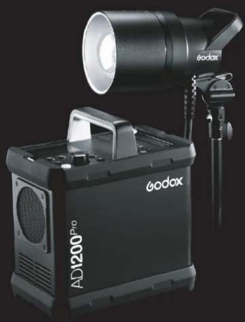
natural_image
Exterior view of a black and white Kodax AD1200 Pro lighting device with adjustable lens (no text or symbols on the device body)
Official Account
GODOX Photo Equipment Co., Ltd.
Add: Building 2, Yaochuan Industrial Zone, Tangwei Community. Fuhai Street, Bao'an District, Shenzhen518103, China Tel: +86-755-29609320(8062) Fax: +86-755-25723423 Email: godox@igodox.com
www.godox.com
Made in China | 705-AD12P0-08
UK CA F C CE
AD1200Pro Kit
1200Ws TTL Power Pack Kit
INSTRUCTION MANUAL
Foreword
Before using this product
Please read this user manual carefully in order to ensure your safety and the proper operation of this product. Keep for future reference.
Thank you for purchasing a GODOX product.
1200Ws TTL Power Pack AD1200Pro Kit includes a flash head and power pack. When using Godox 2.4G wireless X system off camera, AD1200pro Kit can be triggered by XPro, X1 and X2 series flash trigger in TTL/M/Multi mode, etc. AD1200Pro Kit can also use in combination with Godox TTL camera flashes, TTL outdoor flashes, TTL studio flashes, etc. With this AD1200Pro power pack kit, your shooting will become simpler. You can easily achieve a correct flash exposure even in complex light-changing environments.
AD1200Pro Kit offers high quality light for outdoor and live shooting with strong power and large capacity lithium battery pack. The powerful and portable AD1200Pro Kit meets the demands of freelance commercial photographers, photojournalists, wedding and beach portraiture shooters, event and backpack photographers, photograph enthusiasts, etc. The AD1200Pro Kit offers:
- Stable color temperature mode: color temperature changes within 5600±75K over the entire power range (stable color temperature mode).
- LED modeling lamp: 40W LED modeling lamp whose light brightness can be freely adjusted.
- Compatible wireless TTL system: with built-in Godox 2.4G wireless X system, AD1200Pro Kit is compatible with Canon, Nikon, Sony, FUJIFILM, Olympus and Panasonic TTL autoflash system. AD1200Pro Kit has two 3.5mm sync cord jack to achieve various sync triggering mode.
- Precise power output: power adjusts from full power 1/256 to 1/1 in 81 steps.
- Advanced functions: 1/8000s high-speed sync flash, multi flash, high-speed sync triggering, etc.
- Portable flash head: with convenient and portable lighting.
- Dot-matrix LCD panel: with clear and convenient operation.
- Wide-range accessories: adopted Bowens-mount with abundant accessories.

Warning
Always keep this product dry. Do not use in rain or in damp conditions.
Do not disassemble. Should repairs become necessary, this product must be sent to an authorized maintenance center.
Keep out of reach of children.
Stop using this product if it breaks open due to extrusion, falling or strong hit. Otherwise, electric shock may occur if you touch the electronic parts inside it.
Do not fire the flash directly into the eyes (especially those of babies) within short distances. Otherwise visual impairment may occur.
Do not use the flash unit in the presence of flammable gases, chemicals and other similar materials. In certain circumstance, these materials may be sensitive to the strong light emitting from this flash unit and fire or electromagnetic interference may result.
Do not leave or store the flash unit if the ambient temperature reads over 50°C. Otherwise the electronic parts may be damaged.
⚠️ Turn off the flash unit immediately in the event of malfunction.
CAUTION: Hot parts! Do not touch the inside of the flash head when the LED light and flash are working. When replacing the flash accessory, please turn off the flash first to cold cut.
Contents
01 Foreword
02 Warning
05 Name of Parts
Power Pack
Control Panel
LCD Panel
Lithium Battery
Flash Head
09 Included Accessories
09 Separately Sold Accessories
10 Installing Reflector (Other Accessories)
10 Attaching Flash Tube
11 Adjusting Handle
11 Battery
12 Power Management
12 Flash Head Connection
13 Wireless Flash Mode
13 Flash Mode—TTL Autoflash
14 Flash Mode—M: Manual Flash
16 Flash Mode—Multi: Stroboscopic Flash
17 Wireless Flash Shooting: Radio (2.4G) Transmission
Wireless Settings
Setting the Communication Channel
Setting the Communication Group
Wireless Flash Shooting
20 C.Fn: Setting Custom Functions
21 Modeling Lamp
21 Other Applications
Sync Triggering
22 Protection Function
23 Technical Data
24 Troubleshooting
24 Firmware Upgrade
24 Maintenance
Conventions used in this Manual
- This manual is based on the assumption that both the camera and camera flash's power switches are powered on.
• Reference page numbers are indicated by "p."
• The following alert symbols are used in this manual:
The Caution symbol indicates a warning to prevent shooting problem.
① The Note symbol gives supplemental information.
Name of Parts
Power Pack:
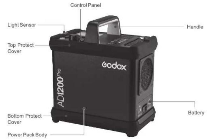
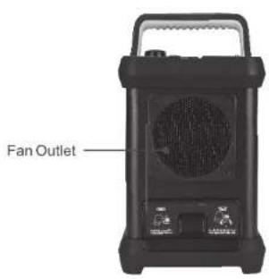
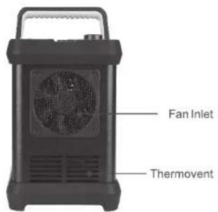
-05
Name of Parts
Control Panel:
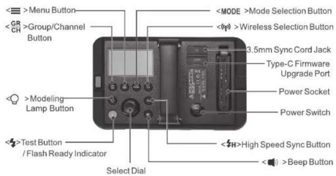
LCD Panel
(1) TTL Autoflash
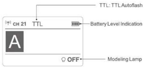
-06-
Name of Parts
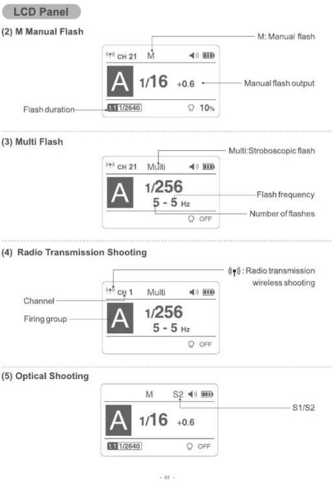
Name of Parts
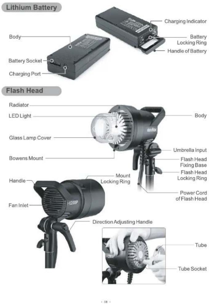
Included Accessories
- Power pack 2. Flash head
- Lithium battery
- Charger
- Power connection cord
- Reflector
- Glass protection cover
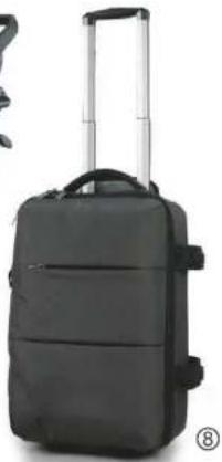
- Portable bag
- Instruction manual
⑥

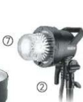
natural_image
Black suit case with handle and straps, no visible text or symbols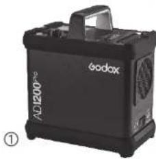
natural_image
Black and white photo of a Kodax 200® portable electronic device (no visible text or symbols on body)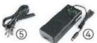
Separately Sold Accessories
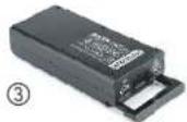
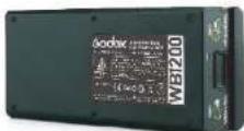
AD1200Pro Kit can separately purchase a WB1200 battery with smaller capacity and more portability. When using WB1200 battery, the full power pops of AD1200Pro Kit will be approx. 200.
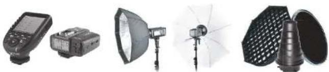
It can also be used in combination with the following accessories sold separately, so as to achieve best photography effects: Xpro/X1/X2 Wireless Flash Trigger, FT-16 Remote Control, Softbox, Beauty Dish, Fold up Umbrella, Snoots, Light Stand, etc.
natural_image
Product catalog image showing five different photography lighting equipment including a handheld device, studio lamp, umbrella, and conical frandescent (no text or labels visible)· 咚 ·
Installing Reflector (Other Accessories)

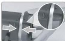
1 Press down the Lamp Cover Locking Ring.

2 Insert the reflector into the accessory mount and clock wise to lock it up.
Attaching Flash Tube
Install Flash Tube
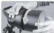
1 Remove the reflector or other accessories from the flash head.
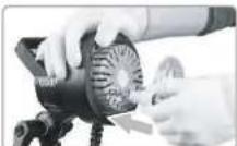
2 Match the flash tube in the Tube Socket. Push the flash tube in until it is securely seated into the socket.
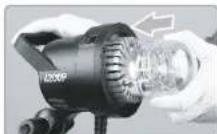
3 Install the glass protection cover.
Detach Flash Tube
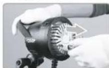
1 Pinch the flash tube holder with your thumb and forefinger and pull out the tube upwards.
-10-
Name of Parts
Adjusting Handle
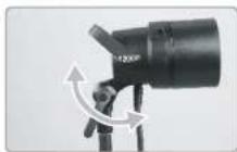
1 When the Direction Adjusting Handle is not pulled out, screw clockwise while unscrew anti clockwise.
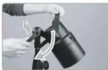
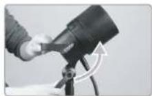
2 The Direction Adjusting Handle's rotation angle should be restrained from 0 to 240 degrees below the flash body. Please pull out the Direction Adjusting Handle, adjust the appropriate angle, and manipulate the step 1 before colliding with the flash body.
Battery
Features
-
This flash unit uses internationally recognized Li-ion polymer battery which has long runtime. The available charge-and-discharge times are over 500.
-
It is reliably safe. The inner circuit is against overcharge, overdischarge, overcurrent, and short circuit.
-
Take only 3 hours to fully charge the battery by using the included battery charger.
-
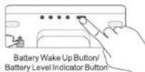
Wake up function: to protect the battery and extend battery's life, the battery will enter sleep mode if not used for about 30 days. As the battery in sleep mode cannot be used, please press the battery wake up button(battery level indicator button) or charge it with the charger before usage. Then, the battery will back to normal.
Cautions
Do not short circuit.
Do not expose to rain or immerse into water. This battery is not water proof.
Keep out of reach of children.
No over 24 hours' continuous charging.
▲ Store in dry, cool, ventilated places
Do not put aside or into fire.
▲ Dead batteries should be disposed according to local regulations.
▲ Please charge the battery to approx. 60% before being placed for long time. To extend the battery life, it is recommended to charge the battery every three months.
It is recommended to replace with a brand-new battery after over 500 charge-and-discharge times or three-year usage of battery.
Loading and Unloading the Battery Pack
Loading

1 Put the battery into the battery compartment.
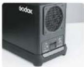
2 Push down the battery pack until it is locked.
-11
Unloading

1 Push up the Battery Locking Ring and the rod pop out.
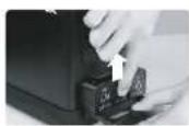
2 Hold upward the the Battery Locking Ring, and take the battery out.
Battery Level Indication
Attach the battery pack to the flash correctly. Be aware of the battery level by check the battery level indication on the LCD panel when using.
| Battery Level Indication on the LCD Panel (Indicating battery level and management of the whole flash system) | LED Battery Level Indication on the Battery (Indicating battery level and management of non-loaded battery) | Meaning/Percentage of Battery Level |
| 3 grids | 1 red grid +3 green grids | 75%~100% |
| 2 grids | 1 red grid +2 green grids | 50%~75% |
| 1 grid | 1 red grid +1 green grid | 25%~50% |
| Blank grid | 1 red grid | 3%~25% |
| Low battery and charging reminder | 2%: red light blinks1%: the indicator is off. | <2%The battery level is going to be used out immediately.And the flash will alarm for the 1 minute and auto power off in 3 minutes. Note: Please recharge the battery as soon as possible (within 10 days). Then, the battery can be used or be placed for long period. |
Note: The indications are almost the same except of grids shift.
Power Management
Long press the Power Switch for 1 seconds to control the on/off of the flash unit. Turn off the power pack if the flash unit will not be used for an extended period. This product has auto power off function. The flash will auto power off in 30 to 120 min. which is set on C.Fn-STANDBY.
Flash Head Connection
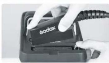
Insert the power cord plug of flash head into the power socket. Please insert the tail end of the plug into the slot firstly and insert the other end to finish installation. When taking the plug out, hold down the spring and pull out the plug upwards.
natural_image
Close-up of hands inserting a DODAX card into a device (no visible text or symbols)-12-
Wireless Flash Mode
AD1200Pro Kit can only be set as slave unit (receiver end). Press Wireless Selection Button to switch the two wireless modes: built-in wireless transmission and external wireless transmission.
Flash Mode — TTL Autoflash
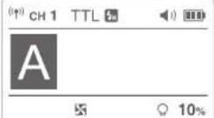
This flash has three flash modes: TTL, Manual (M), and Multi (Stroboscopic). In TTL mode, the camera and the flash will work together to calculate the correct exposure for the subject and the background.
* Press
TTL Mode
Press
High-Speed Sync
High Speed Sync (FP flash) enables the flash to synchronize with all camera shutter speeds. This is convenient when you want to use aperture priority for fill-flash portraits.
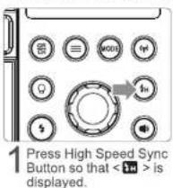
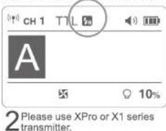
- If you set a shutter speed that is the same as or slower than the camera's maximum flash sync speed, < 70> will not be displayed in the viewfinder.
- With high-speed sync, the faster the shutter speed, the shorter the effective flash range.
- To return to normal flash, press <button again. Then <will disappear.
- Multi flash mode cannot be set in high-speed sync mode.
• Over-temperature protection may be activated after 100 consecutive high-speed sync flashes.
Flash Mode — M: Manual Flash
The flash output is adjustable from 1/1 full power to 1/256th power in 0.1 or 1 step increments. To obtain a correct flash exposure, use a hand-held flash meter to determine the required flash output.
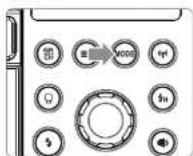
1 Press < MODE > button so that < M > is displayed.
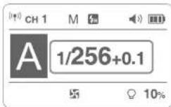
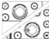
2 Turn the Select Dial or press down the Select Dial and turn it simultaneously to choose a desired flash output amount. Directly turn the Select Dial to add in 0.1 increment. Press down the Select Dial and turn it simultaneously to add in 0.1 increment.
3 Press < SET > button again to confirm the setting.
Optical S1 Secondary Unit Setting
In M manual flash mode, press <> button to enter C.FN-SLAVE to choose S1 function, so that this flash can function as an optic S1 secondary flash with optic sensor. With this function, the flash will fire synchronously when the main flash fires, the same effect as that by the use of radio triggers. This helps create multiple lighting effects.
Optical S2 Secondary Unit Setting
Press <> button to enter C.FN-SLAVE to choose S2 function, so that this flash can also function as an optic S2 secondary flash with optic sensor in M manual flash mode. This is useful when cameras have pre-flash function. With this function, the flash will ignore a single "preflash" from the main flash and will only fire in response to the second, actual flash from the main unit.
- S1 and S2 optical triggering is only available in M manual flash mode.
Flash Mode — M: Manual Flash
Display Flash Duration
Flash duration refers to the length of time that from flash's firing to reach the half peak at maximum. The half peak at maximum is usually expressed as t=0.5. In order to provide the photographer with more concrete data, this product adopts t=0.1. The difference between t=0.5 and t=0.1 is shown in the following picture.
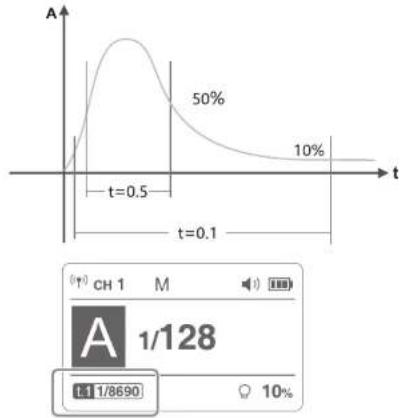
line
| t | A | |-------|-------| | 0.5 | 50% | | 0.1 | 10% |• The flash duration will only be displayed on the LCD panel in M mode.
Stable Color Temperature Function
When use this function, the color temperature changes within ±75K over the entire power range: enter MENU C.Fn-COLOR and set it as ON, which means the color temperature function is turned on. When adjusting the power output from high to low in M mode, Flash Ready Indicator will blink (the beeper will alarm for 1 minute). Now press the Test Button to discharge, and the flash can be used as normal.
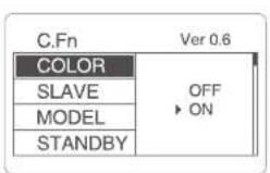
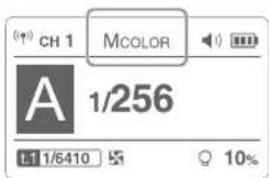
This function can only be supported in M non-high-speed mode.
Flash Mode — Multi: Stroboscopic Flash
With stroboscopic flash, a rapid series of flashes is fired. It can be used to capture a multiple images of a moving subject in a single photograph. You can set the firing frequency (number of flashes per sec. expressed as Hz), the number of flashes, and the flash output.
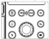
1 Press
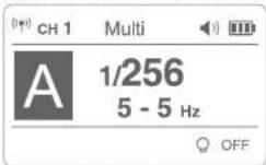
2 Turn the Select Dial to choose a desired flash output.
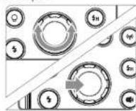
3 Set the flash frequency and flash times.
- Press
- Press
- After you finish the setting, press
Calculating the Shutter Speed
During stroboscopic flash, the shutter remains open until the firing stops. Use the formula below to calculate the shutter speed and set it with the camera.
Number of Flashes / Flash Frequency = Shutter Speed
For example, if the number of flashes is 10 and the firing frequency is 5 Hz, the shutter speed should be at least 2 seconds.
To avoid overheating and deteriorating the flash head, do not use stroboscopic flash more than 10 times in succession. After 10 times, allow the camera flash to rest for at least 15 minutes. If you try to use the stroboscopic flash more than 10 times in succession, the firing might stop automatically to protect the flash head. If this happens, allow at least 15 minutes' rest for the flash.
- Stroboscopic flash is most effective with a highly reflective subject against a dark background. - Using a tripod and a remote control is recommended.
- A flash output of 1/1 and 1/2 cannot be set for stroboscopic flash.
- Stroboscopic flash can be used with "buLb".
- If the number of flashes is displayed as “—”, the firing will continue until the shutter closes or the battery is exhausted. The number of flashes will be limited as shown by the following table
Maximum Stroboscopic Flashes:
| Flash Output\Hz | 1 | 2 | 3 | 4 | 5 | 6-7 | 8-9 | 10 | 11 | 12-14 | 15-19 | 20-50 | 60-100 |
| 1/4 | 7 | 6 | 5 | 4 | 4 | 3 | 3 | 2 | 2 | 2 | 2 | 2 | 2 |
| 1/8 | 14 | 14 | 12 | 10 | 8 | 6 | 5 | 4 | 4 | 4 | 4 | 4 | 4 |
| 1/16 | 30 | 30 | 30 | 20 | 20 | 20 | 10 | 8 | 8 | 8 | 8 | 8 | 8 |
| 1/32 | 60 | 60 | 60 | 50 | 50 | 40 | 30 | 20 | 20 | 20 | 18 | 16 | 12 |
| 1/64 | 90 | 90 | 90 | 80 | 80 | 70 | 60 | 50 | 40 | 40 | 35 | 30 | 20 |
| 1/128 | 100 | 100 | 100 | 100 | 100 | 90 | 80 | 70 | 70 | 60 | 50 | 40 | 40 |
| 1/256 | 100 | 100 | 100 | 100 | 100 | 90 | 80 | 70 | 70 | 60 | 50 | 40 | 40 |
Wireless Flash Shooting: Radio (2.4G) Transmission
AD1200Pro Kit adopts Godox 2.4G wireless X system, which has good compatibility with other products of our company.
As a slave unit, AD1200Pro Kit is automatically compatible with Canon E-TTL II, Nikon i-TTL, Sony, Olympus, Panasonic and FUJIFILM system according to the master unit.
*As a slave unit, AD1200Pro Kit can be controlled by the following master units: AD360II series, TT685 series, V860II series, V850II series, XPro series, X1T series, X2T series, TT600 series, TT350 series, etc.
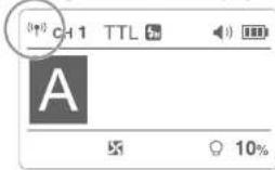
1. Wireless Settings
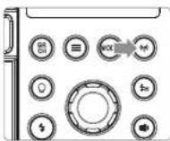
Press < (||)> Wireless Setting Button again until < (||)> is displayed on the panel.
2. Setting the Communication Channel
If there are other wireless flash systems nearby, you can change the channel IDs to prevent signal interference. The channel IDs of the master unit and the slave unit(s) must be set to the same.
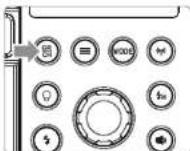
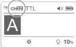
1 Long press the
2 Turn the Select Dial to choose a
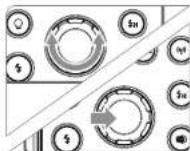
3 Press the
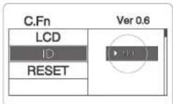
4 Wireless ID setting: press the MENU button to enter C.Fn-ID and choose from 01 to 99.
Wireless Flash Shooting: Radio (2.4G) Transmission
3. Setting the Communication Group
Short press the
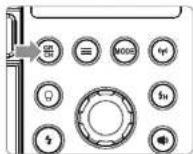
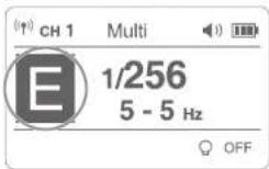
4. Wireless Flash Shooting
Positioning and Operation Range (Example of wireless flash shooting)
• Autoflash Shooting with One Slave Unit
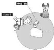
Transmission distance is about 100m
- Use master unit with wireless transmitting function as the transmitter end.
- Before shooting, perform a test flash and test shooting.
- The transmission distance might be shorter depending on the conditions such as positioning of slave units, the surrounding environment and whether conditions.
Wireless Flash Shooting: Radio (2.4G) Transmission
Wireless Multiple Flash Shooting
You can divide the slave units into two or three groups and perform TTL autoflash while changing the flash ratio (factor). In addition, you can set and shoot with a different flash mode for each firing group.
• Auto Shooting with Two Slave Groups

• Auto Shooting with Three Slave Groups
The Reason & Solution of Not Triggering in Godox 2.4G Wireless
- Disturbed by the 2.4G signal in outer environment (e.g. wireless base station, 2.4G wifi router, Bluetooth, etc.)
→ To adjust the channel CH setting on the flash trigger (add 10+ channels) and use the channel which is not disturbed. Or turn off the other 2.4G equipment in working. - Please make sure that whether the flash has finished its recycle or caught up with the continuous shooting speed or not (the flash ready indicator is lighten) and the flash is not under the state of over-heat protection or other abnormal situation. →Please downgrade the flash power output. If the flash is in TTL mode, please try to change it to M mode (a preflash is needed in TTL mode).
- Whether the distance between the flash trigger and the flash is too close or not →Please turn on the "close distance wireless mode" on the flash trigger (< 0.5m): X1 series: press the test button and hold on, then turning it on until the flash ready indicator blinks for 2 times.
XPro series: Set the C.Fn-DIST to 0-30m. - Whether the flash trigger and the receiver end equipment are in the low battery states or not
→Please replace the battery(the flash trigger is recommended to use 1.5V disposable alkaline battery).
C.Fn: Setting Custom Functions
| Custom Function Signs | Functions | Setting Signs | Settings & Descriptions | Restrictions |
| COLOR | Stable color temperature | ON | ON | M Non high-speed mode |
| OFF | OFF | |||
| SLAVE | S1/S2 mode selection | OFF | OFF | M mode |
| S1 | S1 mode | |||
| S2 | S2 mode | |||
| MODEL | Modeling lamp | CONT | Continuous lighting | No |
| INTER | Off after finishing the flash recycle | |||
| STANDBY | Auto power off | OFF | OFF | No |
| 30min | Auto power off without any operation | |||
| 60min | ||||
| 90min | ||||
| 120min | ||||
| LIGHT | Backlighting time | 15sec | Off in 15 sec. | No |
| OFF | Always off | |||
| ON | Always lighting | |||
| DELAY | Delay flash | OFF, 0.01~30S | Can be triggered as second curtain | M/Multi mode |
| UNITS | Total number of flashes | 2~4 | Use UNITS in combination with ALT: UNITS sets the total number of flashes; ALT sets the triggering times before flash's firing | M mode |
| ALT | Triggering times | 1-4 | M mode | |
| LCD | LCD contrast | -3~+3 | 7 levels | |
| ID | Wireless ID | OFF | off | Wireless mode |
| 01-99 | Choose from 01 to 99 | |||
| STEP | Flash output display | 1/256 | Display in the form of fraction | Non TTL mode |
| 2.0 | Display in the form of decimal | |||
| RESET | Parameter resetting | NO | No | |
| YES | Reset | |||
| TIMES | Record of flash | XXX | Flash times | No |
| XXX | High-speed sync flash times |
-
Press <≡> Button to enter C.Fn menu. The "Ver x.x" in the top-right corner refers to the software version.
-
Select the Custom Function Signs.
* Turn the Select Dial to select the Custom Function Signs.
- Change the Setting.
* Press
* Turn the Select Dial to set the desired number. Press
- Exit C.Fn Menu.
* Press <≡> Button to exit.
Modeling Lamp
Modeling Lamp
AD1200Pro Kit is equipped with a 40W LED modeling lamp which has two continuous lighting modes: Percentage and PROP.
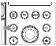
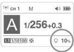
- There are three modes: OFF, Percentage and PROP. Short press the Modeling Lamp Button, and the three mode will be displayed on the LCD panel in sequence.
- OFF: the modeling lamp is off.
- Percentage: 1%\~100%
- PROP: The modeling lamp's power changes with the flash's power. The bigger power the flash has, the brighter the modeling lamp is.
- Long press the modeling lamp for 2 seconds to adjust the percentage of modeling lamp from 1% to 100% .
Other Applications
Sync Triggering
The Sync Cord Jack is a 3.5mm plug. Insert a trigger plug here and the flash will be fired synchronously with the camera shutter.
To control the flash wirelessly, you need to insert the receive end of flash trigger into the Wireless Control Port on the flash and insert the transmit end into the camera hot shoe. Settings made on the hotshoe-mounted transmit and receive ends will be wirelessly communicated to the flash. Then you can press the camera shutter release button to trigger the flash. You can also hold the transmit end at hand to control your off-camera flash.
The Sync Cord Jack is a 3.5mm plug. Insert a trigger plug here and the flash will be fired synchronously with the camera shutter.
- For full instructions on the use of flash trigger, see its user manual.
Protection Function
1. Over-Temperature Protection
- To avoid overheating and deteriorating the flash head, the inner over-temperature protection function may be activated and f will be displayed after firing more than 100 continuous flashes. If gets a slower recycle time in firing, please allow a rest time of about 5 minutes, and the flash unit will then return to normal and the f will disappear.
- The inner over-temperature protection function may be activated when firing more than 200 continuous flashes in fast succession at 1/1 full power and g2q will be displayed. If gets a slower recycle time in firing, please allow a rest time of about 5 minutes, and the flash unit will then return to normal and the g2q will disappear.
2. Other Protections
- The system provides real-time protection to secure the device and your safety. The following lists prompts for your reference:
| Prompts on LCD Panel | Meaning |
| E1 | A failure occurs on the recycling system so that the flash cannot fire.Please restart the flash unit. If the problem still exists, please send this product to a maintenance center. |
| E3 | The voltage on two outlets of the flash tube is too high.Please send this product to a maintenance center. |
| E9 | There are some errors occurred during the upgrading process.Please using the correct firmware upgrade method. |
Technical Data
| Model | AD1200Pro Kit | |
| Flash Mode | Wireless off | M/Multi |
| Slave unit of radio transmission | TTL/M/Multi | |
| Compatible Cameras under Radio Transmission (as slave unit) | compatible with Canon, Nikon, Sony, Olympus, Panasonic, Fujifilm and Pentax | |
| Guide No. (1/1 output) | 124 (ISO 100, in meters, with high-efficiency standard reflector) | |
| Flash Duration | 1/220 to 1/10860 seconds | |
| POWER | 1200Ws | |
| Power Output | 1/256~1/1 | |
| Stroboscopic Flash | Provided (up to 100 times, 100Hz) | |
| Flash Exposure Compensation (FEC) | Yes, adjust this function on the flash trigger. | |
| Sync Mode | High-speed sync (up to 1/8000 seconds), first-curtain sync, and second-curtain sync | |
| Delay Flash | 0.01~30 seconds | |
| Mask | √ | |
| Fan | √ | |
| Beeper | √ | |
| Modeling Lamp(LED) | 40W | |
| Optic Slave Flash | S1/S2 | |
| Flash Duration Indication | √ | |
| Display | Dot-matrix panel | |
| Wireless Flash (2.4G wireless transmission) | ||
| Wireless Flash Function | Slave, Off | |
| Controllable Slave Groups | 5 (A, B, C, D, and E) | |
| Transmission Range (approx.) | 100m | |
| Channels | 32 (1~32) | |
| Wireless ID | To avoid signal interference effectively, triggering can only be achieved when the channels and wireless IDs of the master and slave unit are set to the same. | |
| Power Supply | ||
| Power Supply | Lithium battery pack (36V/5200mAh) | |
| Full Power Flashes | Approx. 500 | |
| Recycle Time | Approx. 0.01-2s | |
| Battery Indicator | √ | |
| Power Indication | Power off automatically after approx. 30~120 minutes of idle operation. | |
| Sync Triggering Mode | 3.5mm sync line | |
| Color Temperature | 5600±200K | |
| Stable Color Temperature Mode | color temperature changes within 5600±75K over the entire power range. | |
| Dimensions | ||
| Dimension | Flash head: 12.5x23x20cm (reflector is included) | |
| Battery pack: 23.5x14.5x26cm | ||
| Kit Net Weight | 8.25Kg | |
Troubleshooting
If there is a problem, refer to this Troubleshooting Guide.
The flash exposure is underexposed or overexposed.
- You used high-speed sync.
→With high-speed sync, the effective flash range will be shorter. Make sure the subject is within the effective flash range displayed. - You used Manual Flash mode.
→Set the flash mode to TTL or modify the flash output.
Firmware Upgrade
This flash supports firmware upgrade through the USB port. Update information will be released on our official website.
- USB connection line is not included in this product. As the USB port is a Type-C USB socket, please use the Type-C USB line.
- As the firmware upgrade needs the support of Godox G3 software, please download and install the "Godox G3 firmware upgrade software" before upgrading. Then, choose the related firmware file.
- As the products needs to do firmware upgrade, please refer to instruction manual of the newest electric version as final.
Maintenance
- Shut down the device immediately should abnormal operation be detected.
- Avoid sudden impacts and the product should be dedusted regularly.
- It is normal for the flash tube to be warm when in use. Avoid continuous flashes if unnecessary,
- Maintenance of the flash must be performed by our authorized maintenance department which can provide original accessories.
- This product, except consumables, is supported with a one-year warranty.
• Unauthorized service will void the warranty. - If the product had failures or was wetted, do not use it until it is repaired by professionals.
- Changes made to the specifications or designs may not be reflected in this manual.
FCC
This device complies with part 15 of the FCC Rules. Operation is subject to the following two conditions: (1) This device may not cause harmful interference, and (2) this device must accept any interference received, including interference that may cause undesired operation.
Any Changes or modifications not expressly approved by the party responsible for compliance could void the user's authority to operate the equipment.
Note: This equipment has been tested and found to comply with the limits for a Class B digital device, pursuant to part 15 of the FCC Rules. These limits are designed to provide reasonable protection against harmful interference in a residential installation. This equipment generates uses and can radiate radio frequency energy and, if not installed and used in accordance with the instructions, may cause harmful interference to radio communications. However, there is no guarantee that interference will not occur in a particular installation. If this equipment does cause harmful interference to radio or television reception, which can be determined by turning the equipment off and on, the user is encouraged to try to correct the interference by one or more of the following measures:
-Reorient or relocate the receiving antenna.
-Increase the separation between the equipment and receiver.
-Connect the equipment into an outlet on a circuit different from that to which the receiver is connected.
-Consult the dealer or an experienced radio/TV technician for help.
Warning
Operating frequency: 2412.99MHz-2464.49MHz (only receive)
Declaration of Conformity
GODOX Photo Equipment Co.,Ltd. hereby declares that this equipment are in compliance with the essential requirements and other relevant provisions of Directive 2014/58/EU. In accordance with Article 10(2) and Article 10(10), this product is allowed to be used in all EU member states. For more information of DoC, Please click this web link https://www.godox.com/eu-declaration-off-conformity/
The device complies with RF specifications when the device used at 0mm from your body.
Warranty
Dear customers, as this warranty card is an important certificate to apply for our maintenance service, please fill in the following form in coordination with the seller and safe-keep it. Thank you!
| Product Information | Model | Product Code Number |
| Customer Information | Name | Contact Number |
| Address | ||
| Seller Information | Name | |
| Contact Number | ||
| Address | ||
| Date of Sale | ||
| Note: | ||
Note: This form shall be sealed by the seller.
Applicable Products
The document applies to the products listed on the Product Maintenance Information (see below for further information). Other products or accessories (e.g. promotional items, giveaways and additional accessories attached, etc.) are not included in this warranty scope.
Warranty Period
The warranty period of products and accessories is implemented according to the relevant Product Maintenance Information. The warranty period is calculated from the day(purchase date) when the product is bought for the first time, And the purchase date is considered as the date registered onthe warranty card when buying the product.
How to Get the Maintenance Service
If maintenance service is needed, you can directly contact the product distributor or authorized service institutions. You can also contact the Godox after-sale service call and we will offer you service. When applying for maintenance service, you should provide valid warranty card. If you cannot provide valid warranty card, we may offer you maintenance service once confirmed that the product or accessory is involved in the maintenance scope, but that shall not be considered as our obligation.
Inapplicable Cases
The guarantee and service offered by this document are not applicable in the following cases: ①. The product or accessory has expired its warranty period; ②. Breakage or damage caused by inappropriate usage, maintenance or preservation, such as improper packing, improper usage, improper plugging in/out external equipment, falling off or squeezing by external force, contacting or exposing to the improper temperature, solvent, acid, base, flooding and damp environments, etc; ③. Breakage or damage caused by non-authorized institution or staff in the process of installation, maintenance, alternation, addition and detachment; ④. The original identifying information of product or accessory is modified, alternated, or removed; ⑤. No valid warranty card; ⑥. Breakage or damage caused by using illegally authorized, nonstandard or non-public released software; ⑦. Breakage or damage caused by force majeure or accident; ⑧. Breakage or damage that could not be attributed to the product itself. Once met these situations above, you should seek solutions from the related responsible parties and Godox assumes no responsibility. The damage caused by parts, accessories and software that beyond the warranty period or scope is not included in our maintenance scope. The normal discoloration, abrasion and consumption are not the breakage within the maintenance scope.
Maintenance and Service Support Information
The warranty period and service types of products are implemented according to the following Product Maintenance Information:
| Product Type | Name | Maintenance Period(month) | Warranty Service Type |
| Parts | Circuit Board | 12 | Customer sends the product to designated site |
| Battery | 3 | Customer sends the product to designated site | |
| Electrical parts e.g.battery charger, power cord, sync cable, etc. | 12 | Customer sends the product to designated site | |
| Other Items | Flash tube, modeling lamp, lamp body, lamp cover, lockingdevice, package, etc. | No | Without warranty |
Godox After-sale Service Call 0755-29609320-8062



- Foreword
- Warning
- Contents
- Conventions used in this Manual
- Name of Parts
- Included Accessories
- Separately Sold Accessories
- Installing Reflector (Other Accessories)
- Attaching Flash Tube
- Adjusting Handle
- Battery
- Features
- Cautions
- Loading and Unloading the Battery Pack
- Battery Level Indication
- Power Management
- Flash Head Connection
- Wireless Flash Mode
- Flash Mode — TTL Autoflash
- TTL Mode
- High-Speed Sync
- Flash Mode — M: Manual Flash
- Optical S1 Secondary Unit Setting
- Optical S2 Secondary Unit Setting
- Stable Color Temperature Function
- Flash Mode — Multi: Stroboscopic Flash
- Calculating the Shutter Speed
- Number of Flashes / Flash Frequency = Shutter Speed
- Wireless Flash Shooting: Radio (2.4G) Transmission
- Wireless Settings
- Setting the Communication Channel
- Setting the Communication Group
- Wireless Flash Shooting
- Wireless Multiple Flash Shooting
- The Reason & Solution of Not Triggering in Godox 2.4G Wireless
- C.Fn: Setting Custom Functions
- Modeling Lamp
- Other Applications
- Sync Triggering
- Protection Function
- Over-Temperature Protection
- Other Protections
- Troubleshooting
- Firmware Upgrade
- Maintenance
- FCC
- Declaration of Conformity
- Warranty
- Applicable Products
- Warranty Period
- How to Get the Maintenance Service
- Inapplicable Cases
- Maintenance and Service Support Information
Marke : GODOX
Modell : AD1200Pro
Kategorie : Beleuchtung