
RM64 - Mixer ROLLS - Kostenlose Bedienungsanleitung
Finden Sie kostenlos die Bedienungsanleitung des Geräts RM64 ROLLS als PDF.


Benutzerfragen zu RM64 ROLLS
0 Frage zu diesem Gerät. Beantworten Sie die, die Sie kennen, oder stellen Sie Ihre eigene.
Eine neue Frage zu diesem Gerät stellen
Laden Sie die Anleitung für Ihr Mixer kostenlos im PDF-Format! Finden Sie Ihr Handbuch RM64 - ROLLS und nehmen Sie Ihr elektronisches Gerät wieder in die Hand. Auf dieser Seite sind alle Dokumente veröffentlicht, die für die Verwendung Ihres Geräts notwendig sind. RM64 von der Marke ROLLS.
BEDIENUNGSANLEITUNG RM64 ROLLS
text_image
ROLLS www.rolls.com MIC ONE MIC TWO 1 2 MICROPHONE INPUTS SOURCE INSETTING THE REAR PANEL DIP SWITCHES
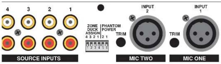
Zone Duck Assign
Switches 1 - 4 engage the Ducking function to the indicated zone.
First - in order for the ducking to operate properly in the assigned zone, the microphones and sources must be assigned to that zone.
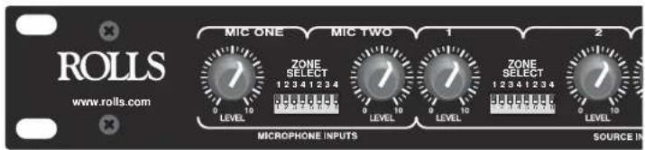
Select which zone you wish to have the ducking function by moving that Zone Duck Assign switch to the DOWN position. BOTH Mic 1 and Mic 2, if assigned to the selected zone and have the Zone Duck Assign switch down, will duck the sources assigned to that zone. For example; shown above - Mic 1 is selected on the front panel to Zones 1 - 4, and Mic 2 is selected only to Zone 1. Shown below, Zone 4 has no ducking assigned, while Zones 1 - 3 have ducking assigned. Therefore, Mic 1 and Mic 2 will duck whatever Source material is present at Zone 1, Mic 1 will additionally duck material at Zones 2 and 3, but not Zone 4. Mic 2, since it is not selected to Zones 2 - 4, it will have no effect on those zones.
text_image
4 3 2 1 SOURCE INPUTS ZONE DUCK ASSIGN 4 3 2 1 PHANTOM POWER 2 1 INPUT 2 TRIM INPUT 1 MIC TWO MIC ONEPhantom Power
Switch 5 applies Phantom Power to Mic 2, Switch 6 applies Phantom Power to Mic 1. The Phantom Power is on when the switch is DOWN.
ROLLS
ROLLS CORPORATION
SALT LAKE CITY, UTAH
06-10
ROLLS
RM64
FOUR ZONE MIXER
Setup Guide
FEATURES:
• Two Microphone and Four RCA Source Inputs
• Four XLR Balanced Zone Outputs
• 12 VDC Phantom Power available for each Mic Input
- Remote Volume control jacks for each Zone Output
• Switchable Ducking for the Mic Inputs
SPECIFICATIONS
| Input | Impedance: | 10K | Ohms unbalanced | balance RC | ||
| 50K | Ohms | |||||
| Output Impedance: 50 Ohms Balanced XLR | ||||||
| Max Input Level: Mic: +10 dB | ||||||
| Source: | +22 | dB | ||||
| Phantom Power: +12 Volts DC, 5mA max. | ||||||
| Input | Connectors: | XLR | and | RCA | ||
| Outputs: | 4 | ea. | XLR | |||
| Max | Gain: | 60 | dB | mic | ||
| 30 dB line | ||||||
| S/N | Ratio: | >75 | dB | |||
| THD | < | .3% | ||||
| IMD | (SMPTE) | < | .3% | |||
| CMRR | 90 | dB | ||||
| Frequency Response: | 20Hz to 20kHz +/- 0 dB | |||||
| Power | 120 | VAC | 50-60 | Hz, | ||
| Weight: | 7 | Ibs | (3KG) | |||
| Size: | 19" | x | 1.75" | x | 6.5" | |
| (48cm) | x | 4.5cm | x | |||
Thank your for your purchase of the Rolls RM64 Four Zone Mixer. The RM64 combines two paging microphones with up to four line level source inputs. Each input is switch selected to output to any combination of four zone outputs. The outputs are all balanced XLR connectors, and a 1/4" Remote Volume jack provides each zone with the means for external volume control. The Microphone inputs feature automatic ducking for easy paging.
The RM64 is the ideal solution for banquet rooms, offices, restaurant/night clubs, etc. NOTE: This unit is intended for professional installation. Certain assumptions have been made that the installer has the required knowledge to properly install, setup and operate the RM64.
INSPECTION/WARRANTY
- Unpack and inspect the RM64 box and package.
If obvious physical damage is noticed, contact the carrier immediately to make a damage claim. We suggest saving the shipping carton and packing materials for safely transporting the unit in the future.
- Please visit our website at www.rolls.com for Warranty Information and Registration.
FRONT PANEL

text_image
ROLLS 20Hz 1 20Hz 1 20Hz 1 20Hz 1 20Hz 1 20Hz 1 20Hz 1 20Hz 1 20Hz 1 20Hz 1 20Hz 1 20Hz 1 20Hz 1 20Hz 1 20Hz 1 20Hz 1 20Hz 1 20kHz 1 20kHz 1 20kHz 1 20kHz 1 20kHz 1 20kHz 1 20kHz 1 20kHz 1 20kHz 1 20kHz 1 20kHz 1 20kHz 1 20kHz 1 20kHz 1 20kHz 1 20kHz 1 20kHz 1 394MIC INPUTS 1, 2: These LEVEL controls adjust the volume of the indicated Microphone channel.
SOURCE INPUTS 1 - 4: These LEVEL controls adjust the volume of the indicated Source channel.
ZONE SELECT: DIP switches for assigning the indicated Mic or Source channel to the Zone Outputs. The four switches closest to the channel LEVEL control assign that channel to the zones.
ZONE OUTPUTS: These LEVEL controls adjust the output volume of the indicated ZONE.
CH 4 INPUT: 3.5mm (1/8" stereo) line level input for channel 4.
pwr LED: When lit, indicates the RM64 is on.
Power switch: Turns the RM64 on and off.
REAR PANEL

text_image
ROLLS 10V 2.5V 3.5V 20V 4.5V 5.5V 30V 6.5V 7.5V 40V 8.5V 9.5V 50V 10.5V 11.5V 60V 12.5V 13.5V 70V 14.5V 15.5V 80V 16.5V 17.5V 90V 18.5V 19.5V CEZONE OUTPUTS 1 - 4: Line level (+4 dB ref.) balanced male XLR jacks for connection to the zone amplifiers.
REMOTE VOLUME: These four 1/4" TRS jacks connect to a remote volume potentiometer.
SOURCE INPUTS 1 - 4: RCA input jacks for connection to CD Players, Tuners etc.
ZONE DUCK ASSIGN/PHANTOM POWER SWITCHES: This set of DIP switches, from left to right; the first four assign which zone will have the source signal(s) ducked by the Microphone Inputs, the last two apply phantom power to the indicated microphone channel.
MIC INPUT 1 - 2: Balanced female XLR jacks for connection to dynamic or condenser type microphones.
TRIM 1 - 2: Adjusts the input sensitivity for the indicated Mic Input.
CONNECTION INFORMATION
text_image
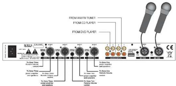
FROM AM/FM TUNER FROM CD PLAYER FROM DVD PLAYER To Zone Three Power amplifier and speakers To Zone Three Remote Volume control To Zone Three Power amplifier and speakers To Zone Three Power amplifier and speakers To Zone Three Remote Volume control To Zone Core Power amplifier and speakers To Zone Core Remote Volume control To Zone Core Power amplifier and speakers To Zone Core Remote Volume controlReferring to the diagram above, connect microphones to the MIC INPUTs and apply phantom power where needed by moving the corresponding Phantom Power switch to the DOWN position. Connect sources such as cassette players, CD players, AM/FM tuners, etc. to the RCA Source Inputs. Note which input each device is connected to as that input corresponds to its front panel Level control. Connect the XLR outputs to their respective zone amplifiers and speakers. The balanced signals are confi gured pin 2 hot, pin 3 neutral, and pin 1 ground. For ground lifting, it will be necessary to remove the connection to pin 1.
REMOTE VOLUME INFORMATION
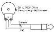
For Remote Volume operation, a Tip-Ring-Sleeve plug will need to be wired to a 10 - 100 K Ohm potentiometer (NEITHER INCLUDED) as shown here.
text_image
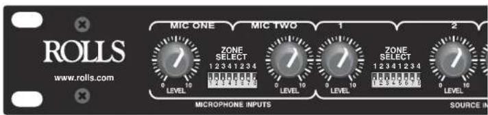
ROLLS www.rolls.com MIC ONE MIC TWO 1 2 ZONE SELECT 1 2 3 4 1 2 3 4 0 1 0 0 0 0 0 0 0 LEVEL LEVEL LEVEL LEVEL MICROPHONE INPUTS SOURCE INSETTING THE FRONT PANEL DIP SWITCHES
Each input is assigned to a Zone via the four DIP switches nearest that Input Level control. The zone is assigned when the switch is in the DOWN position. For example, the switch settings above send Mic 1 to all four Zones; 1, 2, 3, and 4. Mic 2 is sent to Zone 1 only. Source 1 is sent to Zone 1, and Source 2 is sent to Zones 2, 3, and 4.