
RFPEQU - Hi-Fi Rockford Fosgate - Kostenlose Bedienungsanleitung
Finden Sie kostenlos die Bedienungsanleitung des Geräts RFPEQU Rockford Fosgate als PDF.


| Produkttyp | Graphischer Equalizer / Signalprozessor |
| Marke | Rockford Fosgate |
| Modell | RFPEQU |
| Abmessungen (B x H x T) | 482 x 88 x 200 mm (2 HE) |
| Gewicht | ca. 2,5 kg |
| Stromversorgung | 12 V DC (Fahrzeugbordnetz) |
| Anzahl der Bänder | 31 Bänder (1/3 Oktave) |
| Eingänge | 2x Cinch (L/R), 1x AUX 3,5 mm |
| Ausgänge | 4x Cinch (Front, Rear, Subwoofer) |
| Frequenzgang | 20 Hz - 20 kHz (±0,5 dB) |
| Signal-Rausch-Abstand | > 100 dB |
| Klirrfaktor (THD) | < 0,01 % |
| Betriebstemperatur | -20 °C bis +60 °C |
| Gehäusematerial | Aluminiumfrontplatte, Stahlchassis |
| Farbe | Schwarz |
| Montage | 19-Zoll-Rackeinbau (2 HE) |
| Mitgeliefertes Zubehör | Netzkabel, Cinch-Kabel, Bedienungsanleitung |
| Herstellergarantie | 2 Jahre |
| Ursprungsland | China |
Häufig gestellte Fragen - RFPEQU Rockford Fosgate
Benutzerfragen zu RFPEQU Rockford Fosgate
0 Frage zu diesem Gerät. Beantworten Sie die, die Sie kennen, oder stellen Sie Ihre eigene.
Eine neue Frage zu diesem Gerät stellen
Laden Sie die Anleitung für Ihr Hi-Fi kostenlos im PDF-Format! Finden Sie Ihr Handbuch RFPEQU - Rockford Fosgate und nehmen Sie Ihr elektronisches Gerät wieder in die Hand. Auf dieser Seite sind alle Dokumente veröffentlicht, die für die Verwendung Ihres Geräts notwendig sind. RFPEQU von der Marke Rockford Fosgate.
BEDIENUNGSANLEITUNG RFPEQU Rockford Fosgate
Universal PEQ Quick Setup
Features
• Built-in Line Driver
• Accepts High/Low Level Inputs
- Auto Turn-on
• Universal Punch EQ
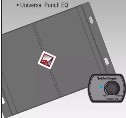
Specifications
Operating Voltage 9-16V
Idle Current 200mA
Frequency Response 20Hz-20kHz
Output Voltage 10V
THD+N 0.005%
Turn-on Delay <1.0 sec
Output Impedance 500 Ohms
Input Sensitivity 600mV-10V
S/N Ratio - CEA 2006 >100dB
S/N Ratio - 10V >110dB
Channel Separation >80dB
Common Mode Rejection Ratio >50dB
Fuse Rating 1A
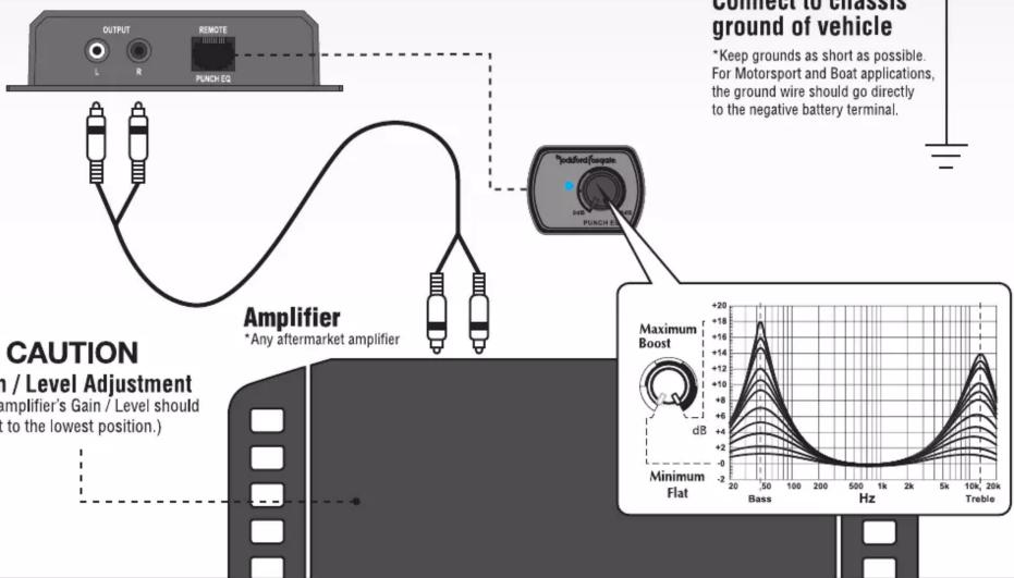
Punch EQ 0-18dB @ 45Hz LP
0-14dB @ 12.5kHz HP

Source Unit
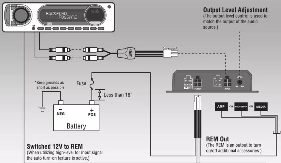

Rockford Fosgate

CAUTION
Gain / Level Adjustment
(The amplifier's Gain / Level should be set to the lowest position.)
PEQ Remote Installation
The remote can be mounted in a variety of ways. Use the following instructions to mount the remote that suits your application.
- Find a location that gives easy access to the remote.
- Route the cable for the remote and connect to the amplifier, Figure 1.
Outside Panel Install
- Using the screws supplied, install the mounting clip.
NOTE: The housing can be installed with the mounting tab up or down.
See Step 1 in Figure 2, use a small flat-blade screwdriver in the slot at the top of the remote and pry the remote assembly from the housing. Reinstall housing as desired.
- Slip the remote onto the mounting clip until it snaps into place.
- Connect the cable to the back of the remote.
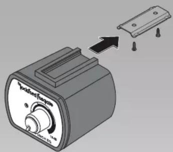
Figure 1
Panel Install-Disassembly
NOTE: The maximum panel thickness is 3/16" (0.1875" or 4.75mm) for this type of installation. Disassemble the remote as shown in Figure 2 as follows;
- Use a small flat-blade screwdriver in the slot at the top of the remote and pry the remote assembly from the housing.
- Pull the control knob straight off to remove.
- Use a paper clip or the flat side of a small drill bit from the back side through the hole to push the cover plate off the housing cover.
NOTE: If the clear plastic LED extender is attached to the cover plate, remove it.
- Remove the nut and washer and remove the remote assembly from the housing cover.
Panel Install-Standard
Ensure there is enough room within the panel area for connection and placement.
- Use the plate with the LED hole as a template for hole positions.
- Drill a 9/32" hole (0.281" or 7.14mm) for the knob shaft and a 3/32" hole (0.094" or 2.39mm) for the LED through hole.
- Install the remote from the back side of the panel, aligning the knob shaft and LED with the drilled holes.
- Install the cover plate washer and nut. Do not over-tighten the nut, just tighten until firm and secure.
- Turn the knob shaft counter-clockwise to it's lowest setting. Position and install the knob.
- Connect the cable to the back of the remote.
Panel Install-Separated LED Placement
CAUTION: We suggest the following be done only by an experienced installer. Use of a grommet and/or double-sided tape (both not included) may be needed for a proper fit of the LED. Rockford Fosgate will in no way be held responsible for damage incurred by improper or novice installation.
Ensure there is enough room within the panel area for connection and placement.
- Remove the LED from the remote assembly by pulling straight up, Figure 3
- Connect the supplied cord to the LED.
- Connect the cord from the LED into the 2-pin connector behind the knob shaft housing.
- Drill a 9/32" hole (0.281" or 7.14mm) for the knob shaft.
- Install the remote from the back side of the panel, aligning the knob shaft with the drilled hole.
- Install the cover plate without LED hole, washer and nut. Do not over-tighten the nut, just tighten until firm and secure.
- Turn the knob shaft counter-clockwise to it's lowest setting. Position and install the knob.
- Locate the position of the LED hole where the cord is not being over-extended.
- Depending on the method of mounting, either a grommet and/or double-sided tape, drill the hole for a snug fit. Install the LED.
- Connect the cable to the back of the remote.
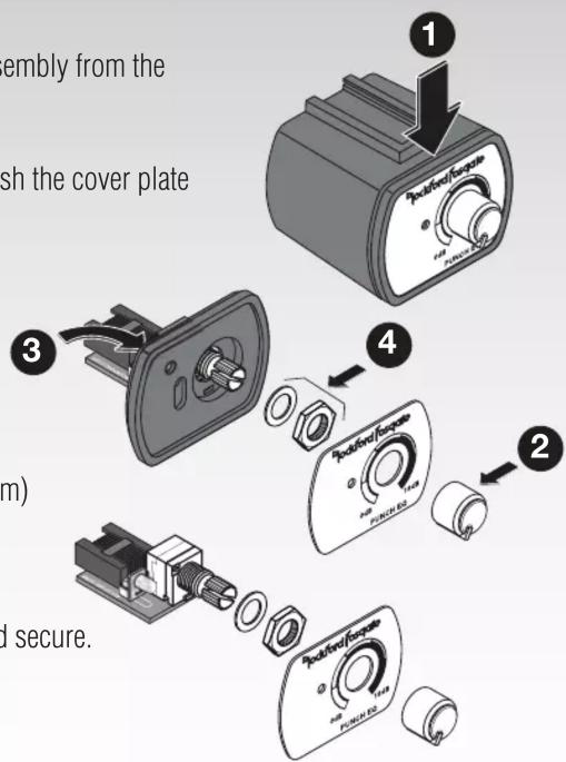
Figure 2
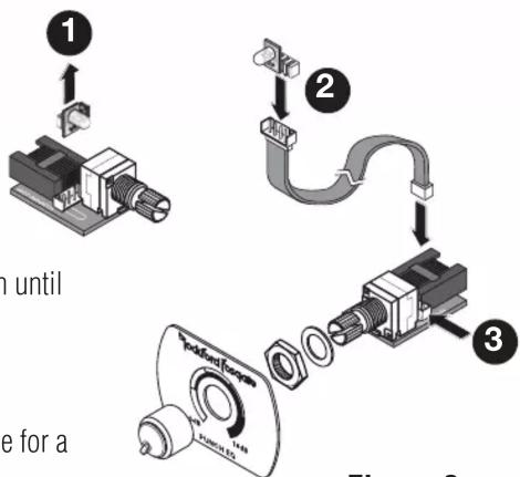
Figure 3
CAUTION: Over excursion and subsequent damage may occur at high levels of boost.

Marke : Rockford Fosgate
Modell : RFPEQU
Kategorie : Hi-Fi