
TL-SL1218MP - Schalter TP-LINK - Kostenlose Bedienungsanleitung
Finden Sie kostenlos die Bedienungsanleitung des Geräts TL-SL1218MP TP-LINK als PDF.


| Produkttyp | Gemanagter Switch (Smart) |
| Anzahl der Ports | 18 (16 x 10/100 Mbit/s PoE+ 2 x SFP) |
| PoE-Leistung | Gesamtbudget: 150 W, max. 30 W pro Port |
| Abmessungen (B x T x H) | 294 x 180 x 44 mm |
| Gewicht | 1,5 kg |
| Stromversorgung | Externes Netzteil, 53,5 V / 3,5 A |
| Energieverbrauch | Max. 185 W (mit PoE-Ausgang) |
| Betriebsumgebung | Temperatur: 0–50 °C, Luftfeuchtigkeit: 10–90 % (nicht kondensierend) |
| Montage | Wandmontage möglich, Tischaufstellung |
| Lüfter | 1 x Lüfter (temperaturgesteuert) |
| Management | Webinterface, SNMP, CLI (über serielle Konsole) |
| VLAN | 802.1Q VLAN, bis zu 256 Gruppen |
| Quality of Service (QoS) | 802.1p, Port-basiert, DSCP |
| Sicherheit | 802.1X, ACL, Port-Sicherheit |
| Lieferumfang | Switch, Netzteil, Montagematerial, Kurzanleitung |
| Garantie | 5 Jahre |
Häufig gestellte Fragen - TL-SL1218MP TP-LINK
Benutzerfragen zu TL-SL1218MP TP-LINK
0 Frage zu diesem Gerät. Beantworten Sie die, die Sie kennen, oder stellen Sie Ihre eigene.
Eine neue Frage zu diesem Gerät stellen
Laden Sie die Anleitung für Ihr Schalter kostenlos im PDF-Format! Finden Sie Ihr Handbuch TL-SL1218MP - TP-LINK und nehmen Sie Ihr elektronisches Gerät wieder in die Hand. Auf dieser Seite sind alle Dokumente veröffentlicht, die für die Verwendung Ihres Geräts notwendig sind. TL-SL1218MP von der Marke TP-LINK.
BEDIENUNGSANLEITUNG TL-SL1218MP TP-LINK
Wall Mounting Guide
Wall Mountable Switches
1.1 Wall Mounting Preparation
Before mounting the switch, you need to prepare the tools below:
- A screw driver.
- Two screws which complies to the corresponding standard. For details, see Wall Mounting Specification.
1.2 Wall Mounting Procedure
On the bottom of the panel, there are two mounting holes. You need to drive two screws into the wall, then mount the switch on the wall. Note that the switch should be mounted on the wall upright rather than sideways.
1) Determine the location on the wall where you want to mount the switch.
2) Mark the wall where the two mounting holes are. The distance between the two marks must be the same as that between the two mounting holes of the switch. For the wall-mounting-holes distance, see Wall Mounting Specification.
3) Drive the screws into the wall at the marks using the screw driver. For the Screw-Head-to-Wall Minimum Distance, see Wall Mounting Specification.
4) Mount the switch on the wall.
1.3 Wall Mounting Specification
| Model | Screw Standard of ANSI B1.1 | Minimum Length of Screw | Screw-Head-to-Wall Minimum Distance | Wall-Mounting-Holes Distance |
| LS105G 4#, (5#), 6# 7mm | 1.5mm 76mm | |||
| LS108G 4#, (5#), 6# 7mm | 1.5mm 65mm | |||
| LS1005G 4#, (5#), 6# 7mm | 1.5mm 38mm | |||
| LS1008G 4#, (5#), 6# 7mm | 1.5mm 48mm | |||
| TL-SF1005LP 4#, (5#), 6#, | 8# 8.5mm 1.5mm 39mm | |||
| TL-SF1005P 4#, (5#), 6#, | 8# 8.5mm 1.5mm 39mm | |||
| TL-SF1006P 4#, (5#), 6#, | 8# 8.5mm 1.5mm 94mm | |||
| TL-SF1008LP 4#, (5#), 6#, | 8# 8.5mm 1.5mm 105mm | |||
| TL-SF1008P 4#, (5#), 6#, | 8# 8.5mm 1.5mm 105mm | |||
| TL-SF1009P 4#, (5#), 6#, | 8# 8.5mm 1.5mm 105mm | |||
| TL-SG1005LP 4#, (5#), 6#, | 8# 8.5mm 1.5mm 39mm | |||
| TL-SG1005P | 4#, (5#), 6#, 8# 8.5mm 1.5mm 39mm | |||
| TL-SG1008D | 4# | 8mm 2mm | 100mm | |
| TL-SG1008P | 4#, (5#), 6#, 8# 8.5mm 1.5mm 105mm | |||
| TL-SG105 | 4#, (5#), 6# 7mm | 1.5mm 39mm | ||
| TL-SG105E 4#, (5#), 6# 7mm | 1.5mm 52mm | |||
| TL-SG105-M2 | 4#, (5#), 6# 7mm | 1.5mm 150mm | ||
| TL-SG105PE | 4#, (5#), 6# 7mm | 1.5mm 39mm | ||
| TL-SG105S 4#, (5#), 6# 7mm | 1.5mm 39mm | |||
| TL-SG108 4#, (5#), 6#, 8# | 8.5mm 1.5mm 94mm | |||
| TL-SG108E | 4#, (5#), 6# 7mm | 1.5mm 110mm | ||
| TL-SG108-M2 | 4#, (5#), 6# 7mm | 1.5mm 150mm | ||
| TL-SG108PE 4#, (5#), 6#, 8# | 8.5mm 1.5mm 94mm | |||
| TL-SG108S 4#, (5#), 6# 7mm | 1.5mm 94mm | |||
| TL-SG116 4#, 6# 8.5mm | 1.5mm 200mm | |||
| TL-SG116E 4#, 6# 8.5mm | 1.5mm 200mm | |||
| TL-SG1210MP 4#, (5#), 6#, 8# | 8.5mm 1.5mm 150mm | |||
| TL-SG1210MPE 4#, (5#), 6#, 8# | 8.5mm 1.5mm 150mm | |||
| TL-SG1210P 4#, (5#), 6#, 8# | 7mm 1.5mm 150mm | |||
| TL-SG2008 4#, (5#), 6# 7mm | 1.5mm 150mm | |||
| TL-SL1210MP | 4#, (5#), 6#, 8# | 7mm 1.5mm 150mm | ||
| TL-SL1311MP | 4#, (5#), 6#, 8# | 8.5mm 1.5mm 150mm | ||
| TL-SX105 | 4#, (5#), 6# 7mm | 1.5mm 150mm |
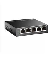


Marke : TP-LINK
Modell : TL-SL1218MP
Kategorie : Schalter