MXJ-YA3419M - Klimaanlage SAMSUNG - Kostenlose Bedienungsanleitung
Finden Sie kostenlos die Bedienungsanleitung des Geräts MXJ-YA3419M SAMSUNG als PDF.


Benutzerfragen zu MXJ-YA3419M SAMSUNG
0 Frage zu diesem Gerät. Beantworten Sie die, die Sie kennen, oder stellen Sie Ihre eigene.
Eine neue Frage zu diesem Gerät stellen
Laden Sie die Anleitung für Ihr Klimaanlage kostenlos im PDF-Format! Finden Sie Ihr Handbuch MXJ-YA3419M - SAMSUNG und nehmen Sie Ihr elektronisches Gerät wieder in die Hand. Auf dieser Seite sind alle Dokumente veröffentlicht, die für die Verwendung Ihres Geräts notwendig sind. MXJ-YA3419M von der Marke SAMSUNG.
BEDIENUNGSANLEITUNG MXJ-YA3419M SAMSUNG
INSTALLATION MANUAL
Please read 'Safety Precautions' described in the installation manual of the air conditioner.
- Check the following parts in the package.
- For further information of the piping material and size of the refrigerant pipes, refer to the installation manual of the air conditioner.
Requirement
- Condensate may occur on the heat insulation surface according to the atmosphere inside of the ceiling.
- If the inside of the ceiling has high temperature or humidity rate is more than 80%, please add proper insulation to prevent water drops.
• The stopper area of the pipe or socket should be spread with a welding material. EX)

Branch joints
Y-joint
| Name\Model | MXJ-YA1509M MXJ-YA2512M MXJ-YA2812M MXJ-YA2815M MXJ-YA3419M MXJ-YA4119M MXJ-YA4422M | ||||||
| Liquid side | |||||||
| Gas side | |||||||
Reducer
| Model name Total indoor unit's capacities | |
| MXJ-YA1509M | 15.0 kW (51 MBH) and below |
| MXJ-YA2512M | Over 15.0~40.0 kW (51~136 MBH) and below |
| MXJ-YA2812M | Over 40.0~45.0 kW (136~154 MBH) and below |
| MXJ-YA2815M | Over 45.0~70.3 kW (154~240 MBH) and below |
| MXJ-YA3419M | Over 70.3~98.4 kW (240~336 MBH) and below |
| MXJ-YA4119M | Over 98.4~135.2 kW (336~461 MBH) and below |
| MXJ-YA4422M | Over 135.2 kW (461 MBH) |
Y-joint for HR (High pressure gas)
| Model | Reducer | |||
| MXJ-YA1500M | MXJ-YA2500M | MXJ-YA3100M | MXJ-YA3800M | |
Header joint
| Name\Model | MXJ-HA2512M MXJ-HA3115M | MXJ-HA3819M | ||
| Liquid side | 1x4CA 2x-CA 7D x1CA | 1x8CA 4x1CA 7D x1CA | 1x8CA 7D x1CA | |
| Gas side | 3x4±A 5x'±A 8x1±A | 3x8±A 6x1BA 8x2BA | 3x8BA 8x2BA | |
Outdoor joint
| Name\Model | MXJ-TA3819M | MXJ-TA3419M | MXJ-TA4422M | MXJ-TA4122M |
| Liquid side | ||||
| Gas side |
Outdoor joint for HR (High pressure gas)
| Model | Reducer | ||||
| MXJ-TA3100M | MXJ-TA3800M | ||||
Connecting Method
Installing the Y-joint
Install the Y-joint 'horizontally' or 'vertically'.
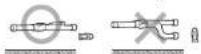

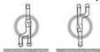

Keep a minimum distance of 500mm or more before connecting a branch joint.
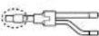
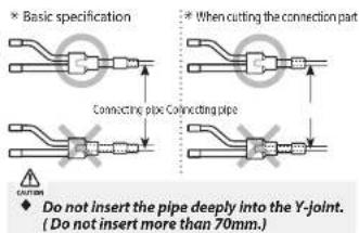
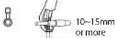
- Use connection part of Y-joint or provided reducer by cutting them in accordance with diameter of connecting pipe.
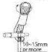
Make certain 10\~15mm or more for reducer which connected with pipe.
- Remove burr on cut part of reducer. It is impossible to connect reducer with pipe, if pipe is deformed or reducer is untrimmed.
text_image
Basic specification When cutting the connection part Connecting pipe Connecting pipe Do not insert the pipe deeply into the Y-joint. (Do not insert more than 70mm.)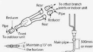
text_image
Rear To other branch joints or indoor unit Pipe Reducer Front To outdoor unit Pipe Rear Main pipe 500mm or more Maintain ±15° on the horizon* Install the Y-joint within ±15° on the horizon or on the vertical.
Installing the Header joint
- Select the reducer fitted on the diameter of the pipe.
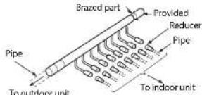
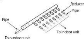
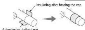
- Block the reducer that is not used by brazing the cap if the number of connected indoor unit is fewer than header joint holes.
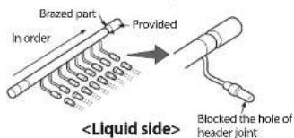
text_image
Brazed part In order Provided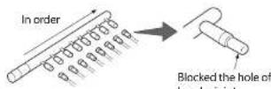
Note Connect the header joint to the pipe by cutting the provided reducer properly.
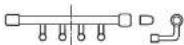

△
Connect the header joint in order respecting the number of the indoor unit.
◆ Connet the indoor unit as the highest capacity comes first.
- Install the header joint horizontally.
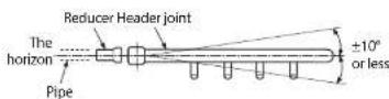


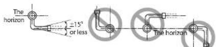
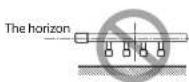
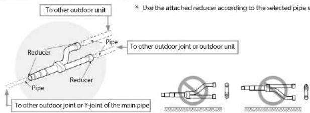
Installing the Outdoor joint
text_image
To other outdoor unit Reducer Pipe Pipe To other outdoor joint or outdoor unit Reducer Pipe To other outdoor joint or Y-joint of the main pipe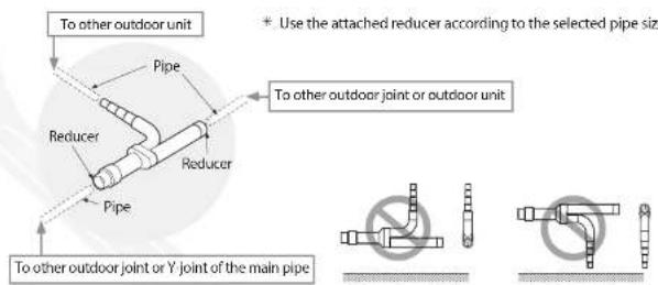
text_image
To other outdoor unit Pipe Reducer Pipe To other outdoor joint or outdoor unit + Use the attached reducer according to the selected pipe size To other outdoor joint or Y joint of the main pipe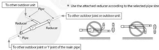
text_image
To other outdoor unit Pipe Reducer Pipe Reducer Pipe To other outdoor joint or outdoor unit * Use the attached reducer according to the selected pipe size. To other outdoor joint or Y-joint of the main pipeNote Connect the Outdoor joint to the pipe by cutting the outlet of the Outdoor joint or provided reducer properly.

text_image
10~15mm or moreInstallation of outdoor joints
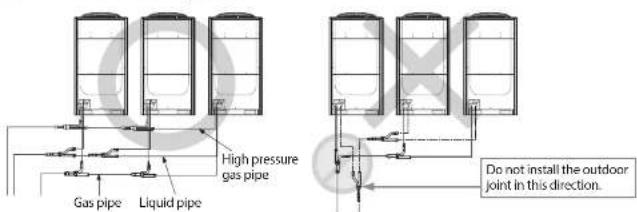
text_image
High pressure gas pipe Gas pipe Liquid pipe Do not install the outdoor joint in this direction.* High pressure gas pipe only applies to the HR product.
Insulating the branch joint
Y-joint & liquid side & gas side of the outdoor unit
◆ Attach the insulation provided with a branch joint to the insulation supplied in the field without a gap. Wrap the connected part with an insulation (Field supply) of a thickness of at least 10mm.
◆ Use an insulation with the heat resisting temperature over 120°C. Wrap the branch joint with an insulation of a thickness of at least 10mm.
When insulating in high humidity(higher than 30°C, 80%), wrap the supplied insulation with more than 10mm of extra insulation such as Polyethylene Foam or other similar material.
◆ Wrap the connected part between the Outdoor joint and the gas side of the outdoor unit to prevent it from defrosting. Wrap gas side pipe of the outdoor unit wholly to prevent it from dewing.
Pipe insulation
(Field supply) Provided Fix securely without any gap.
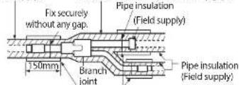
text_image
Fix securely without any gap. 50mm Branch joint Pipe insulation (Field supply) Pipe insulation (Field supply)A thickness of the insulation (Field supply) should be at least 10mm.
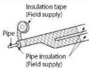
* Attach the adhesive insulation tape to the pipe as shown in the picture after insulating the pipe.
Header joint
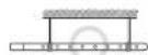
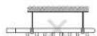
◆ Cover the connected part and fasten the header joint using a cable tie.
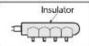
◆ Insulate the header joint and the brazed part and wrap the connected part with an adhesive insulation tape to prevent it from dewing.