
J220 - Laufband TUNTURI - Kostenlose Bedienungsanleitung
Finden Sie kostenlos die Bedienungsanleitung des Geräts J220 TUNTURI als PDF.


| Produkttyp | Laufband |
| Marke | Tunturi |
| Modell | J220 |
| Abmessungen (L x B x H) | 147 x 74 x 140 cm |
| Gewicht | 38 kg |
| Lauffläche | 38 x 123 cm |
| Neigungsstufen | 3 (10%, 13%, 16%) |
| Widerstandsstufen | 8 |
| Max. Benutzergewicht | 100 kg (225 lbs) |
| Stromversorgung Display | 1 x 1,5 V AA-Batterie |
| Funktionen | Geschwindigkeit, Zeit, Distanz, Kalorien, Scan |
| Sicherheitshinweise | Nur eine Person gleichzeitig, ärztliche Rücksprache empfohlen, Bei Schwindel sofort anhalten |
| Wartungsintervall | Schmierung ca. alle 6 Monate (je nach Nutzung) |
| Schmieröl | Nur Tunturi-Schmieröl verwenden |
| Transport | Transportrollen an der Vorderseite |
| Garantie | Volle Tunturi-Garantie für den Hausgebrauch |
Häufig gestellte Fragen - J220 TUNTURI
Benutzerfragen zu J220 TUNTURI
0 Frage zu diesem Gerät. Beantworten Sie die, die Sie kennen, oder stellen Sie Ihre eigene.
Eine neue Frage zu diesem Gerät stellen
Laden Sie die Anleitung für Ihr Laufband kostenlos im PDF-Format! Finden Sie Ihr Handbuch J220 - TUNTURI und nehmen Sie Ihr elektronisches Gerät wieder in die Hand. Auf dieser Seite sind alle Dokumente veröffentlicht, die für die Verwendung Ihres Geräts notwendig sind. J220 von der Marke TUNTURI.
BEDIENUNGSANLEITUNG J220 TUNTURI
ECB TREADMILL J 220
GB OWNER'S MANUAL
D BETRIEBSANLEITUNG
F MODE D'EMPLOI
I MANUALE D'USO
E MANUAL DEL USUARIO
S BRUKSANVISNING
FIN KÄYTTÖOHJE

natural_image
Illustration of a Tunturi bicycle with attached ECB treadmill (no text or symbols on the diagram itself)583 4012 A
REMARKS AND WARNINGS
THE EQUIPMENT HAS BEEN DESIGNED FOR DOMESTIC USE, FOR WHICH THE FULL TUNTURI WARRANTY APPLIES.
Please read this owner's manual through carefully before assembling, using and servicing the treadmill! Follow the instructions given in this manual carefully.
* Before you start any training, consult a physician to check your state of health.
* If you experience nausea, dizziness or other abnormal symptoms while exercising, stop your workout at once and consult a physician.
* Parents or others responsible for children should note that children's natural playfulness and curiosity may lead to situations and behaviour for which the treadmill is not designed. If children are allowed to use the treadmill, they should be supervised and taught to use the treadmill properly, keeping in mind the child's physical and mental development and their personality. The treadmill is not a toy.
* Only one person may use the treadmill at a time.
* Place the treadmill on a firm, level surface.
* Before you start using the treadmill, make sure that it functions correctly in every way. Do not use a faulty device.
* Hold the handlebar for support when getting on or off the treadmill.
* Wear appropriate clothing and shoes when exercising. Make sure that your shoe laces are properly tied. If possible use sports shoes intended for indoor use only. Small stones, sand or gravel in the soles of outdoor shoes may cause unnecessary wear or other damage to the treadmill.
* Always keep your hands well away from moving parts.
* To avoid muscular pain, begin and end each workout by stretching, warming up and cooling down (slow jogging or walking).
* Do not attempt any servicing or adjustment other than those described in this manual. The service instructions must be followed carefully.
* The magnet caliper of the magnetic brake forms an extremely powerful magnetic field which may damage the mechanism of a watch or the magnetic identification tape of a credit or cash card if they come into immediate contact with the magnets. Never attempt to detach or remove the magnet caliper of the magnetic brake.
* The maximum user weight or 100 kg 225 lbs.
THE FIGURES REFERRED TO IN THE TEXT ARE IN THE BACK FOLD.
1. ASSEMBLY
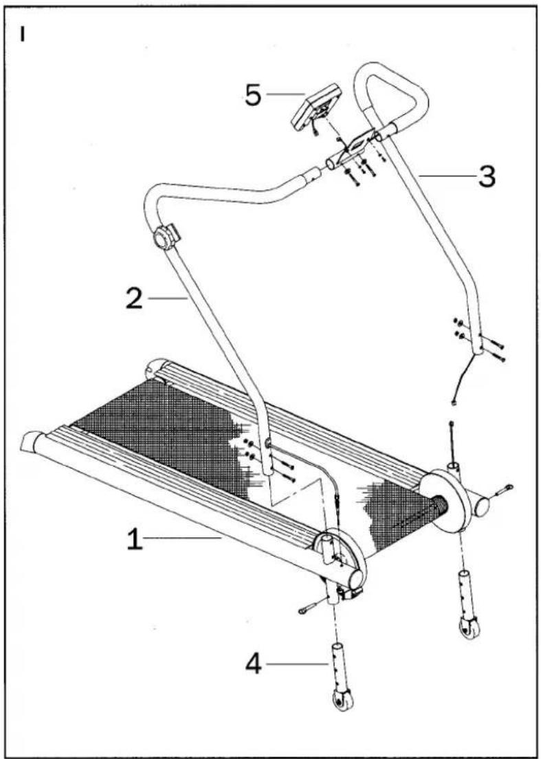
Before starting the assembly, please make sure that the following items are included in the package (fig. 1):
| 1) | Main body | 1 pc |
| 2) | Right handlebar | 1 pc |
| 3) | Left handlebar | 1 pc |
| 4) | Support foot with transportation wheel | 2 pcs |
| 5) | Meter | 1 pc |
| Fastener and tool set | ||
| - hex screw | 4 pcs | |
| - nut | 2 pcs | |
| - crosshead screw | 2 pcs | |
| - hex wrench | 1 pc |
If you notice that a part is missing, contact the dealer and give the model (J 220), serial number and spare part number, which you can find in the spare parts list at the back of this manual.
Once the treadmill and all its parts have been unpacked, assemble as follows (left, right, front and back are as seen from the exercising position):
1.1. MOUNTING THE SUPPORT FEET
Fit the right support foot into the tube in the right-hand side front part of the main body and adjust to the desired height (fig. 2).
Secure with the locking pin, making sure that the holes are in alignment.
Repeat for the left support foot.
1.2. MOUNTING THE HANDLEBARS
Fit the right handlebar tube onto the tube on the right side of the main body (fig. 3).
Connect the meter cable coming out of the left handlebar to the meter cable coming out of the left main body tube.
Fit the left handlebar onto the tube on the left main body tube.

NOTE!
Make sure the meter cable is not pinched as this may cause damage to the cable.
Thread the cable coming from the top of the left handlebar through the hole in the middle of the console bracket. Join the left and right handlebars together by pushing the tops of the handlebar tubes into the console bracket (fig. 3). Secure with two hex screws.
Secure the lower ends of handlebars with two hex screws and a nut.
1.3. MOUNTING THE RESISTANCE ADJUSTMENT MECHANISM
Make sure that the resistance is set at the minimum ("0").
Thread the resistance adjustment cable through the hole in the right main body tube (fig. 4).
Loosen the adjustment nut (A) until you can place the spring (B) on the end of the cable under the main body tube and place the end of the wire coming from the cable in the notch on the magnetic caliper.
Set the resistance at the maximum ("8").
Tighten the cable adjustment nut (A) until the screw (C) touches the main body tube.
The distance between the magnetic caliper and the flywheel should now be approximately 2 mm or 1/16" (never less than 1 mm).
Tighten the lock nut (D).
1.4. MOUNTING THE METER
Put one 1.5 V AA battery into the battery holder at the back of the meter.
Plug the meter cable into the socket on the rear of the meter.
Thread the cables into the groove at the back of the meter to avoid damage during mounting.
Fit the meter into place and secure with two crosshead screws (fig. 5).
Make sure that the belt is running true and that the belt tension is correct (see ADJUSTING THE BELT ALIGNMENT and ADJUSTING THE BELT TENSION).
The treadmill is now ready for use.
2. USE
The Tunturi ECB Treadmill J 220 is a versatile basic treadmill for walking, jogging and running in your home.
Walking and jogging are excellent forms of aerobic exercise. The basic idea is that sufficiently gentle exercise can be carried on for a fairly long time. Aerobic exercise improves the maximal oxygen uptake capacity, which translates into improved endurance and fitness. The capacity of the human body to burn fat depends directly on its capacity to carry oxygen.
Aerobic exercise is meant to be enjoyable. You should work up a light sweat but you should not get out of breath during exercise. For instance, you should be able to talk while jogging. You should exercise for 30 minutes at least three times a week. This is how you build up basic fitness. When you have reached this stage, it is easy to improve your fitness by merely increasing the frequency of exercises.
As you get fitter, you can easily increase the challenge by selecting a higher value of the three inclination and eight resistance levels offered by your treadmill.
2.1. ADJUSTING RESISTANCE
To increase or decrease resistance, turn the adjustment knob on the right handlebar, clockwise to increase resistance (+) and anticlockwise to decrease resistance (-). There are eight different resistance levels.
2.2. ADJUSTING INCLINE
Incline is altered by adjusting the front feet of the treadmill. Remove the locking pin of the right front foot and either increase inclination by pulling the front foot out or decrease it by pushing the front foot in. You can select from three different positions. Set the selected position with the locking pin. Repeat for the left front foot.
3. METER
3.1. KEYS AND FUNCTIONS
SPEED
Running speed km/h or mph (0.0 - 99.9 km/h or mph)
DISTANCE
Either cumulative distance counting from zero (0 - 99.90 km or miles) or set distance counting down to zero, at 0.01 intervals (see SETTING VALUES).
MODE
Selects different functions and displays (speed, time, distance, energy consumption, scan) or, if pressed continuously for two seconds, resets the values on the display.

KCAL
Shows either cumulative or set calorie consumption in kilocalories (0-999.9), see also SETTING VALUES.
TIME
Either time elapsed counting from zero (0.00 - 99.59 min) or set time counting down to zero (99.00 - 00.00), at one minute intervals (see SETTING VALUES).
SET
Sets the values (time, distance and energy consumption).
START/STOP
Starts or stops a function.
SCAN (text "SCAN" on display)
Automatic alternation of displays at four-second intervals. Pressing MODE until the text SCAN appears on display switches SCAN on. The SCAN function can be switched off by pressing MODE until the text SCAN disappears.
The meter is automatically switched on when you press any button or start exercising. The meter is automatically switched off if it has not received any impulse for about four minutes.

NOTE!
Protect the meter from strong sunlight, as it may damage the liquid crystal display. Do not expose the meter to water or severe impacts, as these may also damage the meter.
NOTE!
In theory energy consumption is calculated from selected resistance, speed and distance run, but because different people have different capacities to produce energy (efficiency), the energy consumption display shows only an approximation of the real consumption. This meter calculates energy consumption on the basis of average values.
3.2. SETTING VALUES
You can set a certain exercise time, distance or energy consumption on the meter. Setting of values is done when the meter is in the STOP mode (text STOP on display). The STOP function can be switched on by using the START/STOP button. NOTE! The SCAN function must be off when setting values.
- Switch the meter on by pressing any button.
- Make sure that the meter is in STOP status (text STOP on display).
- Press MODE to select the value you wish to set, e.g. TIME.
- Set the desired workout time (1:00 - 99:00) distance (0.10 - 99.90 km) or energy consumption (1.0 - 999.0 kCal) by pressing SET.
- Start countdown from set values by pressing the START/STOP key. The meter gives an audible alarm for a few seconds when the set values (time/distance) have been reached.
3.3. CHANGING BATTERIES
If the meter display fades considerably or fades out completely, change the battery. The meter has one 1.5 V AA battery. Remove the spent battery from the holder at the back of the meter and push the new battery into the holder as indicated by the + and - signs on the bottom of the case. Tunturi recommends alkali batteries.
4. MAINTENANCE
4.1. ADJUSTING THE BELT ALIGNMENT
During exercise the belt should be centred on the running bed. Usually if the treadmill has been placed on an even surface and the tension of the belt is correct, no adjustment of the belt alignment is needed. Due to different running styles (e.g. uneven distribution of weight) the belt may drift from the centre. Follow these steps to adjust the belt alignment:
- If the belt is drifting to the right, turn the adjustment screw located inside the grey rear cover on the right hand side 1/4 to 1/2 turn clockwise.
- If the belt is drifting to the left, turn the adjustment screw located inside the grey rear cover on the left hand side 1/4 to 1/2 turn clockwise.
- If the belt is now running true, the adjustment was adequate. However, if the belt is still drifting, continue gradual adjustments until the belt runs properly.

NOTE!
Even a very small adjustment effects the running of the belt. It is advisable to tighten the screws only a little at a time.
4.2. ADJUSTING THE BELT TENSION
The belt tension needs to be adjusted if the belt slips on the drive roller in normal use.

NOTE!
The belt should be kept as loose as possible as a too high belt tension will cause unnecessary wear on the bearings and the belt.
Adjust the belt tension by turning the same adjustment screws as for belt alignment. Turn both screws clockwise an equal amount, about 1/4 turn.
4.3. CLEANING AND LUBRICATION OF THE BELT
If the belt does not run well even after the resistance has been decreased, the running deck needs to be treated with lubrication oil (at approximately six-month intervals depending on the frequency of use).
Loosen the belt by turning the adjustment screws at the back of the treadmill anti-clockwise.
Before applying lubrication oil, it is important to wipe off any existing lubricant from the running deck and the belt inner surface with a damp cloth.
If necessary remove the back roller from its place.
Lubricate the deck of the running surface evenly using the Tunturi lubrication oil provided with the treadmill. Do not use any other lubricants than the Tunturi lubrication oil.
The running deck may feel sticky for the first minute or two after the lubrication.
If the edges of the belt are worn, make sure that the belt is running true (see Adjusting the Belt Alignment). If the edges of the belt are frayed, contact your Tunturi dealer.
4.4. CLEANING THE TREADMILL
At regular intervals vacuum the outer structures of the treadmill (including the belt, the underplate, the edge plates) using a small nozzle. Use a slightly damp cloth to remove dust and dirt on handlebars, meter, surface of magnets in the resistance mechanism, surface of flywheels, and front and back rollers. Do not use solvents.
NOTE!
The magnet caliper of the magnetic brake forms an extremely powerful magnetic field which may damage the mechanism of a watch or the magnetic identification tape of a credit or cash card if they come into immediate contact with the magnets. Never attempt to detach or remove the magnet caliper of the magnetic brake.
Check now and again that all screws and nuts are tight. Do not overtighten.
In spite of continuous quality control, individual defects and malfunctions may occur in individual components. It is in most cases unnecessary to take the whole treadmill for repair, as it is usually sufficient to replace the defective part.
5. TRANSPORT AND STORAGE
The treadmill is easily moved by lifting the back of the treadmill and wheeling it on the transportation wheels at the front of the main body.
To prevent malfunctioning of the treadmill, store in a dry place with as little temperature variation as possible, protected from dust.
6. DIMENSIONS
| Length | 147 cm | Height | 140 cm |
| Width | 74 cm | Weight38 kg | |
| Running area | 38 x 123 cm | ||
| Three inclination levels | 10%, 13%, 16% | ||
The information presented in this manual is given in good faith and as accurately as possible. However, anyone who uses this information in installing, using or servicing the treadmill does so at their own risk.


natural_image
Technical diagram of a mechanical assembly with no visible text or symbols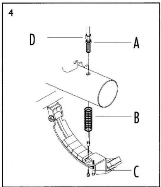

natural_image
Technical line drawing of a mechanical device with lever and base components (no text or symbols)
natural_image
Technical line drawing of a mechanical device with attached components and mounting holes (no text or symbols)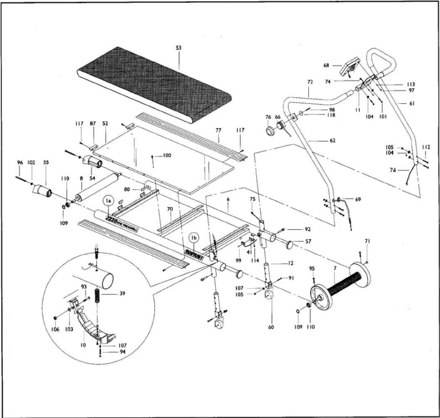
Ref. no Part no
| 6 | 103 4010 (incl. 70, 80) |
| 7 | 523 4018(incl. 31 - 34, 38, 108 - 110) |
| 8 | 523 4019(incl. 35 - 37, 109, 110) |
| 10 | 373 4002 (incl. 42) |
| 11 | 503 4014 |
| 12 | 103 4011 |
| 39 | 643 4002 |
| 41 | 503 4015 |
| 52 | 433 4012 (incl. 70) |
| 53 | 443 4006 |
| 54 | 533 4022 |
| 55 | 533 4023 |
| 57 | 533 4024 |
| 60 | 533 4025 |
| 61 | 203 4006 L (incl. 72) |
| 62 | 203 4007 R (incl.72) |
| 66 | 373 4003 |
| 68 | 233 4010 |
| 69 | 533 4026 |
| 70 | 533 4027 |
| 71 | 403 4034 |
| 72 | 213 4006 |
| 74 | 403 4035 (incl. 75) |
| 76 | 533 4028 |
| 77 | 433 4013 |
| 80 | 533 4029 |
| 87 | 433 4014 |
| 91 | 653 4014 |
| 92 | 663 4002 |
| 93 | 653 4015 |
| 94 | 653 4016 |
| 95 | 653 4017 |
| 96 | 653 4018 |
| 97 | 653 4019 |
| 98 | 653 4020 |
| 99 | 653 4021 |
| 100 | 653 4022 |
| 101 | 653 4023 |
| 102 | 653 4027 |
| 103 | 653 4028 |
| 104 | 653 4029 |
| 105 | 653 4032 |
| 106 | 653 4033 |
| 107 | 653 4034 |
| 109 | 673 4003 |
| 110 | 523 4020 |
| 112 | 653 4024 |
| 113 | 653 4030 |
| 114 | 653 4025 |
| 117 | 653 4026 |
| 118 | 653 4031 |
| - | 553 4002 Hardware kit |
| - | 423 4035 Decal set |
| - | 556 0003 Screw - shaped |
| - | 556 032 00 Allen key 6mm |
| - | 583 4012 Owners manual |


- ECB TREADMILL J 220
- REMARKS AND WARNINGS
- THE EQUIPMENT HAS BEEN DESIGNED FOR DOMESTIC USE, FOR WHICH THE FULL TUNTURI WARRANTY APPLIES.
- ASSEMBLY
- MOUNTING THE SUPPORT FEET
- MOUNTING THE HANDLEBARS
- NOTE!
- MOUNTING THE RESISTANCE ADJUSTMENT MECHANISM
- MOUNTING THE METER
- USE
- ADJUSTING RESISTANCE
- ADJUSTING INCLINE
- METER
- KEYS AND FUNCTIONS
- SPEED
- DISTANCE
- MODE
- KCAL
- TIME
- SET
- START/STOP
- SCAN (text "SCAN" on display)
- SETTING VALUES
- CHANGING BATTERIES
- MAINTENANCE
- ADJUSTING THE BELT ALIGNMENT
- ADJUSTING THE BELT TENSION
- CLEANING AND LUBRICATION OF THE BELT
- CLEANING THE TREADMILL
- TRANSPORT AND STORAGE
- DIMENSIONS
Marke : TUNTURI
Modell : J220
Kategorie : Laufband