IC5000 - Ladegerät Projecta - Kostenlose Bedienungsanleitung
Finden Sie kostenlos die Bedienungsanleitung des Geräts IC5000 Projecta als PDF.


Benutzerfragen zu IC5000 Projecta
0 Frage zu diesem Gerät. Beantworten Sie die, die Sie kennen, oder stellen Sie Ihre eigene.
Eine neue Frage zu diesem Gerät stellen
Laden Sie die Anleitung für Ihr Ladegerät kostenlos im PDF-Format! Finden Sie Ihr Handbuch IC5000 - Projecta und nehmen Sie Ihr elektronisches Gerät wieder in die Hand. Auf dieser Seite sind alle Dokumente veröffentlicht, die für die Verwendung Ihres Geräts notwendig sind. IC5000 von der Marke Projecta.
BEDIENUNGSANLEITUNG IC5000 Projecta
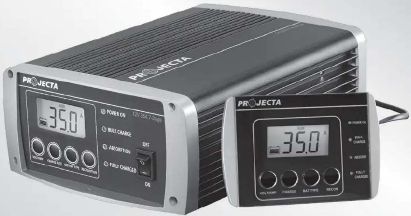
INTELLI-CHARGE
BATTERY CHARGER
7 STAGE SWITCHMODE
text_image
PROJECTA POWER ON 12V 35A 7-Stage BULK CHARGE ABSOLUTION FULLY CHARGED ON 35.0 A VOLT/AMP CHARGE RATE METER TYPE RECONDITION PROJECTA POWER ON BULK CHARGE ABSORES FULLY CHARGED 35.0 A VOLT/AMP CHARGE BATTYPE RECONIMPORTANT SAFETY INFORMATION
Please read this manual thoroughly before use and store in a safe place for future reference.
WARNING
- Explosive gases may escape from the battery during charging. Prevent flames and sparks. Provide adequate ventilation.
- Before charging, read the instructions.
- For indoor use. Do not expose to rain.
- For charging lead acid batteries ONLY (for the size and voltage specified in the specifications table).
- Disconnect the 240V mains supply before making or breaking the connections to the battery.
- The battery charger must be plugged into an earthed socket-outlet.
- Connection to supply mains is to be in accordance with National wiring rules.
- Do not attempt to charge non-rechargeable batteries.
- Never charge a frozen battery.
- If the AC cord is damaged do not attempt to use. It must be replaced or repaired by a qualified person.
- Corrosive substances may escape from the battery during charging and damage delicate surfaces. Store and charge in a suitable area.
- Ensure all vehicle accessories including lights, heaters, appliances etc are turned off prior to charging.
- This charger is not intended for use by persons (including children) with reduced physical, sensory or mental capabilities, or lack of experience and knowledge, unless they have been given supervision or instruction concerning use of the appliance by a person responsible for their safety.
- Young children should be supervised to ensure that they do not play with the appliance.
7-STAGE AUTOMATIC CHARGING
This is a fully automatic battery charger with 7 charge stages.
Automatic charging protects your battery from being overcharged so you can leave the charger connected to the battery indefinitely.
7-stage charging is a very comprehensive and accurate charging technique that gives your battery longer life and better performance compared to using traditional chargers.
Projecta's Intelli-Charge chargers can be adjusted to suit a number of different battery types including GEL, AGM, WET and Calcium. The chargers can also help restore drained and sulphated batteries.
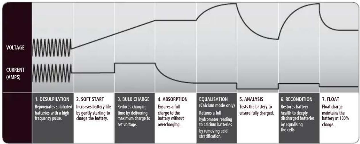
The 7 charge stages are:
Desulphation; Soft Start; Bulk; Absorption; Analysis; Recondition and Float.
flowchart
graph LR
    A["VOLTAGE"] --> B["1. DESULPHATION\nRejuvenates sulphated batteries with a high frequency pulse."]
    C["CURRENT (AMPS)"] --> D["2. SOFT START\nIncreases battery life by gently starting to charge the battery."]
    D --> E["3. BULK CHARGE\nReduces charging time by delivering maximum charge to set voltage."]
    E --> F["4. ABSORPTION\nEnsures a full charge to the battery without overcharging."]
    F --> G["EQUALISATION\n(Calcium mode only)\nReturns a full hydrometer reading to calcium batteries by removing acid stratification."]
    G --> H["5. ANALYSIS\nTests the battery to ensure fully charged."]
    H --> I["6. RECONDITION\nRestores battery health to deeply discharged batteries by equalising the cells."]
    I --> J["7. FLOAT\nFloat charge maintains the battery at 100% charge."]
DESULPHATION
The Desulphation stage is designed to break down sulphation occurring in batteries that have been left flat for extended periods of time, returning them back to full charge. Sulphation occurs when lead-sulphate hardens and clogs up the battery cells.
SOFT START
This is a preliminary charge process that gently introduces power to the battery, protecting the battery and increasing battery life.
BULK (CONSTANT CURRENT)
The Bulk stage reduces charging time by charging the battery at the maximum rate (constant current) to a set voltage, at which point the battery is approximately 80% charged.
ABSORPTION (CONSTANT VOLTAGE)
The absorption stage charges the battery to 100% by adjusting the charge rate allowing the battery to absorb more power.
EQUALISATION (CALCIUM MODE ONLY)
Designed especially for calcium batteries, this stage returns calcium batteries to full service by removing acid stratification of the electrolyte.
ANALYSIS
The analysis mode tests the battery to ensure that it has taken the charge; if the battery passes the test the charger will proceed to the float stage, but if the battery fails the test, the charger will apply a recondition charge to try to return the battery to full charge.
RECONDITION
If after charging, the battery is unable to hold the charge the battery reconditioning function is initiated automatically. This is most likely to take place on batteries that have been deeply discharged, prior to charging. The Recondition mode will then run for 4 hours and at the end will retest the battery. The Intelli-Charge battery charger will perform the recondition charge up to 3 times before switching the charging cycle to Float with an error indication.
FLOAT
The Float stage maintains the battery at 100% charge without overcharging or damaging the battery. This means the charger can be left connected to the battery indefinitely.
BATTERY CHEMISTRY SELECTION
The Multi-Chem function allows you to set the charging profile to suit each battery's chemistry type (GEL, AGM, WET and Calcium). This ensures correct and thorough charging and maximises battery performance and battery life. The following section describes the charge profiles for each chemistry type.
POWER SUPPLY (CONSTANT VOLTAGE OF 13.8 VOLTS)
This sets the charger in power supply mode giving a constant voltage of 13.8VDC. This mode is best used where appliances are drawing power from the battery, for example a Fridge.
GEL (MAX VOLTAGE OF 14.1 VOLTS)
This charge mode is designed for GEL batteries and has a maximum charge voltage of 14.1V. Note that some GEL batteries require a higher charge voltage such as 14.4V. The AGM mode can be used if this is required.
AGM (MAX VOLTAGE OF 14.4 VOLTS)
This charge mode is designed for AGM batteries and has a maximum charge voltage of 14.4V.
WET (BULK AND ABSORPTION 14.7 VOLTS, RECONDITION UP TO 16 VOLTS)
This charge mode is designed for WET batteries and has a maximum charge voltage of 14.7V during Bulk and Absorption stages and 16.0V during the Recondition stage.
CALCIUM (BULK AND ABSORPTION 14.7 VOLTS, EQUALISATION AND RECONDITION UP TO 16 VOLTS)
This charge mode is best suited for Calcium batteries that have been deeply discharged and require an equalisation charge to restore a full electrolyte reading. If the battery requires a simple ‘top-up’, the WET charge mode can be used.
FEATURES
ADJUSTABLE CHARGE RATE
The charger's output can be adjusted to suit the size of the battery for optimum charging.
REMOTE CONTROL DISPLAY\*
Control and monitor the charger's performance from a remote control display, allowing the charger to be flush or surface mounted out of the way and out of sight. The battery charger and remote are synchronised for operation either locally or by remote.
RUBBER END CAPS (IC2500W ONLY)
Protective rubber moulded end caps for the toughest workshop conditions.
TEMPERATURE COMPENSATION\*
The temperature sensor monitors the battery temperature and adjusts (compensates) the charger's output to prevent overcharging. This is ideal for batteries used in warmer climates or environments.
SWITCHMODE TECHNOLOGY
LCD SCREEN & LED INDICATORS
POLARITY PROTECTION
OVER TEMPERATURE PROTECTION
MOUNTING INSTRUCTIONS
MOUNTING BATTERY CHARGER
Intelli-Charge chargers are designed for indoor, out of weather use only. Ensure that both charger and battery are in a well-ventilated space during charging.
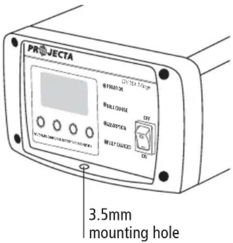
The battery charger end plates include a mounting flange for easy mounting. If permanently fixed the charger should be mounted to a suitable horizontal or vertical panel, with at least 10cm clearance from the end plates to provide adequate ventilation for the cooling fan.
text_image
PROJECTA 3.5mm mounting holeMOUNTING REMOTE CONTROL
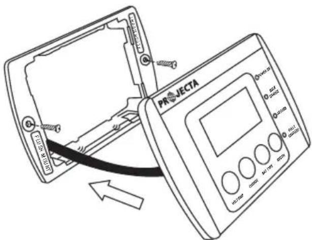
FLUSH MOUNT
- Cut a 93mm x 70mm hole into the desired mounting surface to suit the supplied mounting plate.
- Position the mounting plate into the hole with the side labelled 'FLUSH MOUNT' facing outwards and screw the supplied screws into the mounting surface as per the below illustration.
- Clip the remote control into the mounting bracket.
text_image
PROJECTA AU/100 AU/175 AU/240 AU/280 AU/320 AU/360 AU/400 AU/440 AU/480 AU/520 AU/560 AU/600 AU/640 AU/680 AU/720 AU/760 AU/800 AU/840 AU/880 AU/920 AU/960 AU/1000SURFACE MOUNT
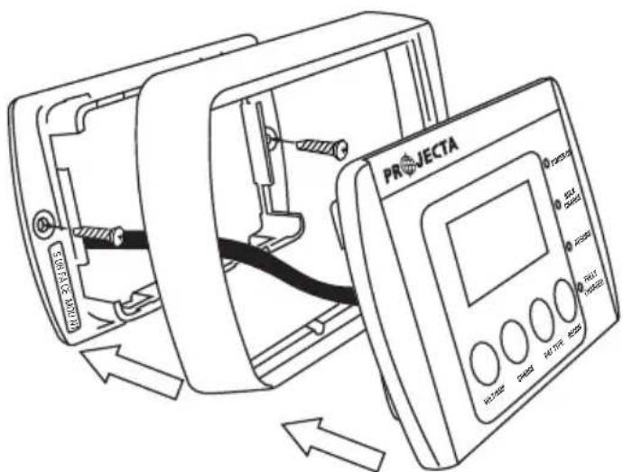
- Position the supplied mounting plate onto the desired mounting surface so the side labelled 'SURFACE MOUNT' is facing outwards and screw the supplied screws into the mounting surface as per the below illustration.
- Drill a 15mm cable exit hole into the mounting surface, ensure cable exit hole is positioned directly in the middle of the mounting plate.
- Position the remote control into the remote control surround as per the below illustration and clip into the mounting bracket.
text_image
PROJECTA PORTS PORTS PORTS PORTS PORTS PORTS PORTS PORTS PORTS PORTS PORTS PORTS PORTS PORTS PORTS PORTS PORTS PORTS PORTS PORTS PORTS PORTS PORTS PORTS PORTS PORTS PORTS PORTS PORTS PORTS PORTS PORTS PORTS PORTSREMOVING REMOTE CONTROL
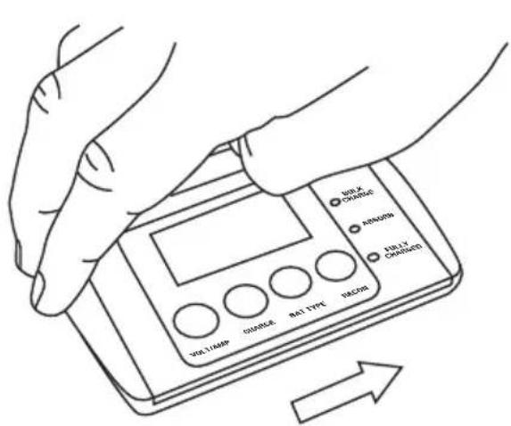
FLUSH MOUNT
- Pull the remote control sideways and firmly lift
- The remote will click out of place
text_image
NO. X CHARGE ARAGON FULLY CHARGED NO.11AMP CHARGE BAT TYPE BEGR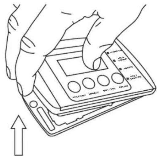
text_image
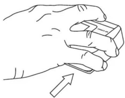
PROMO ON MILE CANCE AVOCING POLY CHARGED MOYA CHARGE CHARGE GAT-TYPE REGIONSURFACE MOUNT
- Holding the remote on either side, push upwards.
- Squeeze the sides together to lift away.
natural_image
Line drawing of a hand holding an eraser with an arrow indicating motion (no text or symbols)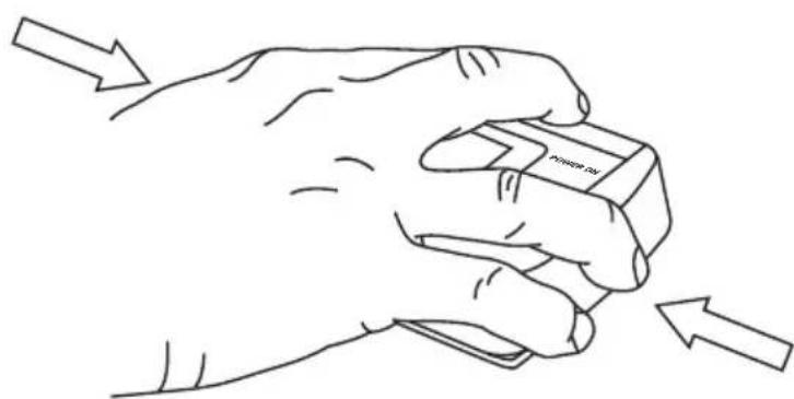
natural_image
Line drawing of a hand holding a device with directional arrows indicating movement (no text or symbols)CONTROLS
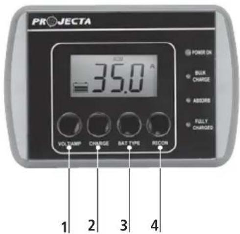
The battery charger and remote control* interfaces are synchronised and identical in operation allowing you to monitor the battery charger's performance and customise the charge settings to best suit your battery. The function of each button is explained below:
- VOLT/AMP: Change LCD screen display from battery voltage to input current
- CHARGE RATE: Set the charge rate to suit the size of the battery
- BATTERY TYPE: Set the charging profile to suit the battery's chemistry type
- RECONDITION: Initiate recondition mode
*Remote not included with IC2500W
text_image
PROJECTA 35.0 A VOLTAMP CHARGE BAT TYPE RICON POWER ON BLUX CHARGE ABSORS FULLY CHARGED 1 2 3 4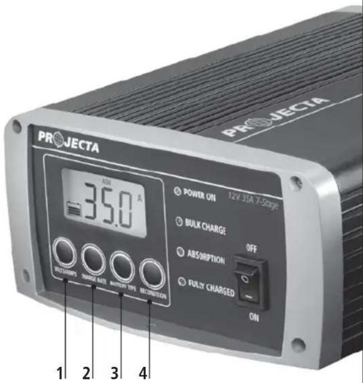
text_image
PROJECTA 35.0 A POWER ON 12V 35A 7-Stage BULK CHARGE ABSORPTION OFF FULLY CHARGED ON 1 2 3 4LED CHARGE INDICATORS
BATTERY CHARGER & REMOTE CONTROL\*
These battery chargers include coloured LEDs that illuminate various signals to indicate different stages of charging.
| LED LED SIGNAL & STAGES OF CHARGING | |||||||
| Desulphation Equalisation | Soft Start | Bulk | Absorption/ | Analysis | Recondition | Float | |
| Bulk Charge (Blue) | Fast Flash | Slow Flash | Solid On | - | - | Slow Flash | - |
| ---- | --- | —— | --- | ||||
| Absorption (Blue) | - | - | - | Solid On | Slow Flash | Slow Flash | - |
| —— | --- | --- | |||||
| Fully Charged (Green) | - | - | - | - | - | - | Solid On |
| Power On (Red) | Solid On: NormalFlashing: Fault (See Faults & Errors, page 16) | ||||||
CHARGING INSTRUCTIONS
STEP 1 - CHECK THE ELECTROLYTE LEVEL
Prior to charging the battery, remove the vent caps and check the electrolyte level (not required on sealed & maintenance free batteries). The electrolyte should be 6mm (1/4") above the battery's plates. If low, top up with distilled water to the correct level and refit the vent caps.
STEP 2 - CONNECT TO BATTERY
There are three options for connecting to battery.
Step 2A – Connecting to a battery that is out of the vehicle
Step 2B – Connecting to a battery fitted to a vehicle
Step 2C – Permanent hard wiring connection to a battery
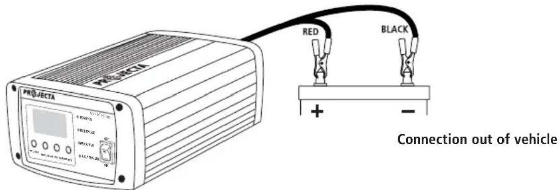
STEP 2A – BATTERY OUT OF VEHICLE
Connect the RED lead (battery clip) from the charger to the Positive (+) battery post. Connect the BLACK lead (battery clip) from the charger to the Negative (-) battery post.
text_image
PROJECTA RED BLACK Connection out of vehicleSTEP 2B – BATTERY IN VEHICLE
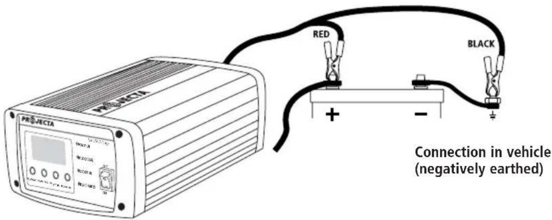
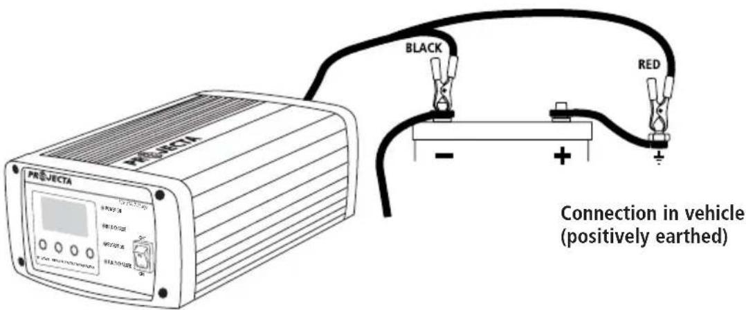
Determine if the vehicle is Positively (+) or Negatively (-) earthed. Negatively earthed vehicles have a cable (usually black) from the Negative battery terminal to the vehicle's chassis.
Negatively earthed (most vehicles)
Connect the RED lead (battery clip) from the charger to the Positive (+) battery terminal.
Connect the BLACK lead (battery clip) from the charger to the vehicle's chassis away from the fuel line or moving parts.
text_image
PROJECTA RED BLACK Connection in vehicle (negatively earthed)Positively earthed
Connect the BLACK lead (battery clip) from the charger to the Negative (-) battery terminal.
Connect the RED lead (battery clip) from the charger to the vehicle's chassis away from the fuel line or moving parts.
text_image
PROJECTA BLACK RED Connection in vehicle (positively earthed)STEP 2C – PERMANENT HARD WIRING
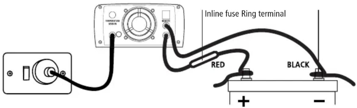
It is possible to hardwire the DC charging leads to the battery for permanent installations.
The DC leads are pre-wired with cable lugs to make this process easier.
It is recommended to fit a circuit breaker or inline fuse with the following ratings. (See below)
$$ \mathrm{IC2500} \& \mathrm{IC2500W} = 3 0 \mathrm{Amp} $$
$$ \mathrm{IC3500} = 5 0 \mathrm{Amp} $$
$$ \mathrm{IC5000} = 1 0 0 \mathrm{Amp} $$
$$ \mathrm{IC800-24=12Amp} $$
Connection:
- Unscrew and remove the battery clips from the DC leads using a 4mm allen key.
Note: These battery chargers include sensor wires that run parallel to both the positive and the negative DC leads. This allows for accurate voltage measurements to be taken directly from the battery. It is strongly recommended not to cut the DC leads during installation. However if the DC leads are cut, ensure that the sensor wires are included in both positive and negative connections. - Connect a circuit breaker or inline fuse to the RED Positive (+) lead (include sensor wire if DC lead has been cut).
- Connect a short cable to the other end of the circuit breaker or inline fuse & connect to the Positive (+) battery post.
- Connect the cable lug fitted to the BLACK lead to the Negative (-) battery post (include sensor wire if DC lead has been cut).
- Fit the correctly rated fuse (inline fuse applications only).
text_image
Temperature Sensor TRENGTH RANGE Inline fuse Ring terminal RED BLACKIf the charger is used in a Permanent/Hard Wired application and the vehicle will not be used for some time, it is best to leave the charger connected to mains power (turned 'On') so that it can maintain the battery fully charged.
Ensure any modification to the 240V mains lead is carried out by a qualified person and that connection to supply mains is in accordance with National wiring rules.
STEP 3 – REMOTE CONTROL\* & TEMPERATURE SENSOR\* (OPTIONAL)
If you require the temperature sensor and remote control, install before connecting the charger to 240V mains power. These accessories are optional; the charger will operate normally with or without accessories being fitted.
To install the remote control, insert the data plug into the data socket at the rear of the battery charger.
Cable length: 4.5 metres.
Warning: Ensure the cable is secured safely away from moving parts.
Installing Temperature Sensor
To install the temperature sensor, insert the plug into the temperature sensor socket at the rear of the battery charger. Install the ring terminal to the negative battery terminal.
Cable length: 1.8 metres
Warning: Ensure the cable is secured safely away from moving parts.
STEP 4 - CONNECT TO 240V MAINS POWER
Connect the battery charger to the 240V mains powered socket and turn on the mains power. Turn battery charger On/Off switch to on.
STEP 5 – SET CHARGE RATE
The charge rate should be set according to the size of the battery. See the recommended charge rates for various battery sizes in the table below.
(Not all outputs are available on all models)
a. Press the CHARGE RATE button. The LCD screen will flash the present setting.
b. Press the CHARGE RATE button repeatedly until desired setting is displayed.
c. Wait for the LCD screen to stop flashing.
Note: Failure to wait for the screen to stop flashing will cause the charge rate to default to previous setting.
ADJUSTABLE CHARGE RATES: 12 VOLT BATTERIES
| CHARGE RATE BATTERY SIZE (12V) | |||||
| Deep Cycle (AH) | Automotive (CCA) | Marine (MCA) | Time (Hours) | ||
| 2 Amp | 14–40 | 80–240 110–330 | 7–24 | ||
| 6 Amp | 40–120 | 240–720 | 330–1000 | 7–24 | |
| 8 Amp | 60–160 | 360–1000 | 500–1300 | 7–24 | |
| 12 Amp | 80–240 | 480–1440 | 660–2000 | 7–24 | |
| 16 Amp | 110–320 | 660–1900 | 930–2700 | 7–24 | |
| 25 Amp | 170–500 | 1000–3000 | 1400–4200 | 7–24 | |
| 35 Amp | 240–700 | 1440–4200 | 2000–5800 | 7–24 | |
| 50 Amp | 350–1000 | 2100–6000 | 2900–8300 | 7–24 | |
ADJUSTABLE CHARGE RATES: 24 VOLT BATTERIES
| CHARGE RATE BATTERY SIZE (24V) | |||||
| Deep Cycle (AH) Automotive (CCA) Marine (MCA) Time (Hours) | |||||
| 2 Amp 14–40 | 80–240 110–330 | 7–24 | |||
| 4 Amp | 30–80 180–480 250–650 | 7–24 | |||
| 6 Amp 40–120 | 240–720 | 330–1000 | 7–24 | ||
| 8 Amp | 60–160 | 360–1000 | 500–1300 | 7–24 | |
STEP 6 – SET BATTERY CHEMISTRY TYPE
Battery Chemistry should be selected by the type of battery being charged (refer to the battery manufacturer's specifications for battery type). Refer to pages 4 and 5 for a detailed explanation.
For example, if you are charging an AGM battery, then AGM mode will need to be selected. This can be done by the following procedure:
a. Press the BATTERY TYPE button. The LCD screen will flash the present setting.
b. Press the BATTERY TYPE button repeatedly until desired setting is displayed.
c. Wait for the LCD screen to stop flashing.
Note: Failure to wait for the screen to stop flashing will cause the charge rate to default to previous setting.
STEP 7 - CHARGING
During normal charging the LCD screen will default to the VOLTS display; to view input current press the VOLTS/AMPS button.
During Equalisation and Recondition, the LCD screen will display rapid horizontal lines.
STATUS LCD DISPLAY
| Equalisation (Calcium Only)Recondition (Auto) ---Recondition (Manual) Rapid horizontal (scrolling) lines | 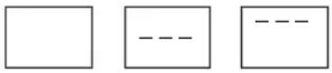 |
The LED indicators will also illuminate and flash various signals, indicating the different stages of charging. Refer to page 7 for a discription of LED signals.
When the battery is fully charged, the green FULLY CHARGED LED will illuminate. This is known as the float stage and the charger can be left connected to the battery without over charging.
If the red POWER LED is flashing, or the LCD screen displays an error signal, there is a fault; refer to the "Fault & Errors" explanation on page 15 of this manual.
STEP 8 - DISCONNECTION
Ensure the 240V mains switch is turned off and the charger is disconnected from the 240V mains power.
Battery out of vehicle
Remove the BLACK lead (battery clip) from the battery. Remove the RED lead (battery clip) from battery.
Battery in vehicle
Remove the chassis connection. Remove the battery terminal connection.
STEP 9 – CHECK THE ELECTROLYTE LEVEL (CALCIUM MODE ONLY)
Check the electrolyte level and top up if required.
INITIATING RECONDITION MODE
The recondition mode can restore batteries from a deeply discharged state by equalising the cells (equalisation charge) ensuring they are operating at full capacity. A recondition charge should be performed periodically to optimise the battery's health and performance.
STEP 1
Follow STEPS 1 to 6 of the "Charging Instructions" of this booklet.
Ensure the battery is removed from the vehicle to prevent the battery's electrolyte from spilling over and damaging the car or engine bay.
STEP 2 – PRESS THE RECONDITION BUTTON
The charger will be in this mode for 4 hours. During recondition the LCD screen will display rapid horizontal lines. Upon completion of the recondition, the charger will proceed to carry out a normal charge on the battery.
STEP 3
Follow STEPS 7 to 9 of the Charging Instructions of this booklet.
LOCKING THE REMOTE CONTROL
Locking the remote control will disable the CHARGE, BAT TYPE & RECON keys from use. This function is ideal for hire vehicles etc as it prevents the chargers settings from being altered if the keys are touched. When locked the VOLT/AMP key will still work to display the volts or amps.
To lock; press and hold the 'CHARGE' and 'BAT TYPE' keys for 3 seconds until you hear a beep. This indicates the keys are now locked.
To unlock; press and hold and 'CHARGE' and 'BAT TYPE' keys for 3 seconds until you hear another beep. This indicates the keys are now unlocked.
FAULTS & ERRORS
There are three error codes that may be displayed. These will be displayed in the following way:
| LCD Power On LED | Fault Remedy | ||
| Err Slow Flashing | Short circuit or reverse | connection of the clips | Check clips are not touching each other OR Check the clips are correctly connected to the battery |
| F01 Fast Flashing | Bulk charging has | timed out and stopped after 22 hours | Battery may be faulty |
| - Slow Flashing | The charger has | entered recondition mode 3 times and has timed out | Battery may be faulty and may need replacing OR There is a load on the battery causing the battery to fail Analysis |
| OTP Fast Flashing | The charger has | overheated and has switched off | Ensure adequate ventilation around the charger |
| OLC Fast Flashing | Sensor wires are not | connected to the positive/negative connections | If DC leads have been cut for hardwiring, check sensor wires are included in both positive & negative connections (Refer to page 13, point 1) |
| OCP Fast Flashing | The charger has | encountered an error | Contact Brown & Watson International |
SPECIFICATIONS
| P/No. IC2500 & IC2500W IC3500 IC5000 IC800-24 | |||||
| Type 7 stage 7 stage 7 stage 7 stage | |||||
| Input (nominal) 240VAC, 50Hz 240VAC, 50Hz 240VAC, 50Hz 240VAC, 50Hz | |||||
| Input Power 792W 1080W 1488W 480W | |||||
| Output Voltage 12V 12V 12V 24V | |||||
| Output Current 2, 6, 12, 25A 2, 8, 16, 35A 2, 6, 12, 25, 50A 2, 4, 6, 8A | |||||
| Minimum Start Voltage 2.5V 2.5V 2.5V 4.5V | |||||
| Back Drain 1mA 1mA 1mA 1mA | |||||
| CHARGE CONTROL | |||||
| Desulphation Pulse charge up to 11V High frequency Pulse charge up to 11V 24V | |||||
| Soft Start current up to 12V Half the rated set current up to 12V Half the rated set current up to 12V Half the rated set current up to 24V | |||||
| Bulk 14.1V (GEL), 14.4V (AGM), 14.7V (WET), 14.7V (CALCIUM) Set current up to: 14.1V (GEL), 14.4V (AGM), 14.7V (WET), 14.7V (CALCIUM) Set current up to: 14.1V (GEL), 14.4V (AGM), 14.7V (WET), 14.7V (CALCIUM) Set current up to: 28.2V (GEL), 28.8V (AGM), 29.4V (WET), 29.4V (CALCIUM) | |||||
| Absorption 2 Amp setting: 0.3A 2 Amp setting: 0.3A 2 Amp setting: 0.3A 2 Amp setting: 0.3A 2 Amp setting: 0.3A 2 Amp setting: 0.3A 2 Amp setting: 0.3A 2 Amp setting: 0.3A 2 Amp setting: 0.3A 2 Amp setting: 0.3A 2 Amp setting: 0.3B Amp setting: 0.9A 8 Amp setting: 1.2A 6 Amp setting: 0.9A 4 Amp setting: 0.6A 12 Amp setting: 1.8A 16 Amp setting: 2.4A 12 Amp setting: 1.8A 6 Amp setting: 0.9A 25 Amp setting: 3.75A 25 Amp setting: 3.75A 8 Amp setting: 1.2A 50 Amp setting: 7.5A | |||||
| Equalization (Calcium mode only) then hold for 1 hour or 12 hour timeout Constant current (2.0–3.75A) up to 16V then hold for 1 hour or 12 hour timeout Constant current (2.0–5.25A) up to 16V then hold for 1 hour or 12 hour timeout constant current (2.0–7.5A) up to 16V then hold for 1 hour or 12 hour timeout constant current (2.0–7.5A) up to 16V then hold for 1 hour or 12 hour timeout constant current (2.0–7.5A) up to 16V then hold for 1 hour or 12 hour timeout constant current (2.0–7.5A) up to 16V than hold for 1 hour or 12 hour timeout constant current (2.0–7.5A) up to 16V then hold for 1 hour or 12 hour timeout constant current (2.0–7.5A) up to 16V then hold for 1 hour or 12 hour timeout constant current (2.0–7.5A) up to 16V then hold for 1 hour or 12 hours | |||||
| Analysis Monitors battery for 90 sec | |||||
| Recondition (0.3–3.75A) for 4 hours limited to: 14.1V (GEL), 14.4V (AGM), 16.0V (WET), 16.0V (CALCIUM) | Constant current (0.3–5.25A) for 4 hours limited to: 14.1V (GEL), 14.4V (AGM), 16.0V (WET), 16.0V (CALCIUM) | Constant current (0.3–7.5A) for 4 hours limited to: 14.1V (GEL), 14.4V (AGM), 16.0V (WET), 16.0V (CALCIUM) | Constant current (0.3–1.2A) for 4 hours limited to: 28.2V (GEL), 28.8V (AGM), 32.0V (WET), 32.0V (CALCIUM) | Constant current | Constant current |
| Float 13.7V 13.7V 13.7V 27.4V | |||||
| POWER SUPPLY | |||||
| Set Voltage 13.8V 13.8 13.8V 27.6V | |||||
| Maximum Current 25A 35A 50A 8A | |||||
| BATTERY RANGE | |||||
| Deep Cycle 14–500Ah 14–700Ah 14–1000Ah 14–160Ah | |||||
| Automotive 80–3000CCA 80–4200CCA 80–6000CCA 80–1000CCA | |||||
| Marine 110–4200MCA 110–5800MCA 110–8300MCA 110–1300MCA | |||||
| Types of Batteries Most types of batteries including GEL, AGM, WET CELL and CALCIUM | |||||
| Size (mm) IC2500W: IC2500: 210 x 81 x 168 250 x 81 x 168 270 x 81 x 168 190 x 81 x 168 | |||||
| Weight IC2500W: IC2500: 2.0 kg 2.6 kg 3.0 kg 1.8 kg | |||||
PRODUCT OVERVIEW
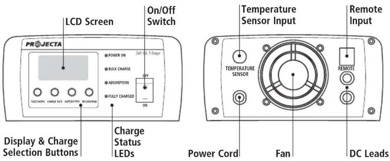
text_image
LCD Screen On/Off Switch PROJECTA 24V/84.7-Stage POWER ON BULK CHARGE ABSORPTION FULLY CHARGED OFF ON VOLTCHAMPS CHANGE RATE BATTERYTYPE SECONITION Display & Charge Selection Buttons Charge Status LEDs Temperature Sensor Input Remote Input TEMPERATURE SENSOR Power Cord Fan DC Leads REMOTEIC2500 IC2500WIC800-24
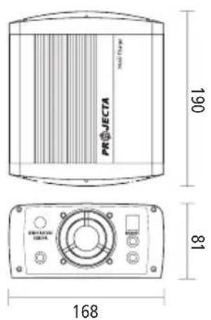
text_image
PROJECTA 190 81 168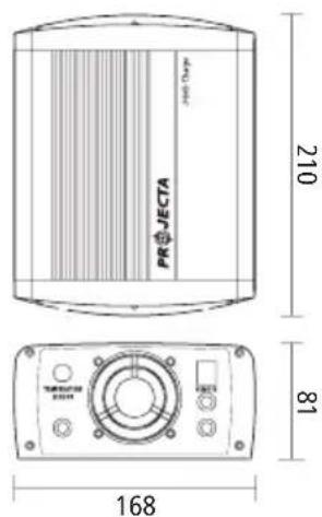
text_image
PROJECTA 210 81 168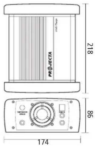
text_image
PROJECTA and Charge 218 86 174IC5000IC3500
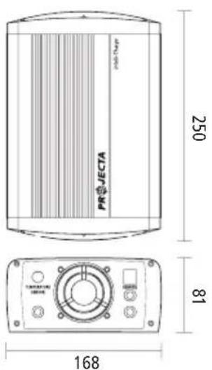
text_image
PROJECTA 250 81 168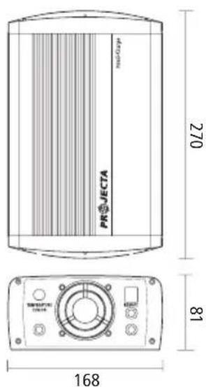
text_image
PROJECTA 270 81 168FREQUENTLY ASKED QUESTIONS
Q. How do I know if the battery is charged?
A. The charger's FULLY CHARGED LED will illuminate (solid) and the remote's bi-colour LED will illuminate green (solid). Alternatively use a Battery Hydrometer (Projecta Part No. BH100). A reading of 1.250 or more in each cell indicates a fully charged battery.
Q. I have connected the charger properly but the LCD display reads 0.0 (zero) Volts and does not appear to be charging.
A. In some cases batteries can be flattened to the point where they have very little or no voltage. This can occur if a small amount of power is used for a long time, for example a map reading light is left on for a week or more. Projecta 7 Stage chargers are designed to charge from as little as as little as 2.5 Volts (12V) or 4.5 Volts (24V).
If the voltage is lower than the voltages stated above use a pair of booster cables to connect between two batteries to provide more than 2.5 Volts (12V) or 4.5 Volts (24V) to the battery being charged. The charger can then start to charge the battery and the booster cables can be removed.
Q. Can I use the charger as a power supply
A. Power Supply mode is designed to operate as a float charge to maintain a battery when running a load or appliance from the battery. Power Supply will only operate when connected to a battery.
Q. How can I tell what stage the battery charger is in?
A. The LCD screen and coloured LEDs indicate the various stages of charging. Refer to pages 7 ("LED Charge Indicators") and 13 ("Charging Instructions – Step 7") of this booklet.
Q. What happens if my battery charger is in Desulphation mode or Soft Start mode, but I want to start bulk charging?
A. Desulphation mode is time limited to 6 hours and Soft Start is limited to 1 hour. If you can not wait for the battery charger to move through these stages you can select Power Supply mode to charge the battery. After an hour of charging in Power Supply mode, there should be sufficient charge in the battery to bypass both Desulphation and Soft Start. Select the correct battery chemistry type to continue charging the battery. Whilst in Power Supply mode the charger will output a full current up to 13.8 Volts (12V) or 27.6 Volts (24V).
Q. What if I have an appliance connected to the battery whilst charging?
A. Powering an appliance while charging your battery will impact on the battery chargers ability to accurately measure the battery's response to the charge being applied. The battery charger has been designed to accommodate this situation although not recommended.
For optimum charging it is recommended to charge without any appliance load on the battery. Power Supply mode is recommended when an appliance is connected to a battery and is drawing power.
Q. Can I select a different battery chemistry for charging my battery?
A. Yes the battery chemistry selection can be different to your battery type if the charge voltages match the battery manufacture's recommendations.
Q. Why does CALCIUM mode take so long to charge?
A. To fully charge a Calcium battery, the battery requires an extra charging stage called 'Equalisation'. This consists of a constant current being fed into the battery until 16 Volts (12V) or 32 Volts (24V) is reached. This rejuvenates the battery cells. This charging stage can take up to 12 hours.
Q. Why do I need a special Calcium mode?
A. Because of the different chemistry used to make a Calcium battery, a different charging algorithm (or technique) is required. Calcium batteries are also affected when deeply discharged or used heavily. They need to be recharged by a Calcium charger to fully recharge the battery and to maximize the battery's life and performance.
Q. What is a Calcium battery?
A. Calcium batteries are lead acid batteries that have had calcium added to the lead plates, either to one plate (called Calcium Hybrid) or to both plates (called Calcium–Calcium).
The added calcium provides a number of benefits:
i. Lower internal resistance which provides a small increase in CCA performance.
ii. The ability to withstand higher engine bay temperatures.
iii. Low self discharge rate, which increases the shelf life, typically 4 times longer than a Lead–Lead battery.
NOTES:
WARRANTY STATEMENT
Applicable only to product sold in Australia
Brown & Watson International Pty Ltd of 1500 Ferntree Gully Road, Knoxfield, Vic., telephone (03) 9730 6000, fax (03) 9730 6050, warrants that all products described in its current catalogue (save and except for all bulbs and lenses whether made of glass or some other substance) will under normal use and service be free of failures in material and workmanship for a period of one (1) year (unless this period has been extended as indicated elsewhere) from the date of the original purchase by the consumer as marked on the invoice. This warranty does not cover ordinary wear and tear, abuse, alteration of products or damage caused by the consumer.
To make a warranty claim the consumer must deliver the product at their cost to the original place of purchase or to any other place which may be nominated by either BWI or the retailer from where the product was bought in order that a warranty assessment may be performed. The consumer must also deliver the original invoice evidencing the date and place of purchase together with an explanation in writing as to the nature of the claim.
In the event that the claim is determined to be for a minor failure of the product then BWI reserves the right to repair or replace it at its discretion. In the event that a major failure is determined the consumer will be entitled to a replacement or a refund as well as compensation for any other reasonably foreseeable loss or damage.
This warranty is in addition to any other rights or remedies that the consumer may have under State or Federal legislation.
IMPORTANT NOTE
Our goods come with guarantees that cannot be excluded under the Australian Consumer Law. You are entitled to a replacement or refund for a major failure and compensation for any other reasonably foreseeable loss or damage. You are also entitled to have the goods repaired or replaced if the goods fail to be of acceptable quality and the failure does not amount to a major failure.
Distributed by
AUSTRALIA
Brown & Watson International Pty Ltd
Knoxfield, Victoria 3180
Telephone (03) 9730 6000
Facsimile (03) 9730 6050
National Toll Free 1800 113 443
NEW ZEALAND
Narva New Zealand Ltd
22–24 Olive Road
PO Box 12556 Penrose
Auckland, New Zealand
Telephone (09) 525 4575
Facsimile (09) 579 1192