DBC100 - Nicht kategorisiert Projecta - Kostenlose Bedienungsanleitung
Finden Sie kostenlos die Bedienungsanleitung des Geräts DBC100 Projecta als PDF.


Benutzerfragen zu DBC100 Projecta
0 Frage zu diesem Gerät. Beantworten Sie die, die Sie kennen, oder stellen Sie Ihre eigene.
Eine neue Frage zu diesem Gerät stellen
Laden Sie die Anleitung für Ihr Nicht kategorisiert kostenlos im PDF-Format! Finden Sie Ihr Handbuch DBC100 - Projecta und nehmen Sie Ihr elektronisches Gerät wieder in die Hand. Auf dieser Seite sind alle Dokumente veröffentlicht, die für die Verwendung Ihres Geräts notwendig sind. DBC100 von der Marke Projecta.
BEDIENUNGSANLEITUNG DBC100 Projecta
12 VOLT
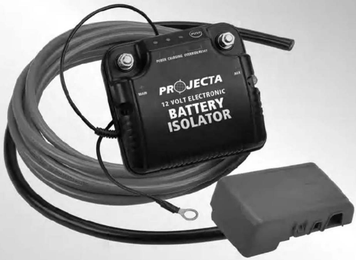
ELECTRONIC DUAL BATTERY ISOLATOR
text_image
POWER CHARGING OVERRIDE/RESET PROJECTA 12 VOLT ELECTRONIC BATTERY ISOLATOR MAIN ALEXWARNING
- PLEASE READ THESE INSTRUCTIONS COMPLETELY PRIOR TO INSTALLATION.
- BATTERIES PRODUCE EXPLOSIVE GASES – Ensure no sparks or flames are present.
- Wear eye protection.
- Vehicles must be in "NEUTRAL" or "PARK", park brakes "ON"
- Follow all vehicle manufacturer's instructions.
- Beware of moving parts.
- Battery Isolators are designed for negative ground alternator systems with batteries of the same nominal voltage.
- Batteries of differing voltages cannot be used.
FEATURES
- Easy to Install – The electronic isolator does not require any changes to the vehicle's existing wiring. It can be fitted to all 12V vehicle types.
- Priority Charging for Starting Battery – Ensures that the starting battery is fully charged before connecting the auxiliary battery in parallel.
- Manual Override – If the starting battery is flattened and the auxiliary battery is charged, the electronic isolator allows the batteries to be manually paralleled to jumpstart the vehicle.
- Over-Current Protection – Protects the Isolator and charging system from over current damage, which could occur due to a short circuit in the wiring.
- Surge Protection – Provides surge protection for vehicles with electronic ignition/management systems.
SPECIFICATIONS
| PART NO. DBC100 DBC150 | ||
| VOLTAGE 12V 12V | ||
| CHARGING CURRENT 75A/100A peak 125A/150A peak | ||
| CHARGE TYPE Parallel Parallel | ||
| CONTROL Electronic Electronic | ||
| MOUNTING Surface/firewall/battery side Surface/firewall/battery side | ||
| CURRENT DRAW | Charging 500mA(Standby 30mA) (Standby 30mA) | Charging 500mA |
| VOLTAGE DROP | None | None |
| SURGE PROTECTION | Built in | Built in |
ITEMS NEEDED
If you have purchased the Projecta Electronic Isolator (P/No. DBC100 or DBC150) you will also need:
- Charged auxiliary battery – Deep cycle recommended for most applications
• Auxiliary battery cradle & battery clamp - Battery terminals & lugs
• 150A fuse or circuit breaker - Battery cable
- 14mm ^2 (6 B&S) minimum for engine bay mounted auxiliary batteries (up to 3m)
- 20mm ^2 (4 B&S) for rear of vehicle / trailer mounted auxiliary batteries
If you have purchased the Projecta Electronic Dual Battery System (P/No. DBC100K, DBC150K or DBC150TK) you will only need:
- Charged auxiliary battery – Deep cycle recommended for most applications
• Auxiliary battery cradle & battery clamp
For all 'dual battery systems', follow the instruction supplement included in the kit.
INSTALLATION - MOUNTING
- Disconnect the negative battery cable (Earth) from the vehicle's starting battery.
Note: To prevent the loss of vehicle electronic memories, radio presets & security codes, it is recommended that an "Electrical System Memory Protector" be used.
- Mount the auxiliary battery cradle and fit the auxiliary battery.
- Mount the electronic isolator in a convenient location as near to the main battery as possible and no further than 3m. Keep the isolator as far as possible from the exhaust manifold, turbo or any other high temperature components. Do not mount on the engine.
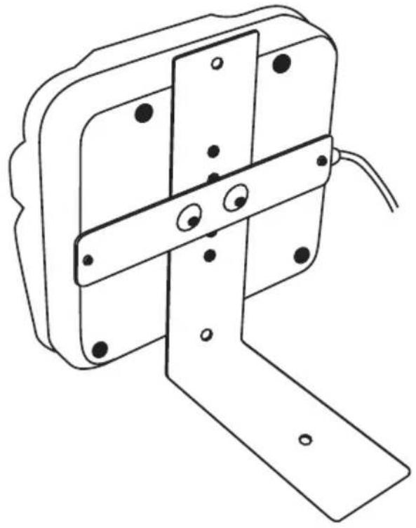
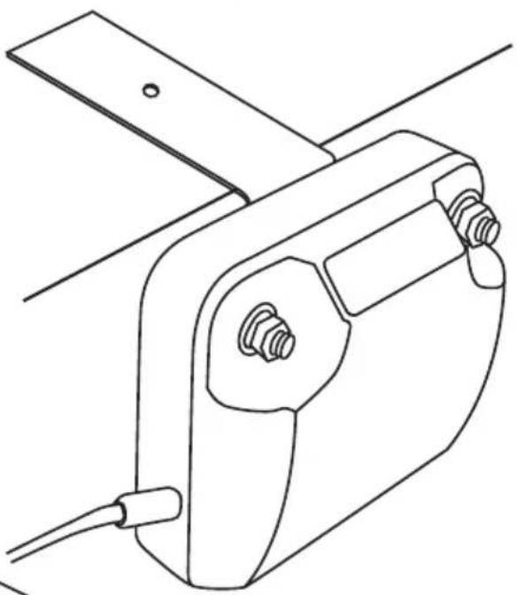
'L' bracket mounting – The 'L' bracket is fitted to the rear of the isolator. Once attached to the isolator the bracket can be fastened to the vehicle using screws/bolts or slipped under the battery for battery side mounting.
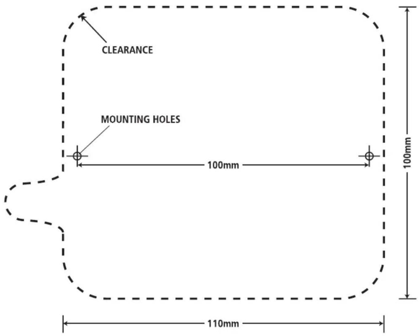
Surface mounting – Using the supplied template (page 11), select a location which offers a flat plastic or thin metal surface to mount, mark and drill 2 x 2mm (5/64") holes and mount the isolator with the screws provided.
"L" BRACKET ATTACHMENT
natural_image
Technical line drawing of a mechanical bracket with mounting holes and a central support (no text or symbols)"L" BRACKET MOUNTING (Bracket can be bent to shape to suit the vehicle)
natural_image
Line drawing of a mechanical clamp or bracket device with two screws and a cable (no text or symbols)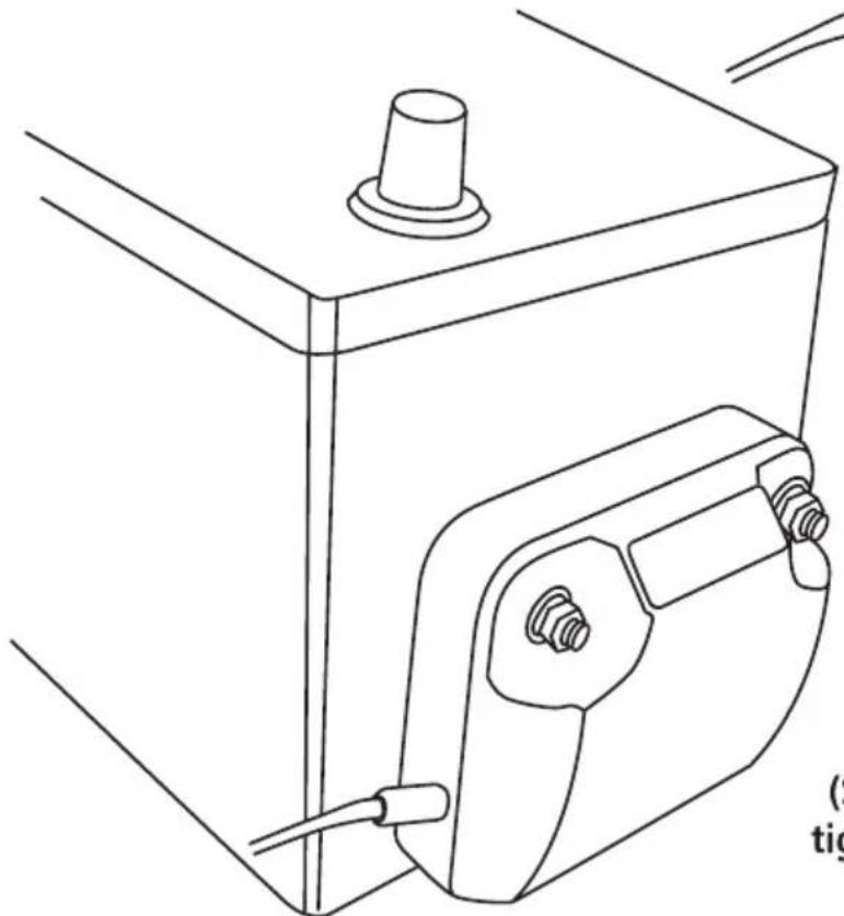
natural_image
Line drawing of a mechanical component with a cylindrical top and attached electrical connector (no text or symbols)BATTERY SIDE MOUNTING
(Slip "L" Bracket under battery and tighten the battery hold down clamp)
INSTALLATION - CONNECTION
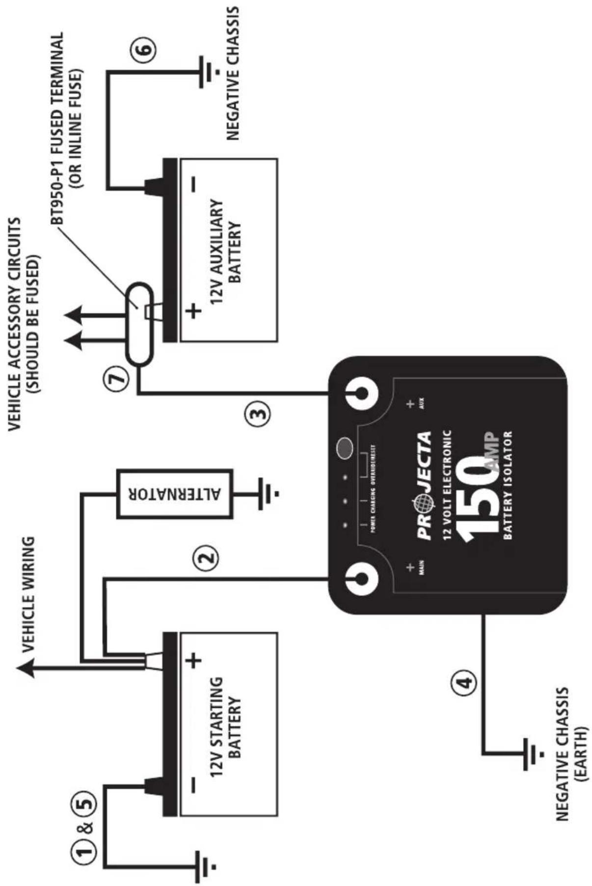
To make the electrical connections, the supplied battery cables will need to be made to the correct length using cable lugs and heatshrink. Cable lugs should be crimped or soldered to the stripped battery cable and then protected with the heatshrink.
- Disconnect the negative battery cable (Earth) from the vehicle's starting battery.
Note: To prevent the loss of vehicle electronic memories, radio presets & security codes, it is recommended that an "Electrical System Memory Protector" be used. - Connect a length of the supplied red cable from the 'MAIN' (+) terminal on the isolator to the positive battery terminal on the starting (main).
- Connect a length of the supplied red cable from the 'AUX' (+) terminal on the isolator to the positive battery terminal of the auxiliary battery. The connection at the Auxiliary battery should be fused using a Projecta 'Fused' battery terminal (P/No.BT950-P1) or a 150 Amp fuse or circuit breaker mounted inline. If using the BT950-P (Fused distribution terminal) the connection from the battery isolator should be made to main (large) fuse stud.
Do not over-tighten the terminal studs on the electronic isolator. - Connect the isolator's 'Earth' wire (small black wire with ring terminal) to a suitable chassis bolt or screw, ensure the ring terminal will make a good electrical connection by removing any paint.
- Reconnect the starting (main) battery's negative cable (Earth), the isolator should now flash the red 'power' LED.
- Connect a length of the supplied black cable from the vehicle's chassis or engine block to the negative terminal of the auxiliary battery as a ground cable (Earth), the isolator should now show a solid red 'power' LED.
- Connect all of the auxiliary loads (phone, lights, stereo, refrigerator, etc.) to the positive battery terminal of the auxiliary battery, use appropriate circuit protection fuses, if using the Projecta BT950-P1 terminal this includes 2 x 30A fused accessory circuits.
NUMBERS REFER TO THE STEPS IN THE INSTRUCTION TEXT
text_image
VEHICLE WIRING VEHICLE ACCESSORY CIRCUITS (SHOULD BE FUSED) 12V STARTING BATTERY ALTERNATOR BT950-P1 FUSED TERMINAL (OR INLINE FUSE) 12V AUXILIARY BATTERY NEGATIVE CHASSIS POWER CHARGING OVERUID/RESET PROJECTA 12 VOLT ELECTRONIC 150 AMP BATTERY ISOLATOR 4 NEGATIVE CHASSIS (EARTH)TESTING FOR NORMAL OPERATION
- With the installation complete and the engine 'Off' only the red 'Power' LED should be on.
- Start the vehicle's engine. Within a few seconds the blue 'Charging' LED will turn on indicating that the starting battery is above 13.4V and the isolator will start charging the auxiliary battery.
- If the isolator does not go into 'Charging mode' within a few seconds, increase the engine RPM to a fast idle. This will allow the alternator to generate more current.
- Once the Isolator is in 'Charging mode,' turn the engine 'Off', then switch the headlights and other accessories 'On'. The isolator will now detect that the batteries are being used. 60 seconds after the voltage falls below 12.8V, the blue 'Charging' LED will turn off and the isolator will disconnect the two batteries from each other.
OPERATION
AUTOMATIC
Once the Battery Isolator has been correctly installed and tested it will function automatically to charge the auxiliary battery.
MANUAL OVERRIDE
If the starting battery is flat and the auxiliary battery is charged, the battery isolator can be used to connect both batteries to allow jumpstarting.
- Press the 'Override/Reset' button on the top of the isolator, the green 'Override/Reset' LED will illuminate.
- Crank the engine, once the engine has started the unit will automatically cancel the override function and return to the automatic charging function.
- If you wish to stop the override function manually press the 'Override/Reset' button.
Note: The Manual Override can only be used if the starting battery has at least 6V (flat battery). If the battery is below 6V (deeply discharged) the manual override will not operate.
| ISOLATOR STATUS | LED OPERATION | AUX BATTERY | OPERATING CONDITIONS |
| NORMAL AUTOMATIC OPERATION | |||
| Standby | Both batteries are above 7.5V indicating correct connection and the isolator is monitoring the starting battery. | ||
| Start Charging | When the starting battery is above 13.4V indicating that the engine is running & the auxiliary battery is above 3V (i.e. properly connected) the isolator starts charging the auxiliary battery. | ||
| Stop Charging | When the starting battery drops below 12.8V for more than one minute indicating that the engine is turned off, the isolator will disconnect the auxiliary battery and return to standby mode.Note: If the engine is turned off and the batteries are not running any appliances, it may take a few hours for the battery voltage to drop below 12.8V. This is normal and will not cause any problems to the operation or charging of your dual battery system. | ||
| OVERRIDE OPERATION | |||
| Start Override | Press the 'override/reset' button to manually connect the auxiliary battery to the starting battery. Both batteries must be above 7V for this mode to operate. | ||
| Stop Override | The override mode can be stopped manually by pressing the push button at any time. The override will also automatically stop after 3 minutes or when the unit detects that the starting battery is above 13.4V indicating that the engine has started. | ||
| FAULT | |||
| Auxiliary Battery Fault | The power LED will flash indicating that the Aux battery is either:1. Deeply discharged (below 3V)2. Reverse connected3. Not connected or there is a wiring fault | ||
| Charging Over-current | Excessive current flowing while in charging mode.Over-current can be reset by pressing the 'Override/reset' button or will automatically reset when the starting battery is below 12.8V indicating that the engine has stopped. | ||
| Override Over-current | Excessive current flowing while in override mode.Over-current can be reset by pressing the 'Override/reset' button or will automatically reset when the starting battery is above 13.4V indicating that the engine has started. | ||
FREQUENTLY ASKED QUESTIONS
Q. Is the Battery Isolator waterproof?
A. Projecta battery isolators are designed to be dust and shower proof. Normal use including river crossings and light engine washing will not pose any problem. Direct high pressure washing of the battery isolator or if the vehicle is submerged for a period of the time may cause some water damage and this will not be covered under warranty.
Q. Why does the positive cable from the Isolator to the Auxiliary battery need to be fused?
A. 12V batteries can produce large amounts of power and are capable of melting cable insulation in the case of a short circuit. Since a dual battery system contains two batteries connected together, the cabling needs to be protected for short circuit at each battery. The battery isolator has inbuilt over-current protection which will protect the cable from the starting battery.
To protect the cable from the auxiliary battery an inline fuse or fused battery terminal is needed.
Q. Is the battery Isolator safe to use with modern 'electronic' vehicles?
A. The Projecta battery isolators have been designed to work with all vehicles, especially new vehicles with onboard computers. In fact the isolator itself has a small microprocessor that intelligently controls the charging. The isolator has in-built surge suppression and over-current protection for extra safety.
Q. Can I use a charger to recharge my battery's with a Dual Battery System?
A. You can charge the auxiliary battery with a battery charger without effecting the battery isolator at any time. When charging the starting battery the isolator will automatically connect the auxiliary battery when the starting battery reaches 13.4V (about 75% charged) and will then be charged also. This is not an ideal way to fully charge the batteries. It is recommended that when charging the starting battery the Auxiliary battery is disconnected or the isolator is disabled.
Q. Can I turn the isolator off? (disable)
A. Since the Isolator is fully automatic there is no way to turn the unit off. If you need to disable the dual battery system, this can be achieved by disconnecting the auxiliary battery or disconnecting the small black earth wire from isolator to the chassis. If you need to do this regularly you can place a switch inline with the earth wire which can be then used to turn disable the isolator.
BATTERY ISOLATOR MOUNTING
text_image
CLEARANCE MOUNTING HOLES 100mm 100mm 110mmDistributed by
AUSTRALIA
Brown & Watson International Pty Ltd
Knoxfield, Victoria 3180
Telephone (03) 9730 6000
Facsimile (03) 9730 6050
National Toll Free 1800 113 443
NEW ZEALAND
Narva New Zealand Ltd
22–24 Olive Road
PO Box 12556 Penrose
Auckland, New Zealand
Telephone (09) 525 4575
Facsimile (09) 579 1192