ACC-V - Rauchmelder Hochiki - Kostenlose Bedienungsanleitung
Finden Sie kostenlos die Bedienungsanleitung des Geräts ACC-V Hochiki als PDF.


| Produkttyp | Mehrkriterien-Rauchmelder (Rauch- und Hitzesensor) |
| Modell | ACC-V |
| Marke | Hochiki |
| Betriebsspannungsbereich | 17 - 39,5 VDC |
| Rauchmelder-Technologie | Photoelektrisch (ALN-V-Kammer) |
| Hitzesensor | Festtemperatur (ATJ-EA-Element) |
| Erkennung | Schwelbrände, offene Flammen, feste Temperatur |
| Programmierbare Alarmschwellen | Ja, benutzerdefiniert |
| Kommunikation | Digital, rauschimmun |
| Adressierung | Über Handprogrammiergerät TCH-B100/-B255 (Adressbereich 1-127 oder 1-255) |
| Abdeckung (Rauchmelder) | 450 - 900 Quadratfuß (ca. 42 - 84 m²) |
| Abdeckung (Hitzemelder) | Bis zu 2500 Quadratfuß (ca. 232 m²) |
| Montage | Auf Sockel (separat erhältlich) |
| Abmessungen (Durchmesser) | Ca. 100 mm (Juring 100 mm) |
| Gewicht | Ca. 150 g (Schätzung) |
| Umgebungstemperaturbereich | 0 °C bis 38 °C (32 °F bis 100 °F) |
| Reinigung | Manuell: Schutzabdeckung entfernen, Kammer mit Reinigungsalkohol und weichem Pinsel reinigen |
| Werkzeug für Abdeckungsentfernung | Hochiki Abdeckungsentfernungswerkzeug (CRT) |
| Testmöglichkeit | Mit Testfire 1000/2000 (TS3/TC3) für Rauch, Hitze, CO |
| Zertifizierungen | Erfüllt NFPA 72-Richtlinien |
| Besondere Merkmale | Prioritätszuweisung, Unterbrechungssequenz für Alarmsignale |
Häufig gestellte Fragen - ACC-V Hochiki
Benutzerfragen zu ACC-V Hochiki
0 Frage zu diesem Gerät. Beantworten Sie die, die Sie kennen, oder stellen Sie Ihre eigene.
Eine neue Frage zu diesem Gerät stellen
Laden Sie die Anleitung für Ihr Rauchmelder kostenlos im PDF-Format! Finden Sie Ihr Handbuch ACC-V - Hochiki und nehmen Sie Ihr elektronisches Gerät wieder in die Hand. Auf dieser Seite sind alle Dokumente veröffentlicht, die für die Verwendung Ihres Geräts notwendig sind. ACC-V von der Marke Hochiki.
BEDIENUNGSANLEITUNG ACC-V Hochiki

HOCHIKI
Technical Bulletin Analog 2
text_image
DO NOT PAINT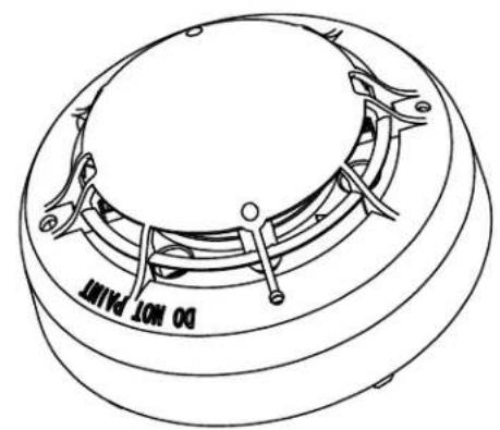
text_image
DO NOT PAINT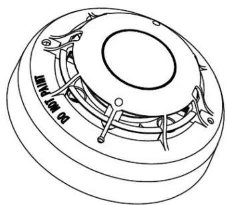
text_image
Juring 100 mm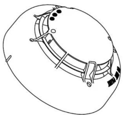
natural_image
Line drawing of a helmet with decorative bandages and dots (no text or symbols)Introduction
These instructions apply to all sensors listed on this Technical Bulletin for maintaining, clearing and testing. Failure to following these instructions may result in the failure of the sensors to initiate an alarm condition. Hochiki America Corporation is not responsible for sensors that have been improperly maintained, cleaned or tested.
Features
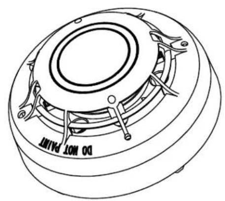
• ALN-V photoelectric smoke chamber detects smoldering/fast-flaming fires
• ATJ-EA combination fixed-rate of rise heat sensing element detects both fixed-rate of rise temperature
- ACC-V multi-criteria photoelectric smoke chamber and heat sensing element detects smoldering or fast-flaming fires and fixed temperature
- ACD-V multi-criteria photoelectric smoke chamber, combination fixed/rate of rise heat sensing element, and carbon monoxide (CO) detects smoldering/fast-flaming fires, fixed/rate of rise temperatures, and poisonous carbon monoxide (CO) gas.
- The combination of a high signal-to-noise ratio and sensitivity stability make this sensor effective in a wide range of environmental conditions
• User programmable alarm thresholds
• A reliable and fully digital transmission method, which is highly immune to noise
- The control panel is able to verify the status of any device. Whether the device is dirty or approaching an alarm condition, it can make this determination routinely
• It is possible to assign a priority to any device that is deemed necessary by the nature of the systems design
• There is an interrupt sequence, which can assign priority to fire and other similar signals
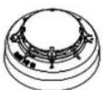
ALN-V
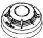
ATJ-EA
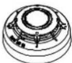
ACC-V
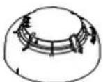
ACD-V
SENSOR SPECIFICATIONS
| CATEGORY | SMOKE SINORS | HEAT SINIOR | MULTI-CRITERIA SINORS | |
| Model | ALN-V | AT/JEA | ACC-V | ACC-V |
| Operating Voltage Range (Vdc) | 17 - 39.5 VDC | 24 - 41.0 VDC | 17 - 39.5 VDC | 24 - 41.0 VDC |
Placement of sensors
This section explains how to determine the number of sensors are needed, and where to place them. By following the guidelines listed in the NFPA 72, base the number and location of sensors on an engineering survey of the area to be protected.
Factors to consider:
- Contents to be protected
• Type of construction and use of structure
• Human occupancy
• Burning characteristics of contents
• Space involved
• Height of ceiling
• Surface condition of ceiling
• Total area
• Air movement (stratification)
• Vent location (velocities and dilution
• Deflections and obstructions
Sensor Location:
• One smoke sensor covers 450 to 900 square feet
• One heat sensor covers up to 2500 square feet
- Consider local conditions and codes along with engineering evaluations to determine the proper spacing and specification
WARNING: Heat sensors are not life safety devices. Smoke sensors are recommended where life safety is a factor
Examples:
- You may use 30' spacing on smooth ceilings for smoke sensors
- You may use 70' spacing on smooth ceilings for heat sensors
- Beams or other obstructions extending more than 18" below the ceiling reduce the effective range of the sensors. Such
- Beams or other obstructions extending more than 8" but less than 18" require reduced spacing at the perpendicular of the obstructions.
NOTE: For information on differing styles of construction consult the NFPA handbook, section 72.
WARNING: Do not install Hochiki smoke sensors in the following areas:
• Where temperatures are likely to exceed 100°F or fall below 32°F
• Closer than 4" to any side wall
■ Where forced ventilation can dilute the smoke from a fire
• In known areas of combustion such as kitchens or furnace rooms
text_image
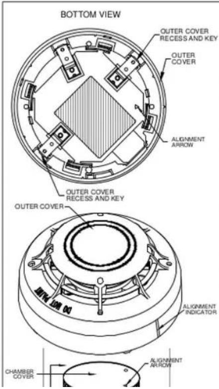
BOTTOM VIEW OUTER COVER RECESS AND KEY OUTER COVER ALIGNMENT ARROW OUTER COVER RECESS AND KEY OUTER COVER ALIGNMENT INDICATOR CHAMBER COVER ALIGNMENT ARROWManual Cleaning Procedures
This section explains how to clean the ALN-V, ACC-V, and ACD-V sensors.
Tools needed:
• Hochiki America's cover removal tool (CRT)
• Small soft bristled paint brush
• Denatured alcohol
• Compressed air duster
NOTE: Use only lint-free materials when clearing the chambers of the photoelectric smoke sensor. Use of fibrous materials may result in nuisance alarm.
Remove & Disassemble the Sensor:
- Remove the sensor from its attached base
- Disassemble sensor by following the CRT procedures found on page 4 of this Technical Bulletin
Clean the Sensor:
CAUTION: Do not remove the insect screen from the chamber cover
1. Remove the outer cover of the sensor as specified on page 4
2. Place the sensor in the palm of your left hand and grasp the chamber cover with your right hand. Twist the chamber cover counterclockwise until the Cover Tabs clear the Tab lock. Lift and separate the chamber cover from the optical unit
3. Swab the optical unit with denatured alcohol using a small soft bristled paint brush
4. Clean the chamber cover and the outer cover in the same manner
Clean the Sensor:
-
Locate the alignment arrows on both the chamber cover and the optical unit
-
Set the chamber cover onto the optical unit while making sure that alignment arrows are aligned with one another
- Press until the cover snaps into place
- Match the alignment indicator with the alignment arrow on the back of the sensor
- With the alignment indicator aligned with the alignment arrow, press firmly on the back of the sensor. The sensor will snap into the outer cover. The sensor is now ready to be returned to the base from which it was removed
- The sensor should be re-tested by following the test procedure
Cover Removal Procedures
This section explains how to remove the outer cover from the ALN-V, ATJ-EA, ACC-V, and ACD-V sensors by using the cover removal tool (CRT).
Tools needed:
• Hochiki America's cover removal tool (CRT)
Remove & Disassemble the Sensor:
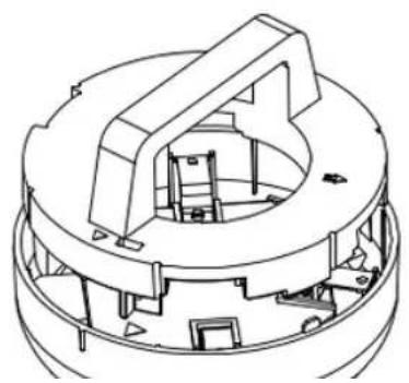
- Place the sensor to be disassembled on the CRT as shown
- Push the CRT. The sensor will automatically pop open
- The contact blades on the sensor will engage on the CRT
- Grasp the sensor firmly and rotate the CRT counter-clockwise (approximately 10^ )
- After the cover have been removed, refer to the sensor cleaning procedures to clean and reassemble the sensor
natural_image
Technical line drawing of a mechanical component with internal cavities and mounting holes (no text or symbols)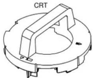
natural_image
Technical line drawing of a mechanical component with labeled 'CRT' (no other text or symbols)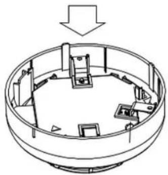
natural_image
Isometric line drawing of a circular mechanical or architectural component with internal compartments and structural elements (no text or symbols)
Testfire 1000 or 2000 with TS3 or TC3:
- Insert the battery baton, hold the Testfire head unit by the handle and depress the upper spring button on the battery baton. Align the button with the location hole in the handle and push the battery baton into the handle until the button springs up through the location hole.
- Insert the other end of the battery baton into the Solo access pole and depress the lower spring button. Align it with the location hole and push the battery baton further into the pole until the button springs up through the hole.
- Remove the capsule from its outer carton and Anti-Static bag.
- Remove the spring clip protector cap from the new capsule.
- Holding the capsule by spring clips with the label on the underside, carefully insert the new capsule into the capsule port. Push it into position, ensuring that the clips spring out positively on both sides of the capsule.
- Close the access cover securely.
- Program the tester to the following options available: Smoke, Heat or CO.
- Raise Testfire over the sensor. The sensor should touch the base of the inner dear cup.
- Lower Testfire from the sensor.
Testfire's LED Indications:
Blue Solid: Smoke test in progress
Red Solid: Heat test in progress
Green Solid; CO test in prog Green Slu Flushing; Starchy crude
Green Slow Flashing; Green Fast Flashing;
Red Flashing:
Smoke test in progress
Heat test in progress
CO test in progress
Standby mode
Operational mode
Battery needs charging, but still operational.
Burs still operational
Timeout indication (after 2 minutes)
2 minutes of continuous testing on one stimulus or
combination of stimuli
Error
00 coding
OO cooling phase wait
until standby mode status
before continuing to test CO
Alternating Red/Green Flashing
Red Solid
Green Solid
Alternating Red/Green
The Hochiki ACD-V is a Multi-Criteria Sensor. The ACD-V is capable of Smoke, Heat and CO Detection individually along with many criteria combinations based upon the activation mode setting of the detector (the activation mode is set through panel programming). To perform the detector test(s), the sensor must first be placed in an individual Activation Mode
text_image
Sample 500-Neuclid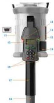
text_image
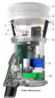
Labeled diagram of a medical or laboratory instrument with numbered parts from 1 to 18- Inner Clear Gap
- Platform
- Clear Cig
- Belltown
- NED Ave
- Induced Loss
- Main Dust for Heat, Smoke and CO ^®
- Tessire 100 RFID Bluetooth ^® Module ^***
- Smoke Capsule TSS
- CO Capsule T/C7*
- Lobe Port (on rear of unit)
- Lower Joveshoe Drake, E.C
- 'Test Type' USD
- "Status" LFD
- Smoke Capsule Access Cover
- CO Capsule Access Cover*
- Adjustable Handle
-
Battery Baron 9. Inflated Res
-
The brand's remote control has been
* Depending an rental qualification. **Future option.
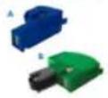
Replacement Capsules
A Testfire Smoke Capsule T53
8 Testfire CO Capsule TC3 ^®
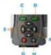
User Interface Keypad
C Metu Key
D Status Key
E. Matsu Navigation Key
F Erwin Kay
GONCH Key H. Evese Kim
B escape key
Programmer Operating Procedure
This section explains how to program the sensor's address using the TCH-B100 and TCH-B255 hand held programmer. The hand held programmer is designed for use with Hochiki's DCP protocol supported SLC devices.
Features:
• TCH-B100/-B255 is a compact design and easy to use
• Provides address setting and reading
• Diagnostic ability by displaying the analog value in real-time
• Uses 9VDC battery
• Automatically increments to the next address for addressing multiple
sensors
• Automatically switches the power to off after use
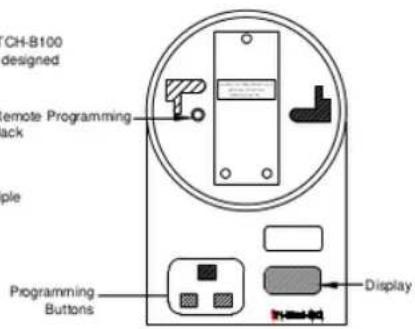
Programming Buttons:
Left Gray Button: Power on. Automatically reads the address of a sensor. Subsequent operations will advance the device address by ten.
Right Gray Button: Power off. Advances the device address by one. Stores the displayed address to the device and is used to read the sensor's analog values.
text_image
CH-B100 designed Remote Programming lock Programming Buttons DisplayAddress Setting:
- Install sensor onto programmer, ensuring that the sensor protrusion aligns with the programmer grooves
- Press the left gray button to switch programmer to on. A battery check message will appear followed by the device address (un-programmed sensors will read a default address of 127 or 255)
- Set the required address by incrementing the left and right gray buttons (the display will show three red flashing dots if the address being programmed is different from the device's current address)
- When the desired address is present, press the red button to store the address. The three red dots on the display will no longer be present
Reading Analog Value:
- Install the sensor and power up programmer as previously described
- Press the red button. An "A" will appear on the display followed by the analog value. This value will be continuously updated for three minutes or until the unit is turned off
- The "ALG" photoelectric sensor should display a value between 56-63
Display Message:
bAt: On power up (check battery).3000 address can be set in low

text_image
Remote Programming Cable (All Modules except DCP-FRCME-M and FRCME-P/FFO-MMP) To Remote Programming Jack or Remote Programming Cable (DCP-FRCME-P/FFO-MMP) RemoteProgrammer Operating Procedure
This section explains how to program the sensor's address using the TCH-B100 and TCH-B255 hand held programmer. The hand held programmer is designed for use with Hochiki's DCP protocol supported SLC devices.
Features:
• TCH-B100/-B255 is a compact design and easy to use
• Provides address setting and reading
• Diagnostic ability by displaying the analog value in real-time
• Uses 9VDC battery
• Automatically increments to the next address for addressing multiple
sensors
• Automatically switches the power to off after use
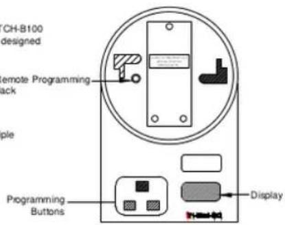
Programming Buttons:
Left Gray Button: Power on. Automatically reads the address of a sensor. Subsequent operations will advance the device address by ten.
Right Gray Button: Power off. Advances the device address by one. Stores the displayed address to the device and is used to read the sensor's analog values.
text_image
CH-B100 designed Remote Programming lock Simple Programming Buttons DisplayAddress Setting:
- Install sensor onto programmer, ensuring that the sensor protrusion aligns with the programmer grooves
- Press the left gray button to switch programmer to on. A battery check message will appear followed by the device address (un-programmed sensors will read a default address of 127 or 255)
- Set the required address by incrementing the left and right gray buttons (the display will show three red flashing dots if the address being programmed is different from the device's current address)
- When the desired address is present, press the red button to store the address. The three red dots on the display will no longer be present
Reading Analog Value:
- Install the sensor and power up programmer as previously described
- Press the red button. An "A" will appear on the display followed by the analog value. This value will be continuously updated for three minutes or until the unit is turned off
- The "ALG" photoelectric sensor should display a value between 56-63
Display Message:
bAt: On power up (check battery).3000 address can be set in low
