SOC-24V - Rauchmelder Hochiki - Kostenlose Bedienungsanleitung
Finden Sie kostenlos die Bedienungsanleitung des Geräts SOC-24V Hochiki als PDF.


Benutzerfragen zu SOC-24V Hochiki
0 Frage zu diesem Gerät. Beantworten Sie die, die Sie kennen, oder stellen Sie Ihre eigene.
Eine neue Frage zu diesem Gerät stellen
Laden Sie die Anleitung für Ihr Rauchmelder kostenlos im PDF-Format! Finden Sie Ihr Handbuch SOC-24V - Hochiki und nehmen Sie Ihr elektronisches Gerät wieder in die Hand. Auf dieser Seite sind alle Dokumente veröffentlicht, die für die Verwendung Ihres Geräts notwendig sind. SOC-24V von der Marke Hochiki.
BEDIENUNGSANLEITUNG SOC-24V Hochiki
INSTALLATION INSTRUCTIONS
These instructions apply to all Hochiki America detector bases that utilize an NS detector with LEDs to indicate power, and alarm.
CAUTION
Install the bases in this instruction in accordance with applicable NFPA standards, local codes, and the authorities having jurisdiction. Failure to follow these instructions may result in failure of the detector to initiate an alarm condition. Hochiki America is not responsible for detectors that have been improperly installed, tested, or maintained.
For testing and cleaning information, refer to Page 2 of these instructions and to Technical Bulletin HA-97 Conventional. Also refer to NFPA-72 Chapters 2 and 7 for Automatic Fire Detector installation guidelines, testing, and maintenance.
Use "3M" Weatherban # 606 non-flammable scaling compound to seal field wiring conduit openings in the mounting back box. Compliance with this request may reduce the occurrence of the "STACK EFFECT".
FIG. 1
| BASE | BOX MOUNTING | ||
| 3" OCT | 4" OCT | 4" SQR | |
| NS4-BASE | YES | NO | NO |
| NS6 BASE | NO | YES | YES |
| HSC-BASE | NO | YES | YES |
Connect wiring to the bases as shown in the wiring diagrams that follow. Detectors and bases may be mixed on the same initiating loop as long as the number of two-wire powered detectors does not exceed the specifications of the control panel (see Figure 2 below)
CAUTION
CONNECT WIRING TO TERMINALS AS SHOWN DO NOT LOOP WIRE UNDER TERMINALS. BREAK WIRE RUN TO PROVIDE SUPERVISION OF CONNECTIONS.
FIG. 2
| SPECIFICATIONS | SMOKE DETECTOR DATA | ||||||
| DETECTORS | SJJ-24/-24C SLR | LR-24/-24C/-24V/-24VC-24VN/-24H/-24HC | SLV-24V/-24N-24NW/SLV-24 | DCD-135/-135W/-135C-190/-190W/-190C-835C | SLR-835/-835W/- | SLR-835H/-835IW | SOC-24V/-24VNSOC-24VW |
| TYPE OF DETECTOR | IONIZATION | PHOTOELECTRIC | PHOTOELECTRIC | FIXED TEMP/RATE-OF RISE IHEAT | PHOTOELECTRIC | PHOTOELECTRIC | PHOTOELECTRIC |
| WORKING VOLTAGE (2-WIRE) | 15-33.0 VDC | 15-33.0 VDC | 15-33.0 VDC | 15.0-33.0VDC | 8.0~35.0 VDC | 8.0~35.0 VDC | 8.0~35.0 VDC |
| RATED VOLTAGE (4-WIRE) | 17.7-30.0 VDC | 17.7-30.0 VDC | 17.7-30.0 VDC | 17.7-30.0VDC | 8.0~35.0 VDC | 8.0~35.0 VDC | 8.0~35.0 VDC |
| VOLTAGE WAVEFORM | FILTERED DC*5V RIPPLE MAX. | FILTERED DC *5V RIPPLE MAX. | FILTERED DC *5V RIPPLE MAX. | FILTERED DC *5V RIPPLE MAX. | *15% RIPPLE MAX. | *FILTERERIDDC *15% RIPPLE MAX. | FILTERED DC *15% RIPPLE MAX. |
| MAX. ALARM CURRENT | 150 mA | 150 mA | 150 mA | 150 mA | 150 mA | 150 mA | 150 mA |
| MAX. SURGE CURRENT | 200μA | 160 Aμ | 160μA | 160μA | 200μA | 200μA | 160μA |
| AVERAGE STANDBY CURRENT | 40μA | 45 μA | 45μA | 35μA | 38μA @ 12 VDC55μA @ 24VDC70μA @ 35VDC | 38μA @ 12 VDC55μA @ 24VDC70μA @ 35VDC | 59μA |
| HEAT ELEMENT RATING | N/A | 135°F(SLR-24H only) | N/A | 135/190°F | N/A | 135°F | N/A |
| COMPATIBILITY IDENTIFIER | HD3 | IID3 | IID3 | IID3 | IID5 | IID5 | IID3 |
| SENSITIVITY TEST DEVICES | NSTT-A100 | BUILT-INTEST FEATURE | BUILT-INTEST FEATURE | TTA-1H | BUILT-INTEST FEATURE | BUILT-INTEST FEATURE | BUILT-INTEST FEATURE |
| HCP-1008E CONTROL PANEL | 30' ZONE | 30' ZONE | 30' ZONE | 30' ZONE 30' ZONE | 30' ZONE | 30' ZONE | |
Note: The SLR-24V, SLV-24V and SOC-24V are suitable for installation in air velocities up to 4000ft./min.
NOTE:
When mounting detector on a wall, it must be between 4" and 12" from the ceiling.
* When using a four-wir base full wave rectified AC can be used.
BASE STYLES
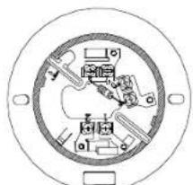
natural_image
Circular diagram with internal components and directional arrows, no visible text or symbolsNS6 SERIES (EXCEPT NS6-100)
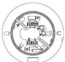
natural_image
Circular diagram with internal components and directional arrows, no visible text or symbolsNS6-100
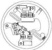
natural_image
Pure electrical circuit lines without any symbolsNS4 SERIES (4 INCH BASE) (EXCEPT NS4-100)
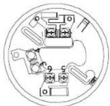
natural_image
Pure electrical circuit lines without any symbolsNS4-100
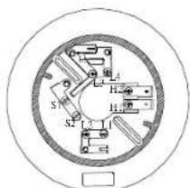
text_image
S S2 H1 H2 I I1HSC SERIES
(4 INCH BASE)
DSC-EA HEAT DETECTORS
| SPECIFICATIONS | HEAT DETECTOR DATA |
| DETECTOR MODEL | DSC-EA/DSC-EAW |
| DETECTOR TYPE | RATE OF RISE |
| TEMPERATURE RATING | 15°F/MIN. |
| MAX. ALARM CURRENT 100 mA | |
| UL LISTED TEMPERATURE | 0°C ~ 37.8°C(32°F - 100°F) |
| OPERATING TEMPERATURE | -10°C ~ 50°C(14°F - 122°F) |
DFE HEAT DETECTORS
| SPECIFICATIONS | HEAT DETECTOR DATA | |
| DETECTOR MODEL | DFE-135/-135W/DFE-135C | DFE-190/-190W/DFE-190C |
| DETECTOR TYPE | FIXED TEMPERATURE | FIXED TEMPERATURE |
| TEMPERATURE RATING | 135°F. | 190°F. |
| MAX. ALARM CURRENT | 100 mA | 100 mA |
| BASE:MODEL | ALARM CURRENT | COMPATIBILITY IDENTIFIER | LATCHING INDICATION |
| HSC-224L/-224LW | 35~42 mA @ 24V(54 mA MAX.) | HB-62 | YES |
| HSC-220L/-220LW | 67~80 mA @ 24V(88.5mA @ 26.5VDC MAX) | HB-64 | YES |
| HSC-221L/-221LW | 37~45 mA @ 24V(57mA MAX) | HB-63 | YES |
| NS4-100,100W | NON-CURRENT LIMITED | N/A | NO |
| NS6-100,100W | NON-CURRENT LIMITED | N/A | NO |
NOTE: BASES/ DETECTORS WITH THE "W" SUFFIX ARE WHITE IN COLOR. NOTE: BASES/ DETECTORS WITH THE "C" SUFFIX ARE CANADIAN.
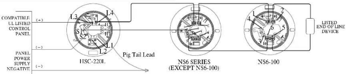
text_image
COMPATIBLE UL LISTED CONTROL PANEL (+) - (−) PANEL POWER SUPPLY NEGATIVE (−) L3 L4 S1 S2 L1 L2 HSC-2201. Pig Tail Lead NS6 SERIES (EXCEPT NS6-100) NS6-100 LISTED END OF LINE DEVICE| BASE | ALARM CURRENT | ID |
| NS6-224, 224W, 224C | 43mA (70mA @ 33.0V MAX.) | HB-5 |
| NS6-220, 220W, 220C | 93mA (136mA @ 33.0V MAX.) | HB-3 |
| NS6-221, 221W, 221C | 46mA (77mA @ 33.0V MAX.) | HB-4 |
| *NS6-100, 100W, 100C | 150mA @ 15.0~33.0V MAX. | HB-55 |
| NS4-224, 224W, 224C | 43mA (70mA @ 33.0V MAX.) | HB-5 |
| NS4-220, 220W, 220C | 93mA (136mA @ 33.0V MAX.) | HB-3 |
| NS4-221, 221W, 221C | 46mA (77mA @ 33.0V MAX.) | HB-4 |
| *NS4-100, 100W, 100C | 150mA @ 15.0~33.0V MAX. | HB-55 |
| IISC-224R/ 224RW/ 224RC/ RA/ RST 1 | 43mA (58mA @ 30.0V MAX.) | HB-73 |
| HSC-220R/ 220RW/ 220RC 1 | 88mA (98mA @ 26.5V MAX.) | HB-72 |
| IISC-221R/ 221RW/ 221RC 1 | 49mA (62mA @ 30.0V MAX.) | HB-71 |
| HSC-4R/ -4RC 2 | 43mA (58mA @ 30.0V MAX.) | N/A |
| HSC 4R12 | 47mA (75mA @ 18.0V MAX.) | N/A |
* - Requires External Current Limiting To 150mA Max.
① 2-WIRE AUXILIARY RELAY BASE
② 4-WIRE 24V BASE
2-WIRE OPERATION
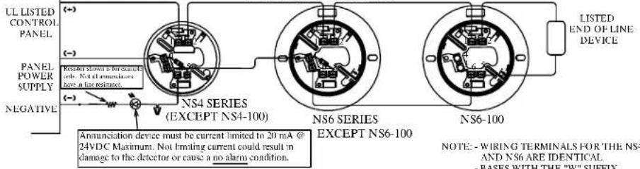
text_image
UL LISTED CONTROL PANEL POWER SUPPLY NEGATIVE (-) (-) (-) RSI#drol shown is for standard sds. Not all enciruses have in far resistance. NS4 SERIES (EXCEPT NS4-100) NS6 SERIES EXCEPT NS6-100 NS6-100 LISTED END OF LINE DEVICE Annunciation device must be current limited to 20 mA @ 24VDC Maximum. Not limiting current could result in damage to the detector or cause a no alarm condition. NOTE: - WIRING TERMINALS FOR 'THE NS4 AND NS6 ARE IDENTICAL. - BASES WITH THE "W" SUFFIX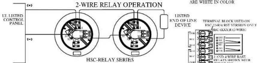
text_image
UL LISTED CONTROL PANEL (++) () 2-WIRE RELAY OPERATION HSC-RELAY SERIES LISTED END OF LINE DEVICE ARE WHITE IN COLOR TERMINAL BLOCK USED ON HSC 23A/RST VERSION ONLY HSC-1XXXR (2-WIRE) D08 6 NCL 5 N01 4 N01 3 N01 2 C08 1 2 AND 4 WIRE BASE RELAYS SHOWN WITH POWER OFF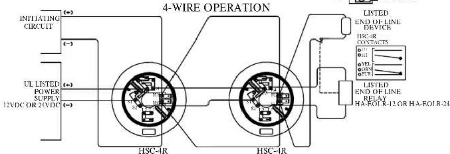
flowchart
graph TD
    A["INITIATING CIRCUIT"] -->|(*)| B["HSC-4R"]
    C["UL LISTED POWER SUPPLY 12VDC OR 24VDC"] -->|(*)| B
    B --> D["HSC-1R"]
    E["LISTED END OF LINE DEVICE"] --> F["HSC-4R CONTACTS"]
    F --> G["LISTED END OF LINE RELAY HA-FOLR-12 OR HA-FOLR-24"]
    G --> H["Output"]
    style A fill:#f9f,stroke:#333
    style C fill:#f9f,stroke:#333
    style E fill:#f9f,stroke:#333
SIJ-24/-24C SENSITIVITY TEST PROCEDURE
TEST DEVICE:
Testing is performed with the Hochiki America Alarm Test Magnet (Part Number 0700-01110) shown below.


TEST PROCEDURE
1). With detector wired to appropriate initiating circuit or current limited power source and with normal applied power, place magnet as shown in Figure 1.
2). Wait at least six seconds. Detector SHOULD not alarm and LED should not light.
3). Place magnet on detector as shown in Figure 2 (opposite side).
4). Wait at least six seconds. Detector SHOULD alarm
5). If detector does alarm when magnet is positioned as in Figure 1 or does not produce an alarm when magnet is positioned as in Figure 2, detector is not within specified sensitivity limits and may require service. See Tech Bulletin HA-97 for more information and for additional sensitivity test devices.
NOTE:
CONDUCT TESTING ONLY UNDER NORMAL STANDBY CONDITIONS. ABNORMAL OR LOW POWER CONDITIONS MAY AFFECT SENSITIVITY. ALWAYS RESET POWER PRIOR TO TESTING OF NEXT UNIT.
TESTING THE SLR-835/SLR-24 AND THE SLV-24 SERIES INSTALLATION For go/no-go testing, a magnet will be required.
- Hold the magnet just UNDER the word "TEST" as shown on Diagram A.
- The detector should alarm within 10 seconds (If control panel is programmed for Fire Alarm Verification, it may take up to 30 seconds).
- The detector's LEDs should be on Red continuously and any control panel indicating appliances should activate.
- Silence the system and activate the control panel reset to reset smoke detector.
- The smoke detector LEDs should flash Green.
TESTING THE SOC-24V/-24VN/-24VW
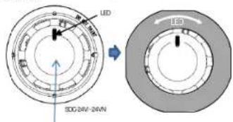
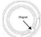
For go/ no-go testing, original test tool will be required.
- Hold the test tool on the detector like Diagram B.
- The detector should alarm within 10 seconds (If control panel is programmed for Fire Alarm Verification, it may take up to 30 seconds).
- The detector's LED should be on Red continuously and control panel indicating appliances should activate.
- Silence the system and activate the control panel reset to reset smoke detector.
- The smoke detector LED should flash Green.
SLR -24/-835/ SLV-24 AND SOC-24V SERIES SENSITIVITY TEST FEATURE
NOTE: The SLR-24/-24C/-24V/-24VC/-24VN/-24H/-24HC/-835/-835W/-835C/-835H/-835HW, SLV-24/-24V/-24N/-24NW and SOC-24V/-24VN/-24VW have a built-in automatic sensitivity test feature.
1) In normal condition both LEDs flash Green.
2) When the sensitivity drifts outside of its sensitivity limits, both LEDs flash Red
3) In the alarm state both LEDs are on Red continuously.
4) When the condition exists as stated in 2) the device needs to be cleaned or returned to the factory for servicing. Refer to Technical Bulletin IIA-97 for cleaning information.
NOTE: In case of SOC-24V/-24VN/-24VW, only 1 LED
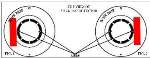
text_image
TOP VIEW OF 51-24V-24C DETECTOR FIG. 1 LED LED LED FIG. 2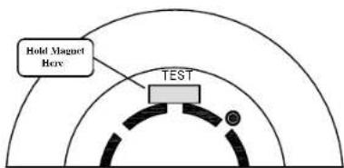
text_image
Hold Magnet Box TESTDIAGRAM A
text_image
UD SDG 24V-24VN 150°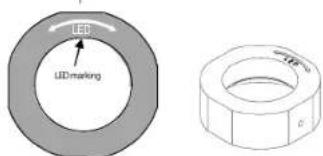
text_image
LED LED marking T10mm δTest tool
Test tool (back side)
DIAGRAM B
DWG. # HA-06-060
(Pg.2 of 2, 06/16)
PART# 1700-09987