
AR12NXWXCWKX - Klimaanlage SAMSUNG - Kostenlose Bedienungsanleitung
Finden Sie kostenlos die Bedienungsanleitung des Geräts AR12NXWXCWKX SAMSUNG als PDF.


Benutzerfragen zu AR12NXWXCWKX SAMSUNG
0 Frage zu diesem Gerät. Beantworten Sie die, die Sie kennen, oder stellen Sie Ihre eigene.
Eine neue Frage zu diesem Gerät stellen
Laden Sie die Anleitung für Ihr Klimaanlage kostenlos im PDF-Format! Finden Sie Ihr Handbuch AR12NXWXCWKX - SAMSUNG und nehmen Sie Ihr elektronisches Gerät wieder in die Hand. Auf dieser Seite sind alle Dokumente veröffentlicht, die für die Verwendung Ihres Geräts notwendig sind. AR12NXWXCWKX von der Marke SAMSUNG.
BEDIENUNGSANLEITUNG AR12NXWXCWKX SAMSUNG
Disassembling/Assembling the Cover Panel for Indoor Unit Installation
DB68-03934A-11


Please scan this QR code for detail video of indoor unit installation.
In order to install the indoor unit, you must disassemble the cover panel first. Please proceed following instructions to disassemble and assemble the cover panel. Hooks (on the cover panel) may get damaged if you apply excessive force as you disassemble and assemble the cover panel. Please follow the following instructions.
Removing the screws
Cover panel is assembled on the bottom part of the indoor unit (as shown in the illustration) and it is fastened with screws. Remove the Cap screw first and unfasten the screws so that you can disassemble the cover panel.
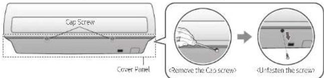
text_image
Cap Screw Cover Panel Remove the Cap screw Unfasten the screwRemoving the Cover panel (Before mounting the indoor unit)
The bottom panel fits the main body using the side, center, and bottom hooks as shown. Unlock the side hooks first, and then unlock the center and bottom hooks.
Check the location of the hooks before removing the cover panel.
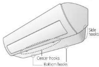
text_image
Side hooks Center hooks Bottom hooks▶ Location of the hooks on the central part
Number and location of the hooks
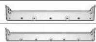
Center hook Bottom hook
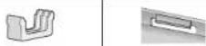
*For specific Hook location and quantity, please refer to cover panel with indicating arrows based on physical goods.
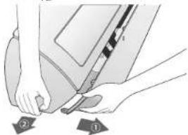
▶ Removing the hooks on the side × Caution (fragile)
- Gently press the both side of the cover panel inwards (①) and release the hooks on both sides(②)
natural_image
Illustration of hands using a tool to cut or mark a piece of items, with two labeled parts (① and ②) visible below the shapes.▶ Removing the hooks on the central part
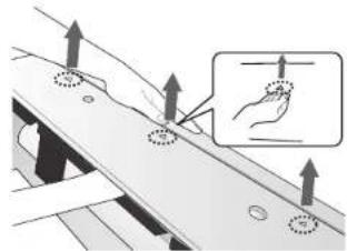
×Caution (fragile)
- Use both hands
- Release each hook by pushing it up at an angle.
natural_image
Diagram showing hand positioning on a mechanical component with circular features, no text or symbols presentAssembling the Cover panel (After mounting the indoor unit)
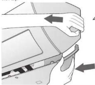
To assemble the Cover panel, proceed in reverse order of disassembling. Use both hands for assembling and be extra careful not to damage the pipes and drain hose. Lock the side, center, and bottom hooks in this sequence. Tighten the bottom panel with the screws, and close the screw holes with their cap.
natural_image
Illustration of hands holding a device with directional arrows indicating movement (no text or symbols)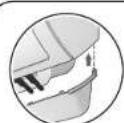
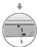
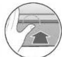
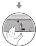
(Assemble the Cap screw)
* Please read instructions on the back of this manual for "Smart install mode". (Only for single system.)



Smart Install mode(Option) ※ For the multi system, this function is not supported.
- Check the installation status of the air conditioner.
1) Check the power supply, service valve (if it's open), power cable of the indoor and outdoor unit and amount of additional refrigerant required for pipe extension.
2) Status of the indicator after supplying the power: Standby status
- When the air conditioner is in standby status, use the remote controller to start the Smart Install mode.
1) Press the [Set/Cancel, Cancel or SET], [Mode], [Power] button simultaneously for 4 seconds.
▶ Smart Install mode can be operated only with the supplied remote controller
▶ During the Smart install mode procedure, remote controller cannot be operated.
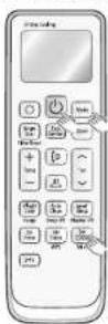
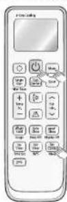
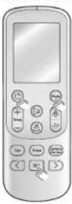
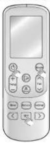
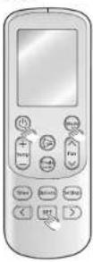
* Remote controller may be different (image/functions) depending on the model
2) Smart Install mode in progress
• 88 Display: Progress will be displayed in 0\~99.
• LED Display: Indicator on the indoor unit display will blink in sequence and then all indicators will
blink. (This will be repeated.)
| Type 88 Display LED Display Series | |||
| Indoor unit indicator | AR*****F***AR*****D***AR*****S***AR*****N*** | ||
| AR*****X*** | |||
* Display may be different depending on the model.
- Smart Install mode will end.
1) Smart Install mode will take approximately 7\~13 minutes. (Actual time may be different depending on the model.)
2) When Installation is successful: Smart Install mode will end with ringing sound and the air conditioner will be in standby status. (Error message will not be displayed on the indoor unit indicator and the remote controller and buttons on the indoor unit will work normally.)
3) When installation is not successful: Smart Install mode will end and error message will be displayed on the indoor unit display.

• Take necessary measures when error occurs.
- Refer to the service manual for necessary measures for each error that occurs.
- Use the product after taking care of the error that occurs.
| Error indicator | Error | Measures to take by an Installer | |||
| LED Display | |||||
| LED1 | LED 2 | LED 3 | |||
| / ≈ | |||||
| E 10 1 | ○ | ● | ● | Communication error between Indoor and outdoor unit | 1. Check the connection wire between indoor and outdoor unit (whether the power cable and communication cable is crossed or not) |
| E 12 1 | ○ | ● | ○ | Error on indoor temperature sensor | 1. Check the connection of the connector |
| E 122,E 123 | ● | ● | ○ | Error on indoor heat exchanger | 1. Check the connection of the connector |
| E 154 | ○ | ○ | ● | Error on indoor fan motor | 1. Check the connection of the connector2. Remove foreign substance (Check for the cause that restains motor) |
| 88 display and all LED blinksE 162,E 163 | ● | ● | ● | EEPROM/Option error | 1. Re set options |
| E422 | ● | ○ | ● | Refrigerant flow blocking error | 1. Check if the service valve is completely open.2. Check if there's any blockage in the refrigerant pipe which connects indoor and outdoor unit.3. Check for refrigerant leak. |
| E554 | ● | ○ | ● | Lack of Refrigerant (For Inverter model only) | 1. Check if sufficient amount of additional refrigerant was charged for the pipe length that exceeds 7.5 m.2. Check for refrigerant leak between valve and pipe connection. |
| ※ Above LED pattern is displayed when there's error is occurred on outdoor unit. Check the LED display on outdoor unit for the details. | |||||
* ○: Off / ●: Blinking / ●: On
