
23990 - Nicht kategorisiert Fisher & Paykel - Kostenlose Bedienungsanleitung
Finden Sie kostenlos die Bedienungsanleitung des Geräts 23990 Fisher & Paykel als PDF.


| Produkttyp | Kühlschrank-Umrandungsset (Surround Kit) |
| Marke | Fisher & Paykel |
| Modell | 23990 |
| Kompatible Kühlschrankbreite | 790 mm (31 1/8 Zoll) French-Door-Modell |
| Ausschnittmaße (B × T × H) | 962 × 700 × 1790 mm |
| Höhe mit 16-mm-MDF-Ausgleichsplatte | 1806 mm |
| Luftabzug (Tiefe) | 200 mm |
| Luftabzug (Breite) | 657 mm |
| Benötigte Werkzeuge | Elektrische Bohrmaschine, Kreuzschlitzschraubendreher, Bohrer Nr. 2 (lang) |
| Mitgelieferte Teile | 2–3 obere Montagewinkel, 10 seitliche Montagewinkel, 2 Bodenanschläge, untere Blende, Schrauben |
| Optional erforderlich | 16-mm-MDF-Platte (gleiche Größe wie Schrankboden), Joiner-Kit (Teilenr. 819264) für Side-by-Side |
| Installationsoptionen | Auf Bodenhöhe oder über Sockelleiste |
| Belüftung | Oben im Schrank erforderlich für effizienten Betrieb |
| Mindesttiefe des Schranks | 700 mm |
| Montagehinweis | Mit zwei Personen durchführen; Rollen und Füße müssen montiert sein |
Häufig gestellte Fragen - 23990 Fisher & Paykel
Benutzerfragen zu 23990 Fisher & Paykel
0 Frage zu diesem Gerät. Beantworten Sie die, die Sie kennen, oder stellen Sie Ihre eigene.
Eine neue Frage zu diesem Gerät stellen
Laden Sie die Anleitung für Ihr Nicht kategorisiert kostenlos im PDF-Format! Finden Sie Ihr Handbuch 23990 - Fisher & Paykel und nehmen Sie Ihr elektronisches Gerät wieder in die Hand. Auf dieser Seite sind alle Dokumente veröffentlicht, die für die Verwendung Ihres Geräts notwendig sind. 23990 von der Marke Fisher & Paykel.
BEDIENUNGSANLEITUNG 23990 Fisher & Paykel
Important!
SAVE THESE INSTRUCTIONS
The model shown in this document may not be available in all markets and are subject to change at any time. For current details about model and specification availability in your country, please go to our website www.fisherpaykel.com or contact your local Fisher & Paykel dealer.
① REFRIGERATOR SURROUND KIT
This kit is designed to be used with models with a cabinet height of between: 1695mm – 1806mm (66 34 ″ – 71 18 ″) with curved or flat door styling. You can find the part number for each installation type in Section 10.
To give the most integrated look, the kitchen cabinetry should be flush with the front of the refrigerator door.
Tools required (not included)
No. 2 drill bit – long
Electric drill
Phillips screwdriver
- 1 x 16mm ( 58 inch) piece of MDF the same size as the base of the cavity (optional). Not needed if refrigerator cabinet is sitting directly on the floor and not on raised toe kick area
- Joiner kit (part number 819264) required if joining two refrigerators side by side
Before starting
All dimensions are internal or cut out dimensions.
The refrigerator can be installed:
- In a cavity with a toe kick under the product with the bottom trim fitted to the base (diagram 1b/5).
- In a cavity with 16mm panel under the product with the bottom trim fitted to the panel (diagram 1a/6).
- In a cavity where the product is at floor level with no bottom trim (diagram 1a).
- Check whether your fridge has hinges concealed by the front of the fridge door. If unsure refer to page 2 note*** for instructions.
③ PARTS SUPPLIED
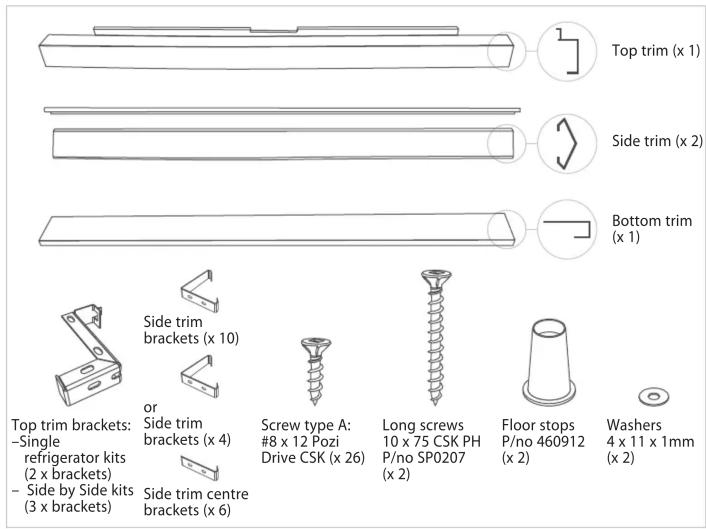
⑤ SECURE TOP
TRIM BRACKETS
Locate the two/three top trim brackets.
For the Side By Side Refrigerator kits, one bracket is to be screwed in the top centre of the cabinet, secure the top bracket with two of the screws (Type A, #8 x 12 Pozi Drive CSK).
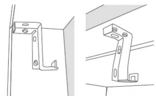
For all other kits, the two brackets are to be secured on either side, by two screws which are mounted from the side (see diagram 2).
Looking at the front of the product, place the top brackets on top of the wooden cabinet.
Care must be taken to line up the top front edge of the brackets with the leading edge of the cabinet.
Hint: Holes should be drilled in the centre of the slot in the brackets to allow for adjustment.
natural_image
Technical line drawing of two metal bracket components (no text or symbols)End bracket
Centre bracket
Diagram 2
⑥ SECURE SIDE
TRIM BRACKETS
Locate the ten side trim brackets.
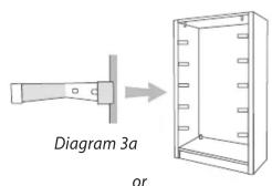
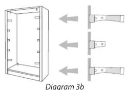
Position five brackets to the left hand side of the cabinet and the remaining five brackets to the right hand side of the cabinet.
Brackets should be evenly spaced down each side (see diagram 3a/b). Secure each of these brackets with the two screws provided.
Care must be taken to line up the front edge of the brackets with the leading edges of the cabinet.
② GETTING STARTED
1 Check that the internal Cupboard Cavity dimensions are correct (see diagram 1a/b).
2 Unpack the refrigerator and/or freezer cabinets from their separate delivery cartons (see individual cartons for unpacking procedures).
3 Ensure the floor and/or the cupboards are protected from damage during the unpacking and assembly of the cabinets.
4 Check the refrigerator and freezer doors are hinged on the desired side.
5 Check that the kit is complete (refer to Parts Supplied in section 3).
Note 1: Due to the size of the refrigerator cabinets, it is essential that assembly of the kit be undertaken with a minimum of two able-bodied persons.
Note 2: It is important to include adequate venting to the top of the cabinet to ensure the efficient operation of the refrigerator.
Note 3: The installation of the cabinet or cabinets can be at floor level as shown in diagram 1a or installed above the toe kick board as in diagram 1b.
Note 4: Rollers and feet must be fitted.
Note 5: Cabinets installed above the toe kit should have a floor base constructed to support the total weight of the loaded cabinet or cabinets placed on it.
The placement of the 16mm (5/8") MDF or plywood under the cabinet or cabinets on either installation type is to allow the fitment of the bottom trim that covers it. It is optional.
④ CABINETRY DIMENSIONS
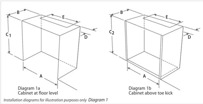
Cutout dimensions - flush to edge of door (mm / inches)
| 635 (25") model | 680 (26 1/4") model | 790 (31 1/8") model | 900 (35 7/16") model | 635 (25") model+ 635 (25") model | 680 (26 1/4") model+ 680 (26 1/4") model | 790 (31 1/8") model+ 790 (31 1/8") model | |
| A width | 807 (31 13/16") | 852 (33 9/16") | 962 (37 7/8") | 1072 (42 1/4") | 1467 (57 1/4") | 1557 (61 5/16") | 1777 (70") |
| B depth* | 700 (27 9/16") | 700 (27 9/16") | 700 (27 9/16") | 700 (27 9/16") | 700 (27 9/16") | 700 (27 9/16") | 700 (27 9/16") |
| C1 height** | 1790 (70 1/2") | 1790 (70 1/2") | 1790 (70 1/2") | 1875 (73 13/16") | 1790 (70 1/2") | 1790 (70 1/2") | 1790 (70 1/2") |
| C2 height*** | 1806 (71 1/8") | 1806 (71 1/8") | 1806 (71 1/8") | 1891 (74 1/2") | 1806 (71 1/8") | 1806 (71 1/8") | 1806 (71 1/8") |
| D air vent depth | 200 (8") | 200 (8") | 200 (8") | 200 (8") | 200 (8") | 200 (8") | 200 (8") |
| E air vent width | 502 (19 13/16") | 547 (21 9/16") | 657 (25 7/8") | 767 (30 1/4") | 1162 (45 3/4") | 1252 (49 5/16") | 1472 (58") |
* Depth is a minimum requirement
** Height is without 16mm MDF packer
*** Height is with 16mm MDF packer
Cut out dimensions above are to be used as minimum dimensions.
⑦ SECURE FLOOR STOPS
Two floor stops are supplied to prevent the refrigerator from being pushed too far back into the cavity. These are mounted on the base or floor at a distances of 688mm (27") from the face front edge of the trim kit.
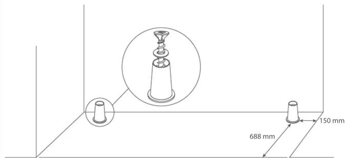
Diagram 4

TRIM INSTALLATION
The bottom trim is designed to cover the front edge of the floor base panel of the cabinet. This trim can be installed on a raised toe kick (diagram 1a) or toe kick below the refrigerator (diagram 1b)
16mm ( ^5/_8 inch) plywood or MDF board insert
Remembering that if this trim is to be used with the refrigerator at floor level the cut out dimensions will need to have 16mm (5/s") added to its height to allow for the bottom trim to be fitted. Note this trim is optional on this type of installation. If used with a raised toe kick the 16mm packer should be part of the base (diagram 5). Therefore 16mm is not required to be added to the height dimension.
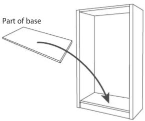
- If used place the 16mm (5/8") piece of plywood or with bottom trim fitted into the cavity (diagram 5 or 6). Note the piece should be the same size as the base of the cavity.
- Remove protective coating film from surround trim.
- To install the surrounds, first clip in the top surround. Ensure the locator strips at the rear of the top brackets clip into the rear of the top trim.
- Clip both side trims into place starting from the front cabinet edge.
Diagram 5

MOVE INTO CAVITY
If installing two refrigerators/freezers side by side a joiner kit is required. Refer to these instructions and fit joiner kit before pushing refrigerator into place, see diagram 6.
Plug refrigerator into electrical socket, run water connection to refrigerator if required (Ice & Water models only).
Gently install refrigerator into cabinetry making sure it is centred within the surround trim.
The front of the refrigerator door should be flush with the front of the cabinetry to obtain an integrated look.
Ensure the front leveling feet are adjusted to take the load of the fridge and keep it in place.
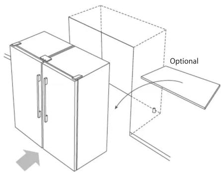
Diagram 6

KIT PART NUMBERS AND CUT OUT DIMENSIONS TABLE
| Refrigerator Model | Kit Part Numbers Cut Out Dimensions | ||||||
| Brushed Stainless | Plus Joiner Kit | Width A | Depth B* | Height C** | |||
| 1 x 635 (25") LH | 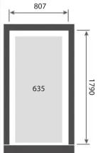 | 23980 80 | 7mm | 3113/_16" | 700mm 27^/_16" | 1790mm 70^1/2" | |
| 1 x 635 (25") RH | 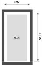 | 23981 80 | 7mm | 3113/_16" | 700mm 27^/_16" | 1790mm 70^1/2" | |
| 2 x 635 (25") | 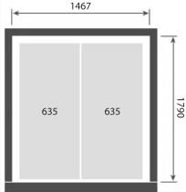 | 23982 81 | 9264 1467mm | 5734" | 700mm 27^/_16" | 1790mm 70^1/2" | |
| 1 x 680 ( 26^3/4 ") LH | 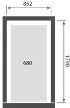 | 23983 85 | 2mm | 3316" | 700mm 27^/_16" | 1790mm 70^1/2" | |
| 1 x 680 ( 26^3/4 ") RH | 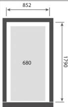 | 23984 85 | 2mm | 3316" | 700mm 27^/_16" | 1790mm 70^1/2" | |
| 2 x 680 ( 26^3/4 ") | 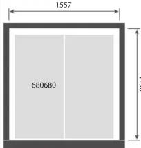 | 23985 81 | 9264 1557mm | 61316" | 700mm 27^/_16" | 1790mm 70^1/2" | |
| Refrigerator Model | Kit Part Numbers Cut Out Dimensions | ||||||
| Brushed Stainless | Plus Joiner Kit | Width A | Depth B* | Height C** | |||
| 1 x 790(31 1/8")LH | 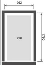 | 23986 96 | 2mm | 37^7/8" | 700mm 27^9/16" | 1790mm 70^1/2" | |
| 1 x 790(31 1/8")RH | 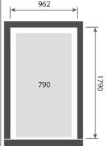 | 23987 96 | 2mm | 37^7/8" | 700mm 27^9/16" | 1790mm 70^1/2" | |
| 2 x 790(31 1/8") | 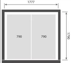 | 23988 81 | 9264 1777mm | 70" | 700mm 27^9/16" | 1790mm 70^1/2" | |
| 1 x 900(35 7/16")(French door model) | 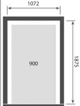 | 23989 10 | 72mm | 42^1/4" | 700mm 27^9/16" | 1875mm 73^13/16" | |
| 1 x 790(31 1/8")(French door model) | 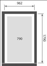 | 23990 96 | 2mm | 37^7/8" | 700mm 27^9/16" | 1790mm 70^1/2" | |
* Depth is a minimum requirement
** Height is without 16mm MDF packer
*** For refrigerators / freezers where the hinge is not concealed
by the door refer to spare parts for the correct kit number.
820413 D should list non concealed number kit.
Before you call for service or assistance ...
Check the things you can do yourself. Refer to the installation instructions, your User Guide – in particular the troubleshooting section and check that:
1 your product is correctly installed.
2 you are familiar with its normal operation.
If after checking these points you still need assistance or parts, use the link at www.fisherpaykel.com for regional service providers.

Marke : Fisher & Paykel
Modell : 23990
Kategorie : Nicht kategorisiert