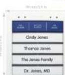
MX-Bell1-Button-F4 - Nicht kategorisiert Mobotix - Kostenlose Bedienungsanleitung
Finden Sie kostenlos die Bedienungsanleitung des Geräts MX-Bell1-Button-F4 Mobotix als PDF.


Benutzerfragen zu MX-Bell1-Button-F4 Mobotix
0 Frage zu diesem Gerät. Beantworten Sie die, die Sie kennen, oder stellen Sie Ihre eigene.
Eine neue Frage zu diesem Gerät stellen
Laden Sie die Anleitung für Ihr Nicht kategorisiert kostenlos im PDF-Format! Finden Sie Ihr Handbuch MX-Bell1-Button-F4 - Mobotix und nehmen Sie Ihr elektronisches Gerät wieder in die Hand. Auf dieser Seite sind alle Dokumente veröffentlicht, die für die Verwendung Ihres Geräts notwendig sind. MX-Bell1-Button-F4 von der Marke Mobotix.
BEDIENUNGSANLEITUNG MX-Bell1-Button-F4 Mobotix
text_image
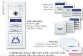
M6-Bell-Core available Bell Button bus accessory M6BODTX BullRFD M6-Bell-Core in IP Video Door Station Wipe frame white I/O BullRFD base module with 1 admin and 5 user IRFD cards RFID cards for keyless entry included 3 admin card, 5 user card • BullRFD base module with 1 admin and 5 user IRFD cards- BellRFD base module with 1 admin and 5 user RFD cards
- Interchangeable bell button sets (not included)
- Integrated RFD technology for keyless entry
- Available colors: white, silver, dark gray, black, orange
- Usable with/without function button for mailbox control
- Up to 60 hrs backup power supply using DoenMaster accessories
Bell Button Module with RFID Technology for up to Five Parties
Module for MCBOTIX IP Video Door Station, hayless entry and mailbox control, can be combined with the different bell button sets MX-Bell-Button-F1/F2/F3/F4/OS/XL1
Free-of-charge printing service on www.mobotic.com > Support

STB,PLV7.09/2013
Available Bell Button Sets (for all color variants)

NX-Bell1-Button-F1
Large bell button
with function button

MX-Said-Button-F2
inline-social button
with location button

MX-Shell-Burton-F3
Charge, 2 small load buttons
with fuse-down button

WK-Bell-Button-F4
4 mill bolt before
with landon button

MX-Baill-Burton-GD
3. Series I and Sufthoris
(No Junction Buffalo)

MX-Ball1-Bullon-XLI
XI-Ball Sutherland
Two Functionals Sutherland
You can use the blue function button of the door station to listen to new mailbox messages, record new announcements and activate/deactivate the mailbox. Visitors can leave a message even without the function button. The remaining mailbox features are easily controlled using the remote station of the door station (i.e., MOBOTIX App).
Each BellRFD base module contains 6 RFD cards (I admin, 5 user cards). Each button set contains pre-cut name plates made of UV-resistant paper. If required, you can replace the button sets later on – in the same base module. In order to configure the system using BellRFD, the bell buttons are replaced by a keypad insert, which is delivered with the base module.
Use our free-of-charge Printing Service on www.mobotix.com, Support section!
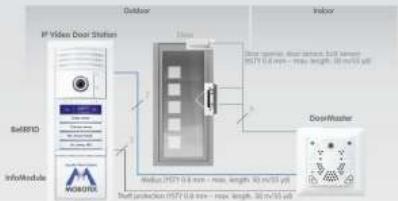
Standard Connection: IP Video Door Station with BellRFID, InfoModule and DoorMaster
flowchart
graph TD
    A["Outdoor"] --> B["Indoor"]
    B --> C["DoorMaster"]
    D["IP Video Door Shifter"] --> E["Info Module"]
    E --> F["Data: HST 0.6 mm - max, length: 42 m/53 μF"]
    F --> G["Start protection HST 0.6 mm - max, length: 42 m/53 μF"]
For additional information on the other connection reports and for installing, and the 204 System Manual Port Fair View Manitoba.com » Support » Manuals

UFO Serviziengalt
Sealing plug

The BelRFID module is installed in the exactly some manner as the KeypadRFID module. Makes sure that you follow the steps for the different hardware scenarios of the IP Video Door Station (with/without DoorMaster) as described in the T24 System Manual Part I for the KeypadRFID (see below).
Note: BellRFD and KeypadRFID can only be used on one MiBus with a later software version of the camera.
Installation and Initial Operation of the BellRFID
Before starting the installation and initial operation, you should download part 1 and 2 of the T24 System Manual from the NOBOTX website www.nobotix.com > Support > Manuals!
If the installation of the IP Video Door Station with BellRFD is not followed by the initial operation right away, MOBOTX recommends to remove the keypad insert and to insert the button set before starting the installation. This way, the soft rubber surface of the BellRFD base module is well protected until the module is brought into service (bell buttons are then replaced by the keypad insert). Note that the base module is weatherproof even without the bell buttons.
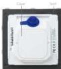
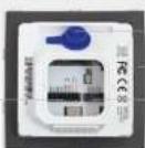
When replacing the button set or exchanging name plates, you need to remove the module from the frame of the IP Video Door Station. Use the blue MOBOTX key for unlocking the module. Make sure that you are activating the mechanical theft protection with the red turning knob in the door station frame only after you have finished the initial operation (see Section 4 Mechanical Anti-Thall Protection Locks in the T24 System Manual Part 1).
In order to avoid having to remove the module and install it again, you should insert the proper name plates before starting the initial operation. Use our free-of-charge printing service on www.asobotLix.com in the Support section! Or use the supplied name plates made from sturdy specialty paper and write the names using a UV-resistant marker
1. Insert the Name Plate(s)
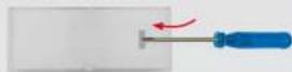
Remove the silicon insert from the button. Recommendation: Take a suitable tool without a sharp blade, cautiously insert it into the slot, gently press inward and lift the tool as shown.
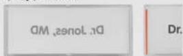
Insert the labeled or printed name plate as shown (the arrows at the side are pointing upwards later on).
Place the silicon insert on top of the name plate, push it into the frame at the top and at the bottom of the center, then push its sides into the frame.
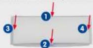
Make sure that the silicon insert fits flush into the frame of the bell button as shown to protect the name plate against humidity.

2. Insert the Module into the Door Station
You can use the BelRRD module as an alternative to the KeypadRFID (but not yet side-by-side) in the frame of an IP Video Door Station. For installing and wiring the module, follow the same steps as for the KeypadRFID.
Follow the description in the Section «Installing the T24-KeypadRFID» of the T24 System Manual Part 1. Likewise, the other connection variants listed in the Section «Overview: Connection and Wiring Diagrams» (e.g., connecting an electrical door opener in a system without DoorMaster).
Finish the installation of the BellRFID module by following the steps listed in the Section «Finishing the Installation» of the T24 System Manual Part 1. Similar to the KeypadRFID, the blue and the green status LEDs are flashing (power supply OK, ready for auto configuration).
Installation Hint
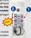
When installing the module, insert it first on the right-hand side. Then use two fingers and press on the left-hand edge until the module clicks into the frame. Caution: Only press at the edge, never at the center of the module! Make sure that the cabling is not pinched and damaged when installing the module.
3. Execute Auto Configuration
Place the supplied keypad insert into the base module (push it into the frame at the top, then push the bottom into the module).
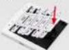

Start the auto configuration of the IP Video Door Station by executing the steps listed in the Section «Step 1: Performing the Auto Configuration» of the 724 System Manual Fort 2 (connect all devices, establish the power supply and press the bell button of the camera module immediately after the light and bell buttons are lighting up).

Once you have successfully completed the auto configuration, the white camera illumination is on and the BellRID shows the following status: • The blue and the green status LEDs are flashing.
- The LED of the keypad behind the top right key OK is red.
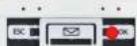
Finish the auto configuration by executing the steps listed in the Section «Functional Test Part 1» of the 124 System Manual Part 2.
4. Enter Super PIN and Confirm
The Super PIN is used to protect the system against misuse and also replaces the factory default password (TMLMAN) as the new admin password. The password is also used when adding the door station to the MOBOTIX App or MeEasy, for example: user name is adria, new password is the
Installation and Initial Operation of the BellRFID (contd.)
Enter your personal Super PIN on the keypad insert, then press the OK key. This key is now highlighted yellow.
Enter the Super PIN again, then confirm by pressing the OK key. If the two PINs are identical, the LEDs in the center are flashing repeatedly in a sequence from top to bottom. Next, the top right key OK lights up green and the key at the center (Letter) lights up red.
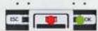
Remove the keypad insert and continue with the next step.
Niche
If you entered different Super PINs or more than 60 seconds passed between entering the PIN and confirming, the module emits a warning sound and returns to the state after finishing the auto-configuration. In such a case, you need to start again with step 4.
5. Set the Bell Button Set to be Installed
Depending on the bell button set, you need to select one of the six possible button layouts. To select a button layout, press any one of the button contacts in the center. The module shows the current button layout by flashing the LEDs in a specific manner (see table below). The configuration starts with pattern a, pressing any button switches to the next pattern in ascending order. After the last pattern, the module returns to pattern a

Pattern 1 (M00-Bull-Bydun-FY) (LO) 1 penetrally blue (Bucken) matherz (LO) 2 in 5 inches (white & dual) butterm
Press any one of these buttons
| Pattern | Button Set | Description |
| a | MAX-Buff-Buffon-F1 | LED 1 permanently blue, 2 to 5 floating white |
| b | MAX-Buff-Buffon-F2 | LED 1 permanently blue, 2+3, 4+5 sequence white |
| c | MAX-Buff-Buffon-F3 | LED 1 permanently blue, 2, 3, 4+5 sequence white |
| d | MAX-Buff-Buffon-F4 | LED 1 permanently blue, 2, 3, 4, 5 sequence white |
| e | MAX-Buff-Buffon-08 | LEDs 1, 2, 3, 4, 5 sequence white |
| f | MAX-Buff-Buffon-XL1 | LEDs 1 to 5 floating white simultaneously |
Once you have found the proper pattern, keep any one of the buttons at the center pressed until the LEDs are flashing repeatedly in a sequence. Next, the top center and right buttons OK and Letter light up green and the button at the top left (ESC) lights up red.
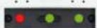
The button contacts are now locked until the function and bell buttons have been inserted and the admin card has been trained.
6. Insert the Function/Bell Buttons
In order to insert the function or bell buttons, you need to remove the BellRD module from the frame of the door station (if you have not already done so). Use the blue MOBOTX key for unlocking the module.

Insert the function and bell buttons in the proper order by inserting the elements from the bottom (e.g., the blue function button first), in order to avoid damaging the buttons, press the elements into the module using two thumbs as shown.
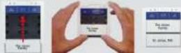
Click the BellFD module with the buttons into the IP Video Door Station as described in step 2.
7. Train the Admin Card
Now that you have entered the Super PIN and inserted the buttons, you need to train the Admin cord. This cord is used as the "master key" for authentication purposes and is required for training and deleting user cards, for example. For every-day use, however (opening doors, mailbox features), you only need the blue user cards. Note that you should always keep the admin cord together with the Product Pass of the IP Video Door Station in a safe place.
Hold the admin card in front of the BellFID module for 5 seconds until the sound stops. The LEDs light up in a sequence to confirm that the card has been trained.
All three LEDs of the top are now green to show that the initial operation has been completed successfully. The button contacts are now unlocked

Continue with step 8 or finish the installation as described in the T24 System Manual Part 2.
8. Add User Cards (Any Time Later on)
This step is not part of the initial operation of the system and can be performed at any time later on. You can skip this step if you do not intend to use the features described here.
The blue user cards are used by the inhabitants to open the door without using a key and to listen to mailbox messages directly at the IP Video Door Station. If the blue function button at the top has not been installed, make sure that you pay attention to the corresponding key position for the LED patterns described in the following.
Hold the trained admin cord in front of the BellRFID module. The OK/MENU key at the top right position lights up red.
If you want to use the keyless entry features and listen to mailbox messages of the door, press the bell button of the party to which you want to assign the user card. The selected button lights up white. If you want to use this card only for opening the door (i.e., for the nursing service) make sure that you do not press any button now.
Hold the user card in front of the BelRFD module for 5 seconds until the module plays a sound. The LEDs light up in a sequence to confirm that the card has been trained.
If you want to train additional cards, repeat the steps listed in this section for each card.
Test the trained cards by holding them in front of the BelRRD module one by one. The electrical door opener should open the door with each card.
In Case of Loss/Theft: Delete All Cards!
In case a user card is lost, you need to delete this card in order to prevent unauthorized access to the door. The easiest method is to delete all cards (user and admin) and to train the remaining cards again later on.
In order to delete all cards, hold the red admin card in front of the BELIRD module until the OK/MENU key lights up red. Then briefly remove the admin card and hold it in front of the module again (the ESC/ALARM key flashes red).
Now press and hold any bell button until the three LEDs at the top start flashing red. Confirm the deletion by again pressing and holding the same bell button. The LEDs light up in a sequence to confirm that all cords have been deleted. The right status LED of the module briefly lights up green.
If you want to train the cards again, execute the instructions of steps 7 and 8.
Note: It is also possible to delete only specific user cards or a lost admin cord. For additional information on how to do this, see the T24 System Manual Part 2.
Operation: Buttons and Signaling
Ring the Bell for One Party
Briefly press the bell button of the desired party. The LED of the button briefly lights up.
Leave a Message (BeRREID with Function Button)
• After pressing a bell button and announcement: Keep the blue letter key pressed while leaving the message.
- Without having pressed a bell button: Briefly press the blue letter key and then the bell button of the party for which you want to leave the message. As soon as the mailbox announcement stops, you can start talking. Keep the blue letter key pressed the entire time.
Leave a Message (BellRD without Function Button)
- After pressing a bell button and announcement: Keep the same bell button pressed while leaving the message.
- Without having pressed a bell button: Not possible
Open door with blue user cord
Hold the blue user card in front of the BellFID module. If the module denies access (e.g., card has been deleted, is not trained), the red status LED above the ESC/ALARM key lights up.
Upon Power Failure (Red LED Is Floching)
Press and hold the ESC/ALARM key until the button illumination lights up. You can now open the door with your user card during the next 10 seconds. This feature is only available if the IP Video Door Station is equipped with a DoorMaster.
Play Back New Message\*
If you are opening the door with a user cord and the blue letter key is flashing (5 seconds), there is at least one unflagged message in the corresponding mailbox. You can now use one of the following functions:
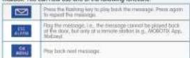
The mailbox closes automatically 15 seconds after the last user action/ message or if you press the ESC/ALARM button.
Notes
- Please follow the notes on installing and operating the device in the T24 System Manual(www.mobotix.com in the Support > Manuals section). This document contains the wiring diagrams for the different connection variants.
- The BellFID module is only to be used in the original frame of the MOBOTK IP Video Door Station.
- Before instilling, make sure that the seal on the back of the BellRD module has been properly attached.
- When inserting the module into the frame, only press at the edge, never at the center of the module.
- Make sure the device is not operated outside of its operating temperature range of -30 to +60^ / -22 to +140^ .
- BelRFID and KeypodRFID can only be used on one MiBus with a later software version of the camera.
Recording New Mailbox Messages\*
You can either use one of the system's predefined announcements or record custom announcements. These announcements will be played back if the mailbox is activated and the ringing has not been answered. A new custom announcement always replaces the last announcement that had been used. You can set the current announcement using a remote station (e.g., NOBOTK App, MxEosy).
Press your bell button and hold the blue user cord in front of the module (bell sound is played back, green LED mailbox activated or red LED mailbox deactivated lights up). Press the bell button again and keep it pressed as long as you record the announcement. The red status LED is flashing while recording.
Additional BellRFID Features (see T24 System Manual)
Activating/Deactivating the Malbox\*
Checking the Mailbox without Opening the Door\*
Keep the blue letter key pressed until it starts flashing, then hold the blue user cord in front of the module. The first new message is played back. Press the blue letter key to play back the messages again. To delete the messages, keep the ESC/ALARM pressed until you hear a sound. If there are no new messages (any more), the system will make a corresponding announcement.
Deleting User/Admin Cards and Transponders
- Cord held in front of the module
• All cards assigned to one bell bit
- Lost admin card
- Specific user card or transponder using the designed transponder number
Transponder
Chonging the Super PIN
Changing the Bell Button Set
Technical Specifications
| Interface Value | |
| Inputs | 2 galvanically separated inputs (AC/DC, self-powered, up to 50 V) |
| Outputs | 1 totaled daily output/AC/DC, up to 50 V/60 V/2.4 |
| Protection class (PAS DR IN 819378) | |
| Operating temperature -30 kV +60°C-23 kV +140°F (DR IN 50035) | |
| Power Supply (Wdc) | |
| Power consumption Type(1 F) | |
| RWD cards Type/Transcription WARE DERIVE EV 961005/4ES | |
LED Patterns
text_image
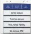
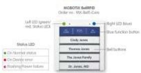
MOBOTX SallRFD Order no. NX-Ball-Data Left LED (green/red, Status LED) Right LED (blue) Blue function button Clady lanes Thermost lanes The James Family Dr. James, MD Bell buttons Status LED On Number status On Density error Reseting/Power issuesDimensions