Digistat +RF3 - Thermostat Drayton - Kostenlose Bedienungsanleitung
Finden Sie kostenlos die Bedienungsanleitung des Geräts Digistat +RF3 Drayton als PDF.


Benutzerfragen zu Digistat +RF3 Drayton
0 Frage zu diesem Gerät. Beantworten Sie die, die Sie kennen, oder stellen Sie Ihre eigene.
Eine neue Frage zu diesem Gerät stellen
Laden Sie die Anleitung für Ihr Thermostat kostenlos im PDF-Format! Finden Sie Ihr Handbuch Digistat +RF3 - Drayton und nehmen Sie Ihr elektronisches Gerät wieder in die Hand. Auf dieser Seite sind alle Dokumente veröffentlicht, die für die Verwendung Ihres Geräts notwendig sind. Digistat +RF3 von der Marke Drayton.
BEDIENUNGSANLEITUNG Digistat +RF3 Drayton
Drayton
Digistat+ & Digistat+RF
Room Thermostat
Models:
30002 / RF601

Inversys Controls Europe
Technical Helpline: -44 (0) 845 130 7722 www.drcsoncnotals.co.uk
Installation / User Guide 064S0056801 (09/05)

Cart II carbon Mark
Installation Guide
Technical Data
DIGISTAT+, DIGISTAT+RF
ROOM UNIT
Power Supply: 2 x AA Size, 1.5V alkaline batteries
Switch Type & Rating:
Relay version: SPDT 2(1)A 12-240V AC(DC) Volt free
Radio frequency:
RF version: 433 MHz
Radio Signal Range: 30m typically. The range may be affected by
(RF Version) the composition / density and number of
walls between the Digistat RF and SCR.
Temperature Range: 5 to 30°C
Control Accuracy: +0.5K @ 20°C
Ambient Temperature: Operating 1^ C to 50^ C /
Storage -20°C to 55°C
Applicable Standards: EN60730-1:2001; EN607302-7:1992
73/23/EEC Low Voltage Directive
89/335/EEC EMC Directive
EN300220-1
Mounting: Suitable for surface or conduit box
mounting
Wiring:
Relay: Designed for fixed wiring only, to comply
with current IEE regulations.
RF: No wiring required
SINGLE CHANNEL
RECEIVER (SCR)
230V AC 50Hz
Switch Type & Rating: 5FDT (voltage free) 2(1)A 230V AC or
23V AC (DC)
Wiring: Designed for fixed wiring only, to comply
with current IEF regulations
432 MHz
Reception Frequency:
Location
Room Thermostat
natural_image
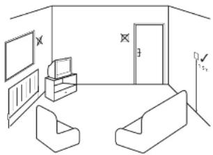
Line drawing of a room layout with furniture and wall-mounted screens (no text or symbols)Care should be taken to mount the thermostat in a position which is not subject to direct sunlight or draughts. Preferably it should be mounted on an inside wall about 1.5m (5ft) above the floor in a position where it can respond to room temperature but away from the direct influence of radiators or other appliances giving off heat. Before installation
2.2.1.1 陈晓明 王晓敏
If you do not have the knowledge to install the thermostat safely then you must arrange for a competent electrician to install it for you. Wiring must conform to the current IEE regulations.
Prior to commencing the installation you must ensure the mains
supply is switched off.
Remove battery
compartment
Loosen screw
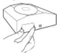
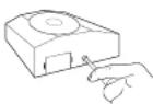
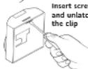
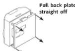
Standard cable entry is from the rear, but if surface wiring, from the top or bottom, is to be used, or extra space for cabling is required, use the optional Pattress box (sold separately).
WIRING
Room Thermostat (not RF models)

When changing an existing product and there is a neutral wire present, use the neutral (N) terminal on the product.
FAULT DIAGNOSIS (All Models)
If the display shows E1, the following faults could have occurred
-
Internal temperature sensor has failed
-
Ambient temperature is outside product operating temperature
range.

06193156001 155 E
Drayton
Digistat+ & Digistat+RF
Room Thermostat
Models:
30002 / RF601

Invensys Controls Europe
Technical Helpline: +44 (0) 845 130 7722
www.draytentrols.co.uk
Installation / User Guide 0649105600T (US705)

User Guide


What is a room thermostat?
... An explanation for householders
A room thermostat simply switches the heating system on and off as necessary. It works by sensing the air temperature, switching on the heating when the air temperature falls below the thermostat setting, and switching it off once this set temperature has been reached.
Turning a room thermostat to a higher setting will not make the room heat up any faster. How quickly the room heats up depends on the design of the heating system, for example, the size of boiler and radiators.
Neither does the setting affect how quickly the room cools down. Turning a room thermostat to a lower setting will result in the room being controlled at a lower temperature, and saves energy.
The heating system will not work if a time switch or programmer has switched it off.
The way to set and use your room thermostat is to find the lowest temperature setting that you are comfortable with, and then leave it alone to do its job. The best way to do this is to set the room thermostat to a low temperature – say 18°C – and then turn it up by one degree each day until you are comfortable with the temperature. You won't have to adjust the thermostat further. Any adjustment above this setting will waste energy and cost you more money.
If your heating system is a boiler with radiators, there will usually be only one room thermostat to control the whole house. But you can have different temperatures in individual rooms by installing thermostatic radiator valves (TRVs) on individual radiators. If you don't have TRVs, you should choose a temperature that is reasonable for the whole house. If you do have TRVs, you can choose a slightly higher setting to make sure that even the coldest room is comfortable, then prevent any overheating in other rooms by adjusting the TRVs.
Room thermostats need a free flow of air to sense the temperature, so they must not be covered by curtains or blocked by furniture. Nearby electric fires, televisions, wall or table lamps may prevent the thermostat from working property.
Your new thermostat with digital display.
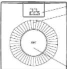
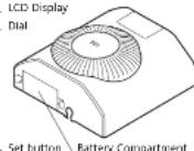
Thermostat Display - Features & Characters
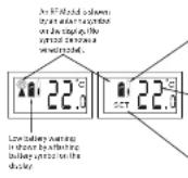
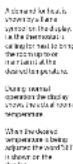
FEATURES
This product has the following user adjustable settings
- Required room temperature (temperature setpoint)
- Preset temperature setting - Advanced feature
- Minimum & Maximum temperature settings - Advanced feature
Simple Setting or Operating
To set the required room temperature
- The display normally shows the current room temperature to within 0.5°C
- To adjust the required temperature, turn the dial clockwise to increase or anti-clockwise to decrease, (1 click = 1°C), the LCD will display the temperature setpoint as it is being adjusted and 'SET' will be displayed. After a few seconds the display will return to normal operation and will display the actual room temperature.
While adjusting the temperature during normal operation, when you reach the maximum or minimum possible setting the display will flash to indicate you cannot adjust the product further.
ADVANCED FEATURES
Adjusting the Setpoint using the Preset Temperature Mode
Change the temperature at the press of a button, for example, if you are going out to the shops for an hour you can reduce the temperature to save energy and then when you press the button again on your return the setpoint will return to the previous level.
- To adjust the setpoint to the preset (or Setback) temperature, press the 'Set' button during normal operation and the product will go into Preset mode.
NB. This feature can be used to quickly adjust the temperature setpoint to a setback temperature for economy operation if for example. 'Preset Temperature = 15°C'. Or alternatively to a comfort setpoint if 'Preset Temperature = 21°C'.
- Once the setpoint has been changed to the preset (or setback) temperature by pressing 'Set' the display will show the 'Preset Temperature' and 'SET' will be flashing in the display as shown.

'5ET' will flash for approximately 5 seconds and during this time
the 'Preset Temperature' can be altered by rotating the dial.
- The product will remain in the Preset mode. Once 5 seconds have elapsed (since the last dial adjustment) the word 'SET' will stop flashing on the display as shown.

The product is still in the Preset mode.
To cancel the Preset Mode & return to normal operation
You can either,
- If you want to return to your previous setpoint (before you entered the Preset mode) then press the 'SET' button. The Preset mode will be cancelled and the product will return to normal operation and the display will show the current room temperature as shown.

- If you want to set a new setpoint, just rotate the dial until your
required setpoint is shown on the display. After a couple of seconds the display will change to show the current room temperature as
the display will change to show the current room temperature as shown.

To change the user adjustable settings
• To enter the 'User' menu, press and hold the 'Set' button for more than 5 but less than 10 seconds – the display will show 'Pr (Preset temperature setting) as shown.

- If the dial is turned clockwise one click then 'HI' (Maximum
temperature setting) will be displayed and if turned one more click clockwise then 'Lo' (Minimum temperature setting) will be displayed. Changing the Preset Temperature
• To adjust the 'Preset' temperature enter the user menu as
described above, then rotate the dial until "Pr" is shown, press the set button and the display will show the current Preset setting.

- Rotate the dial clockwise to increase the Preset temperature
& anti-clockwise to reduce the Preset temperature. Press the 'Set' button to confirm and 'Pr' will be displayed.

Changing the Maximum Temperature Setting
• To adjust the maximum temperature setting enter the user
menu as described above, then rotate the dial clockwise until 'III' is showing.

- Then press the 'Set' button, the current setting is shown.

- Rotate the dial clockwise to increase the maximum temperature setting (max.30°C) and anti-clockwise to reduce the maximum temperature setting (min.5°C or min. temp. setting). Press the 'Set' button to confirm, the display will show,

Changing the Minimum Temperature Setting
- To adjust the minimum temperature setting enter the user menu as described above, then rotate the dial clockwise until 'Lo'

- Then press the 'Set' button, the current setting is shown.

- Rotate the dial clockwise to increase the minimum temperature setting (max.30°C or max. temp. setting) and anti-clockwise to reduce the minimum temperature setting (min 5°C). Press the 'Set' button to confirm, the display will show.

While adjusting the settings within the menu, when you reach the maximum or minimum possible setting the display will flash to indicate you cannot adjust the product further, e.g. you cannot set the Preset higher than the maximum temperature setting.
To return to normal operation, either press the 'Set' button for more than 5sec or wait for 1 minute and it will return automatically.
TAMPER PROOFING (All Models)
To tamper proof the product i.e. prevent unauthorised adjustment of the product set the Min and Max temperatures to the same desired value.
FAULT DIAGNOSIS (All Models)
If the display shows E1, the following faults could have occurred
- Internal temperature sensor has failed.
2.Ambient temperature is outside product operating temperature range.

BATTERY REPLACEMENT (All Models)
- When the batteries are getting low (approx 30 days battery
the Refirming) the Battery symbol with hash in the display, it is recommended to change the batteries during this period. - After approx 30 days, a continuous battery symbol only will be
shown in the display and the unit will finish OFF.

How to replace the batteries
Remove battery compartment
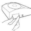
Remove the battery compartment by pinching the tabs and withdrawing downwards. Replace the spent batteries with 2 x AA 1.5V alkaline batteries ensuring correct orientation. Replace the battery compartment pressing fully home.
RF PRODUCT ONLY
SCR RECEIVER (RF Model only)
SCR (Receiver) Normal Operating Mode
+ Once the 'Wireless System' has been commissioned, there should
be little need for any user interaction with the SCR.
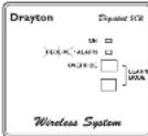
• During normal operation the red and green LEDs will occasionally
be an, these signify the following:
GREEN LED
The green LED will be on when there is a demand for heating, and off when there is no demand.
Red LED
The red LED will flash for 7 seconds, approximately every 5 minutes. This denotes that a radio signal is being received from the Digistat-RE unit.
Situations Requiring Attention
Red LED continually flashing
- This denotes that the batteries in the Digistat+RF unit are
approaching the end of their life (see 'battery replacement').
Red LED continually on
This denotes that the SCR has been unable to receive a radio signal from the Digistat+RF unit. This may be caused by the batteries being dead (see 'battery replacement') or some temporary interference with the radio signal.
To resend and test the signal, go to the Digistat-RF unit and open the battery drawer, after a few seconds (the display will go blank) close the battery drawer and then reset to your desired temperature. If the radio signal has been successfully transmitted and received, the red LED will flash for 7 seconds then go off.
- If the rod LED stays on, there may be some other fault that will require the attention of a heating engineer/electrician.
Manual Override
- The heating can be manually switched on and off by using the 'OVERRIDE' button on the SCR in a fault situation, even though the red LED will stay on until a satisfactory signal is reinstated. - Once the SCR receives a satisfactory signal again, it will automatically reset itself for normal operation.
RF PRODUCT ONLY
INSTALLATION OF SCR (RF Models only)
If you do not have the knowledge to install the SCR safely then you must arrange for a competent electrician to install it for you. Wiring must conform to the current IEE regulations.
Prior to commencing the installation you must ensure the mains supply is switched off.
Installation Instructions
Read all installation and commissioning instructions before proceeding.
Do not switch on until ready to commission.
The system wiring must be able to be fully disconnected from the mains supply by a switch incorporated in the fixed wiring having a contact separation of at least 3mm on both poles. Fused at 3A.
Location
The Digistat SCR (receiver) should be mounted in a convenient position, close to the combi boiler or central heating system wiring centre. (Care should be taken not to mount the SCR in a position
where it is surrounded by metal objects or mains voltage cable, as this may interfere with the radio signal).
Fixing (minimum wall plate clearances shown)
-
Loosen the securing screws, remove the wallplate, and if surface wiring is to be used, snap out the cable entry strip on the bottom edge of the wallplate with a pair of pliers.
-
Fix the wallplate, terminals at the top, either direct onto the flat wall using wall plugs and no 6 x1" wood screws or on a flush mounting single conduit box using M3.5 x 14 screws. Minimum wallplate clearances are shown.
-
Complete the wiring to the SCR wallplate in accordance with the relevant diagram, to comply with current IEE regulations.
-
Place the SCR onto the wallplate and tighten the securing screws.
SCR wallplate clearances
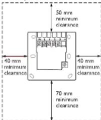
text_image
50 mm minimum clearance 40 mm minimum clearance 40 mm minimum clearance 70 mm minimum clearanceElectrical
flowchart
graph TD
    A["N.1"] --> B["230V AC 50Hz Fused 3A"]
    C["133"] --> D["Common"]
    E["Call for heat"] --> F["heating satisfied or call for cooling"]
    G["Volt free contacts"] --> H["Switch"]
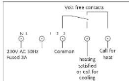
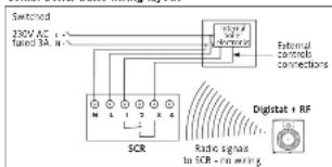
This product is double insulated and does not require an earth connection. The SCR should be wired to the comal boiler or central heating wiring using the correct type of cable or flex. The SCR should be wired in to replace hard wired room or programmable thermostats shown on the system or boiler wiring diagrams. Always check other manufacturers instructions for compatibility.
Combi boiler basic wiring layout
text_image
Switched 230V AC fained 5A SCR External controls connections Digital + RF Radio signals in SCR - in wiringZone control basic wiring layout
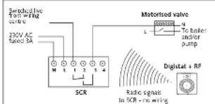
text_image
Switched live from wire gning candle 230V AC fused 5A SCR Motorised valve To boiler under pump Digital + RF Radio sign to SCR - no wiringCOMMISSIONING THE 'WIRELESS SYSTEM' (RF Models only) Standard for all models
IMPORTANT: MULTIZONE INSTALLATIONS ONLY If more than one 'wireless system' is fitted within the same property, ie. for controlling 2 or more zones (multi-zone) it is essential that the Digistat RF units are matched correctly to the relevant SCR. This is easily achieved by commissioning each Digistat and SCR in turn.
-
Install (see installation instructions) and turn power on to the SCR (receiver). If a separate programmer is fitted, ensure that it is switched on. The red LED should come on.
-
Push the 'override' button on the SCR once. The green LED should also come on. Check to see if the boiler and/or motorised valve are working.
-
To enter 'learn' mode push the button marked 1 followed by 2 (OVERRID) and hold both depressed together. The red LED should flash for 2 seconds and then go out signifying the SCR is in learn mode. Release both buttons.
-
The red and green LED's should both now be an
-
Take the Digistat RF and hold it within sight of the SCR (no closer than one metre).
-
Insert the batteries into the holder and slide them into the Digistat RF until the drawer clicks into place.
-
The Digistat RF should now display the actual room temperature. If the unit has been stored in a cold place, it may take time to warm up.
-
As soon as the battery compartment is slid back into place, the red LED on the SCR should flash for 7 seconds and then go out. The green LED may be on or off depending on the room temperature at the time of commissioning.
-
If the red LED remains on, slide down the battery drawer on the Digistat RF, check the battery positions are correct, and once the display has faded, repeat steps 6 to 8.
-
Increase the 'SET' temperature on the Digistat RF by rotating the dial clockwise until a flame symbol appears, in the left hand segment of the display.
-
The red LED on the SCR should flash for 7 seconds. This confirms that the radio signal is being sent and received. After 7 seconds the red LED should go out and the green one came on.
-
Check to confirm that the boiler and/or motorised valves are working.
-
Decrease the 'SET' temperature on the Digistat RF by rotating the dial anticlockwise until the flame symbol disappears.
-
The red LED on the SCR should flash for 7 seconds. After 7 seconds both the red and green LEDs should go out. Check that the boiler and/or motorised valve have powered down.
-
Place the Digistat RF in the chosen operating position, (see Digistat RF location section) and repeat steps 10 to 14. Once you have confirmed the system operates correctly, fit and secure the Digistat RF to the wall (see installation instructions).
During normal operation the red LED on the SCR will flash for 7 seconds each time a radio signal is received from the Digistat RF. This will occur approximately every 5 minutes.
The green LED on the SCR denotes a call of heat (ON).
Once the system has been successfully commissioned, buttons 1 and 2 on the SCR should not be pressed simultaneously, unless a replacement Digistat RF or SCR is fitted.