RTS4 - Thermostat Drayton - Kostenlose Bedienungsanleitung
Finden Sie kostenlos die Bedienungsanleitung des Geräts RTS4 Drayton als PDF.


Benutzerfragen zu RTS4 Drayton
0 Frage zu diesem Gerät. Beantworten Sie die, die Sie kennen, oder stellen Sie Ihre eigene.
Eine neue Frage zu diesem Gerät stellen
Laden Sie die Anleitung für Ihr Thermostat kostenlos im PDF-Format! Finden Sie Ihr Handbuch RTS4 - Drayton und nehmen Sie Ihr elektronisches Gerät wieder in die Hand. Auf dieser Seite sind alle Dokumente veröffentlicht, die für die Verwendung Ihres Geräts notwendig sind. RTS4 von der Marke Drayton.
BEDIENUNGSANLEITUNG RTS4 Drayton
Drayton
RTS Thermostat
Installation instructions
Models
RTS1: Standard heating thermostat
RTS2 Heating thermostat with call for heat LED indicator
RTS3: Indoor frost thermostat
RTS4 Volt free heating/cooling change over switch
RTS9 & 10: Volt free heating/cooling changeover switch with call for heating LED indicator
IMPORTANT NOTE
RTS thermostats are ELECTRONIC with a relay output. Unless connected to a 230V mains supply the relay will not operate, no 'click' will be heard and the call for heat contact will remain open.
Location
Care should be taken to mount the thermostat in a position which is not subject to direct sunlight or draughts. Preferably it should be mounted on an inside wall about 1.5m (5ft) above the floor in a position where it can respond to room temperature but away from the direct influence of radiators or other appliances giving off heat.
Note: If the thermostat is to be used as a frost protection device it should be located in the coldest part of the premises.
Fixing
- Loosen the securing screws, remove the wall-plate and, if surface wiring is to be used, snap out the cable entry strip on the bottom edge of the wall-plate with a pair of pliers.
- Fix the wall-plate, terminals at the top, either direct onto a flat wall using wall plugs and No 6 x 1" woodscrews or on a flush mounting single conduit box using M 3.5 x 14 screws.
- Complete the wiring to the wall-plate in accordance with the relevant diagram shown overleaf in accordance with I.E.E. regulations.
Note: The thermostat is for fixed wiring only and is double insulated, the earthing continuity (loop) terminal is only provided for convenience.
-
Plug the thermostat onto the wall-plate and tighten the securing screws.
-
Before switching on the mains ENSURE THE CIRCUIT FUSE IS 3A.
WARNING
Disconnect mains supply before fitting or removing from wall-plate.
A switch having contact separation of at least 3mm in all poles must be incorporated in the fixed wiring as a means of providing full disconnection of the mains supply.
Setting
- Set the desired room temperature on the control knob against the setting mark.
- The setting range may be limited or a particular setting locked through the use of the mechanism to be found under the control knob.
- To adjust the limiters firstly set the thermostat to the desired temperature and then carefully pull off the knob.
- Lift and rotate the two limiting arms to re-position them in the required notches.
- Replace the knob with the previously set temperature against the setting mark.
Technical data
Electrical supply: 230V ac 50Hz fused 3A Double insulated (no earth required)
Temp. range: RTS1, 2, 4 & 9 10° to 30°C RTS3 (Frost) 3° to 10°C RTS10 14° to 30°C Switch type: RTS 1, 2 & 3 S.P.S.T 2(1)A 230V ac live output RTS4, 9 & 10 S.P.D.T 2(1)A 230V ac volt free
Temp. sensor: Electronic
Wiring (schematic)
Note: It is essential to make a neutral connection to terminal N.
RTS1, RTS2 and RTS3
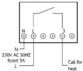
text_image
N L 3 N 23DV AC 50HZ fused 3A L Call for heatRTS4, RTS9 and RTS10

text_image
N L 1 2 3 N COM Call for heat 230V AC 50HZ fused 3A Heating satisfied or L call for coolingNote: Link between terminals L and 1 if mains voltage is required on the thermostat switch.
Information
The RTS room thermostat replaces earlier models of both ACL and Drayton room thermostats subject to a maximum load of 2(1)A 230V ac. The wiring conversion between these models is:
| ACL TS142 | ACL TA350 | Drayton Roomstat RT (E) | RTS 1,2 & 3 | RTS 4, 9, & 10 | |
| Live supply | 1 | - | 1 | L | L |
| Neutral (accelerator heater) | 4 | - | 4 | N | N |
| Call for heat | 2 | 3 | 2 | 3 | 3 |
| Heating satisfied (call for cooling) | - | 2 | 3 | - | 2 |
| Volt free switch common | - | 1 | -- | 1 | |
| Earth connection | E | 5 | - | - | - |
Conforms to the essential requirements of the following directives:
Relevant EC Directives Energy Class: IV - 2% 2006/95/EC Low Voltage Directive (According to EU 2004/108/EC Electromagnetic 811/2013, 812/2013, Compatibility Directive 813/2013, 814/2013) 2011/65/EU RoHS Directive
Applied Standards EN60730-1, EN60730-2-9
Room thermostats
| Make Model | Earth | Neutral | Live | Common | Demand | Satisfied | |
| Drayton RTS 1 & 2 N L 3 | |||||||
| Drayton RTS 4, 5, 9 & 10 | N | L 1 | 3 | 2 | |||
| ACL Lifestyle PT271/371 | N | L 1 | 3 | 2 | |||
| ACL Lifestyle TS 142 | E 4 | 1 2 | |||||
| ACL Lifestyle | TA 350 | 5 | 1 | 3 | 2 | ||
| Drayton Digistat (old version) | 4 | 1 | 2 | 3 | |||
| Drayton RT & RTE | 4 | 1 | 2 | 3 | |||
| Danfoss Randall | TP1 | E | N | L | 1 | 2 | |
| Danfoss Randall | RT1, TP2, 3, 4 & 5 | 1 | 3 | 2 | |||
| Danfoss Randall | RD3, RD3A | 4 | 1 2 | ||||
| Danfoss Randall | RTC, RTM, RSR | E | N | 3 | 1 | 2 | |
| Danfoss Randall | R504 | N | 3 | 1 | 2 | ||
| Honeywell | 6060, 6061, 6063 | 2 | 1 | 3 | 4 | ||
| Honeywell | CT200 | A | B | C | |||
| Horstman | HRT 1 | E 4 | 1 2 | ||||
| Landis & Gyr | RAD 1 | E | 1 | 2 | 3 | ||
| Potterton | PRT 1 | N | L | H | |||
| Potterton | PRT 2 & 100 ST | N | TL | H | |||
| Potterton | PRT 100 DT | N | TL | H | C | ||
| Sunvic | TLX 2259 | E | N | L | 1 | 2 | |
| Sunvic | TLX 2356 | E | 3 | 1 | 2 | ||
| Sopac | TA 350 | E | 1 | 3 | 2 | ||
| Sopac | TA 351 | E | 4 | 1 | 3 | 2 | |
| Switchmaster | SRT 2 5 | 1 | 3 | 2 | |||
| Tower | SS | E 4 | 1 2 | ||||