BSW-1700 - Heimtrainer Body Sculpture - Kostenlose Bedienungsanleitung
Finden Sie kostenlos die Bedienungsanleitung des Geräts BSW-1700 Body Sculpture als PDF.


Benutzerfragen zu BSW-1700 Body Sculpture
0 Frage zu diesem Gerät. Beantworten Sie die, die Sie kennen, oder stellen Sie Ihre eigene.
Eine neue Frage zu diesem Gerät stellen
Laden Sie die Anleitung für Ihr Heimtrainer kostenlos im PDF-Format! Finden Sie Ihr Handbuch BSW-1700 - Body Sculpture und nehmen Sie Ihr elektronisches Gerät wieder in die Hand. Auf dieser Seite sind alle Dokumente veröffentlicht, die für die Verwendung Ihres Geräts notwendig sind. BSW-1700 von der Marke Body Sculpture.
BEDIENUNGSANLEITUNG BSW-1700 Body Sculpture
USER'S MANUAL
natural_image
Technical line drawing of a bicycle support structure with no visible text or symbolsImportant Safety Information
Please keep this manual in a safe place for reference.
-
It is important to read this entire manual before assembling and using the equipment. Safe and efficient use can only be achieved if the equipment is assembled, maintained and used properly. It is your responsibility to ensure that all users of the equipment are informed of all warnings and precautions.
-
Before starting any exercise program you should consult your doctor to determine if you have any physical or health conditions that could create a risk to your health and safety, or prevent you from using the equipment properly. Your doctor's advice is essential if you are taking medication that affects your heart rate, blood pressure or cholesterol level.
-
Be aware of your body's signals. Incorrect or excessive exercise can damage your health. Stop exercising if you experience any of the following symptoms: Pain, tightness in your chest, irregular heartbeat, extreme shortness of breath, feeling light headed, dizzy or nauseous. If you do experience any of these conditions you should consult your doctor before continuing with your exercise program.
-
Keep children and pets away from the equipment. The equipment is designed for adult use only.
-
Use the equipment on a solid, flat level surface with a protective cover for your floor or carpet. For safety, the equipment should have at least 0.5 metre of free space all around it.
-
Before using the equipment, check the nuts and bolts are securely tightened.
-
The safety level of the equipment can only be maintained if it is regularly examined for damage and/or wear and tear.
-
Always use the equipment as indicated. If you find any defective components whilst assembling or checking the equipment, or if you hear any unusual noise coming from the equipment during use, stop. Do not use the equipment until the problem has been rectified.
-
Wear suitable clothing whilst using the equipment. Avoid wearing loose clothing which
may get caught in the equipment or that may restrict or prevent movement.
-
The equipment has been tested and certified to EN957 under class H.C. Suitable for domestic, home use only. Maximum weight of user, 100kg. Breaking is speed independent.
-
The equipment is not suitable for therapeutic use.
-
Care must be taken when lifting or moving the equipment so as not to injure your back. Always use proper lifting techniques and/or use assistance.
If you experience any problems or require assistance, please contact our customer services on 01274 693888. This is only available for UK resident.
natural_image
Line drawing of a bicycle walker frame with adjustable arms and legs (no text or symbols)
natural_image
Abstract grayscale texture with a small number '1' in the upper right corner (no text or symbols)Expanded Assembly Diagram
text_image
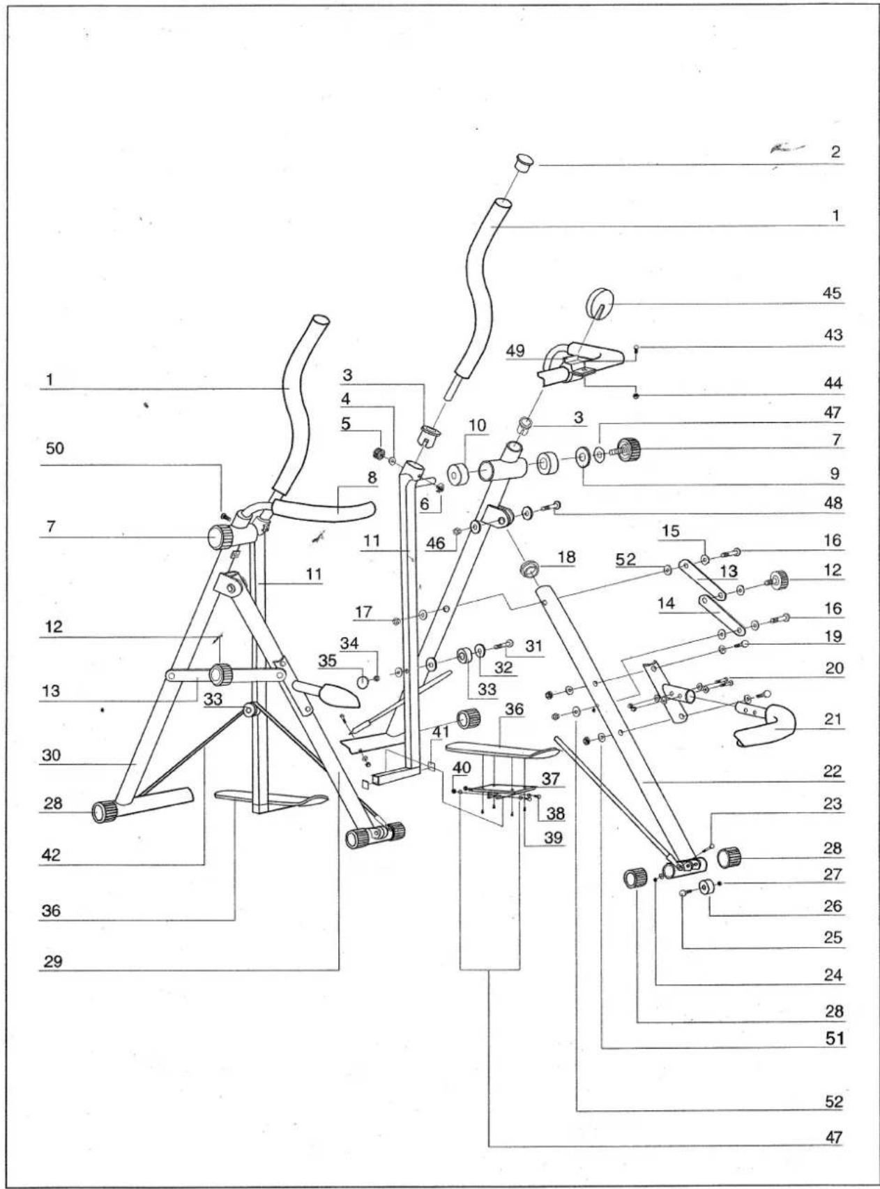
Technical diagram of a mechanical device with numbered components for identification| PART LIST | |||||
| NO. | DESCRIPTION | QTY | NO. | DESCRIPTION | QTY |
| 1. | Foam Grip | 2 | 27. | Nut | 2 |
| 2. | Round End CAP | 2 | 28. | End Cap | 6 |
| 3. | Tube Insert | 2 | 29. | Front Supporting Frame (right) | 1 |
| 4. | Washer | 2 | 30. | Rear Supporting Frame | 1 |
| 5. | Locking Knob | 2 | 31. | Fixing Bolt | 2 |
| 6. | Fixing Screw | 2 | 32. | Washer | 4 |
| 7. | Adjustable Knob | 2 | 33. | Bushes | 2 |
| 8. | Upper Safety Bar | 1 | 34. | Nut | 2 |
| 9. | Washer | 2 | 35. | Nut Cover | 2 |
| 10. | Bushes | 4 | 36. | Pedal | 2 |
| 11. | Leg Support | 2 | 37. | Foot Rest | 2 |
| 12. | Fixing Knob | 2 | 38. | Fixing Bolt (M8x45mm) | 4 |
| 13. | Parallel Bar (a) | 2 | 39. | Fixing Screw | 8 |
| 14. | Parallel Bar (b) | 2 | 40. | Nut (M8) | 4 |
| 15. | Washer | 8 | 41. | End Cap | 4 |
| 16. | Fixing Bolt | 4 | 42. | Tension Band | 2 |
| 17. | Nut | 4 | 43. | Fixing Screw | 1 |
| 18. | End Cap | 2 | 44. | Nut | 1 |
| 19. | Hex-Head Bolt (M8x60mm) | 4 | 45. | Computer | 1 |
| 20. | Fixing Bolt | 4 | 46. | Nut | 2 |
| 21. | Lower Safety Bar | 1 | 47. | Washer | 10 |
| 22. | Front Supporting Frame (left) | 1 | 48. | Bolt | 2 |
| 23. | Fixing Bolt | 4 | 49. | Computer Holder | 1 |
| 24. | Nut | 4 | 50. | Screw (M6x16mm) | 2 |
| 25. | Fixing Bolt | 2 | 51. | Curve Washer | 8 |
| 26. | Transportation Wheel | 2 | 52. | Washer (M10) | 8 |
ASSEMBLY INSTRUCTION
text_image
22 30 12
text_image
21 19 51 51 51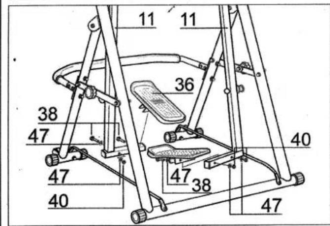
text_image
11 11 36 38 47 40 47 47 40 47 38 40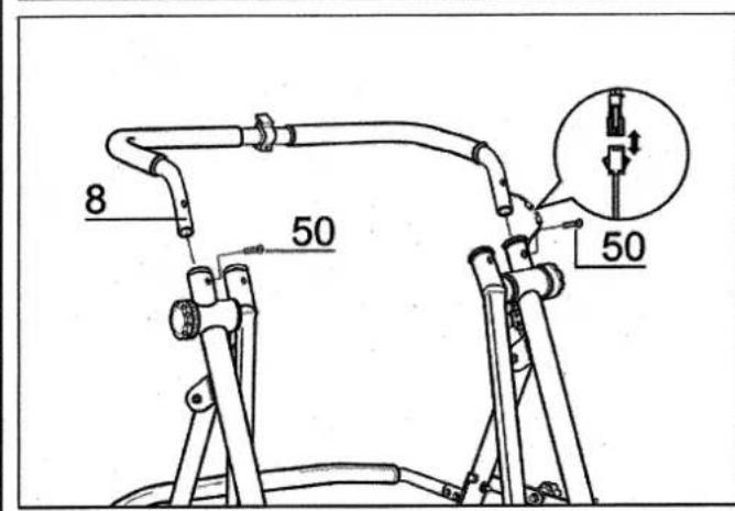
text_image
8 50 50STEP 1
To assemble main supporting frame:
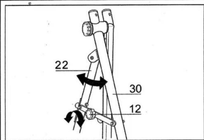
Unscrew the locking knob(12), extend the front and rear supporting frame(22 &30 ), then press down the parallel bars until they are straight and re-tighten the locking knobs(12) (See Figurel).
STEP 2
To assemble lower safety bar to the main supporting frame:
Connect lower safety bar (21) onto front of the frame. N B. The holes on the safety bar bracket correspond with the holes in the front leg of the main supporting frame.
Secure the safety bar by placing the 4xbolts (19) (M8x60mm) through the holes of the safety bar and frame. The curve washers (51) should be inserted on the bolt head side as well as nut side.
STEP 3
To assemble the foot pedals to the leg supports:
The foot pedal(36) is pre-fastened to the molded foot rest and will be in the correct position when the upward curve is facing the lower safety bar. The left and right pedals are interchangeable. Place one pedal over each leg support and fasten using 4 x hex-head bolts(38), 8 x washers(47) and 4 x nuts(40) as shown in Figure 3. The washers should be placed on the outside part of the bracket, on the bolt head side and nut side. Securely fasten so that the pedals do not shift.
STEP 4
To assemble the upper safety bar:
Thread the sensor cable through the hole at the centre of the upper safety bar (8) through to the end of the bar. The cable should be fed through the right side as shown in Figure 4. Connect the data cable to the sensor cable by gently pushing them together. Assemble the upper safety bar (8) to the main frame by using 2x(M6x12mm) screws(50).
text_image
Technical diagram showing a mechanical assembly with a magnified inset highlighting a component detail.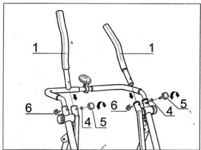
text_image
1 1 6 4 5 6 4 5 5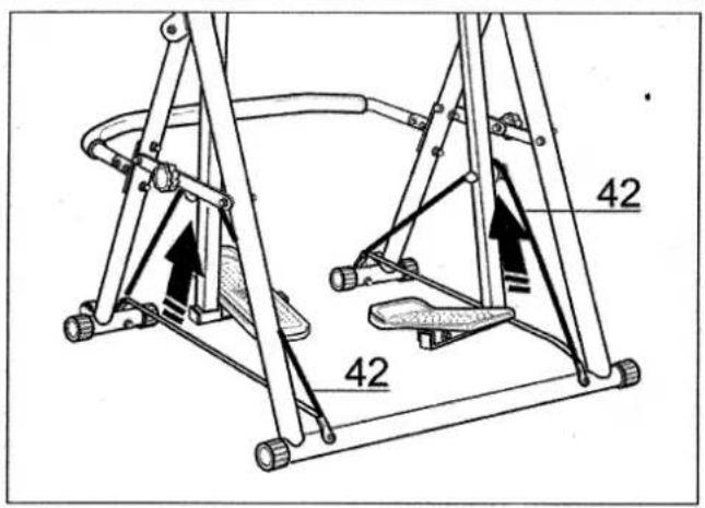
text_image
42 42STEP 5
To connect the computer to the main supporting frame:
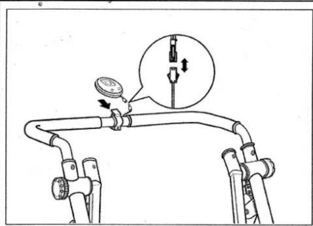
Attach the computer holder by using screw provided. Slide the computer onto the bracket As the machine is in operation, a magnet which is attached to the right leg post will pass by the sensor and send a signal to the computer. The magnet and sensor do not make contact but they should be close to each other.
STEP 6
To assemble gliding poles to main supporting frame: Slide the gliding poles (1) into the main supporting body as shown in Figure 6.
Secure each pole with one locking knob (5) and washer(4) by screw(6) through pole support. (Bracket should fit into slots in the main supporting frame.)
Tighten the gliding poles with the locking knobs (5) provided.
STEP 7
The tensional bands:
Lift the tension bands (42) into place by stretching them over the pulley mounted on the left and right leg supports as shown in Figure 7.
EXERCISE INSTRUCTIONS
Using your Aero Strider Xtra will provide you with several benefits; it will improve your physical fitness, tone the calves, thighs, buttocks and waist, and in conjunction with a calorie - controlled diet, help you lose weight. N.B. Always consult your physician before engaging in any exercise programme.
1.The Warm Up Phase
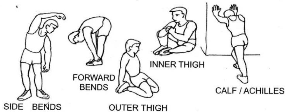
This stage helps get the blood flowing around the body and the muscles working properly. It will also reduce the risk of cramp and muscle injury. It is advisable to do a few stretching exercises as shown below. Each stretch should be held for approximately 30 seconds, do not force or jerk your muscles into a stretch - if it hurts, STOP.
Straddle the foot plates of the aero strider and hold onto the arms. Place your right foot on the right footplate, your left foot on the left footplate and when you feel comfortable and balanced you can slowly begin the warm up. Push your right foot forward (right arm back) approximately 1 meter and your left foot back (left arm forward) the same distance remembering to keep your knees slightly bent at all times. Reverse the movement - bring the left foot forward and push the right foot back, it is not necessary to use the full extension of the leg supports for the warm up. Repeat these movement for approximately 5 minutes.
text_image
SIDE BENDS FORWARD BENDS OUTER THIGH INNER THIGH CALF / ACHILLES2. The Exercise Phase
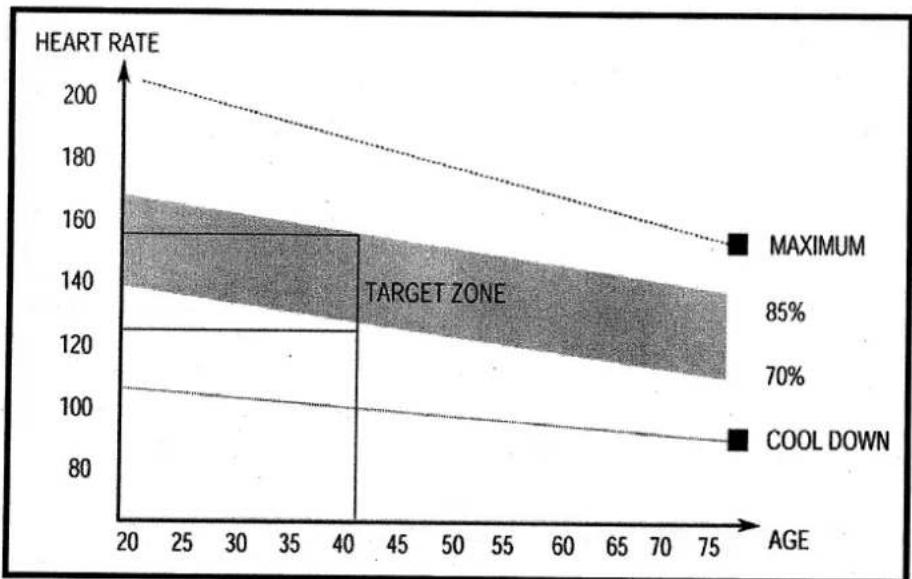
This is the stage where you put the effort in. After regular use, the muscles in your legs will become more flexible. Work your arms and legs in conjunction with each other and remember to keep your knees slightly bent. Work to your own pace but it is very important to maintain a steady tempo throughout. The rate of work should be sufficient to raise your heart beat into the target zone shown on the graph below.
line
| AGE | HEART RATE | | --- | --- | | 20 | 200 | | 40 | 160 | | 75 | 120 |This stage should last for a minimum of 12 minutes though most people start at about 15-20 minutes
3. The Cool Down Phase
This stage is to let your Cardio Vascular System and muscles wind down. This is a repeat of the warm up exercise e.g. reduce your stride and tempo, continue for approximately 5 minutes. The stretching exercises should now be repeated, again remembering not to force or jerk your muscles into the stretch. As you get fitter you may need to train longer and harder. It is advisable to train at least three times a week, and if possible space your workouts evenly throughout the week.
4. WEIGHT LOSS
The important factor here is the amount of effort you put in. The harder and longer you work, the more calories you will burn. Effectively this is the same as if you were training to improve your fitness, the difference is the goal.
SAFETY
- Make sure all parts are secure before using your AERO STRIDER XTRA, if necessary tighten any loose nuts and bolts.
- Always consult your physician before engaging in any exercise program.
- Always wear sensible clothing and footwear while exercising.
- Do not let children around the machine whether it is in use or not.
- Do not exercise within 2 hours of eating a large meal, or for one hour before.
- Keep hold of the handles at all times while using the AERO STRIDER XTRA.
- Only use the AERO STRIDER XTRA in a clear space, make sure there is nothing directly behind the AERO STRIDER XTRA which could be an obstruction when getting on or off.
- Exercise should be stopped if any of the following occur: Nausea, Trembling, Extreme Shortness of Breath, Excessively Fast Heart Rate, A Throbbing Head or Pains in the Chest. Your physician should be consulted if any of the symptoms of discomfort persist.
MAINTENANCE
Inspect and tighten all parts each time you use your AERO STRIDER XTRA. Replace all worn parts immediately.
Your AERO STRIDER XTRA can be cleaned using a damp cloth and a mild detergent. Do not use solvents or abrasives.
To preserve the smooth action of your AERO STRIDER XTRA, we recommend that you periodically grease all pivot shafts using a silicone or lithium grease.
EXERCISE COMPUTER
FUNCTION BUTTONS:
MODE PRESS TO SELECT ARROW SIGN DIRECT TO EACH FUNCTION BETWEEN COUNT, TIME, CAL, STRIDES/MIN, SCAN. OR HOLD ON FOR 3 SECONDS TO HAVE ALL FUNCTION VALUES BE TOTAL RESET.
RESET PRESS TO RESET ALL FUNCTION VALUES.
FUNCTIONS:
COUNT ACCUMULATES THE NUMBERS OF STIRDE DURING WORKOUT SESSIONS.
TIME COUNTS FROM ZERO UP TO 99:59 IN ONE SECOND INCREMENT.
CALORIES ACCUMULATES CALORIES CONSUPMTION DURING EXERCISE. THIS IS A ROUGH GUIDE ONLY AND SHOULD BE USED AS COMPARISON OVER SEVERAL EXERCISE SESSIONS.
STRIDES/MIN DISPLAYS STRIDES IN EVERY MINUTE.
SCAN AUTOMATICALLY SCANS EACH FUNCTION IN SEQUENCE.
NOTE:
- TO TURN ON THE POWER, JUST PRESS ANY BUTTON OR START EXERCISING.
- IF THE EXERCISE STOPS FOR 6 SECONDS, "STOP" SIGN WILL APPEAR ON THE MONITOR. FUNCTION DATAS WILL BE KEPT AND COUNT UP FROM PREVIOUS DATAS WHEN THE EXERCISE STARTS.
- WITH NO SIGNAL TRANSMITTED INTO THE COMPUTER FOR 4 MINUTES, THE COMPUTER WILL SHUT OFF THE LCD DISPLAY AUTOMATICALLY, AND ALL FUNCTION VALUES WILL BE RESERVED. AS SOON AS THERE IS SIGNAL TRANSMITTED IN, THE LCD WILL DISPLAY THE RESERVED VALUES AND START COUNTING FROM THESE VALUES.
- THE COMPUTER OPERATES WITH 1.5V, AA SIZE BATTERY x 1 PC.

text_image
BODY® SCULPTURESINCE 1965
COPYRIGHT ©2002 BY BODY SCULPTURE INTERNATIONAL EUROPE LTD ALL RIGHTS RESERVED.UNAUTHORIZED DUPLICATION IS A VIOLATION OF LAW.