
IC-32AT - Empfänger ICOM - Kostenlose Bedienungsanleitung
Finden Sie kostenlos die Bedienungsanleitung des Geräts IC-32AT ICOM als PDF.


Benutzerfragen zu IC-32AT ICOM
0 Frage zu diesem Gerät. Beantworten Sie die, die Sie kennen, oder stellen Sie Ihre eigene.
Eine neue Frage zu diesem Gerät stellen
Laden Sie die Anleitung für Ihr Empfänger kostenlos im PDF-Format! Finden Sie Ihr Handbuch IC-32AT - ICOM und nehmen Sie Ihr elektronisches Gerät wieder in die Hand. Auf dieser Seite sind alle Dokumente veröffentlicht, die für die Verwendung Ihres Geräts notwendig sind. IC-32AT von der Marke ICOM.
BEDIENUNGSANLEITUNG IC-32AT ICOM
INSTRUCTION MANUAL
DUAL.BAND
FM TRANSCEIVER
IC-32AT
IC-32A
IC-32E
Icom Inc.
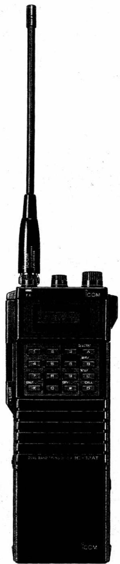
text_image
COM TX COM 1 2 3 A 4 5 B W/U 7 8 9 C DN/ DV CALL C D DUE RAND TRANSPORTIC - 12"AT DCOMTABLE OF CONTENTS
-
CAUTIONS.... 1
-
FEATURES.... 2
-
MODE CONSTRUCTION .... 3
-
CONTROL FUNCTIONS.... 5
4-1 TOP PANEL 5
4-2 FRONT PANEL 6
4-3 SIDE PANEL....6
4-4 FUNCTION DISPLAY 7
4-5 KEYBOARD 9
- PRE-OPERATION....71
5-1 CHARGING THE BATTERY PACK.....11
5-2 ANTENNA CONNECTION....13
5-3 HANDSTRAP ATTACHMENT.....13
5-4 BELT CLIP ATTACHMENT.....13
- BASIC OPERATION.... 14
6-1 FREQUENCY SETTINGS....14
6-2 RECEIVING. 17
6-3 TRANSMITTING....18
6-4 REPEATER OPERATION ..... 19
- MEMORY AND CALL OPERATIONS..... 20
7-1 MEMORY CHANNEL SELECTION .....20
7-2 MEMORY WRITING 23
7-3 MEMORY TRANSFERRING 23
7-4 CALL CHANNEL OPERATION .....24
- SCAN AND WATCH OPERATIONS ..... 26
8-1 FULL BAND SCAN. 26
8-2 PROGRAMMED SCAN 27
8-3 MEMORY SCAN. 28
8-4 SELECTED BAND MEMORY SCAN .....29
8-5 SKIP FUNCTION 30
8-6 PRIORITY WATCH....31
- SPECIAL FUNCTIONS.... 37
9-1 FULL DUPLEX OPERATION.....37
9-2 POCKET BEEP AND TONE SQUELCH FUNCTIONS 41
9-3 BEEP TONE FUNCTION .....42
9-4 LOCK FUNCTION. 42
- SET MODE.... 43
10-1 SET MODE CONSTRUCTION .....43
10-2 SUBAUDIBLE TONE....44
10-3 OFFSET FREQUENCY....45
10-4 TUNING STEP....45
10-5 SCAN EDGES 46
10-6 POWER SAVER....47
-
MAINTENANCE.... 48
-
SPECIFICATIONS 51
1. CAUTIONS

text_image
A S O THINNENEVER use strong cleaning agents such as benzine or thinner on the transceiver.
natural_image
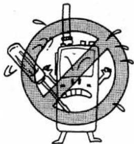
Cartoon illustration of a smartphone with a syringe and a face, surrounded by motion lines (no text or symbols)NEVER disassemble the transceiver as it may cause trouble.
natural_image
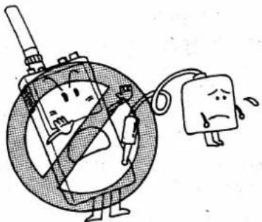
Cartoon illustration of a person holding a device connected to a sad block with a bandage, no text or symbols presentNEVER use chargers other than those suggested on p. 11.
natural_image
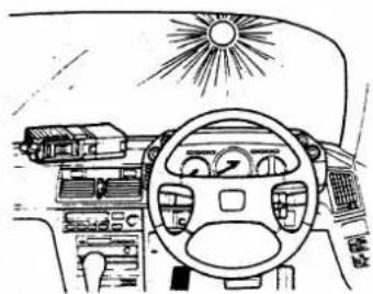
Interior view of a car dashboard with sunburst light overhead (no text or symbols)NEVER leave the transceiver on the dashboard in direct sunlight for long periods.

natural_image
Cartoon character with a basketball hit above his head, surrounded by radiating lines and expressive gestures (no text or symbols)AVOID using the transceiver for long periods in direct sunlight.

natural_image
Cartoon illustration of a snowman in winter gear standing beside a snowman, with bubbles and snowflakes (no text or symbols)AVOID using the transceiver in places subject to excessive cold.

natural_image
Cartoon illustration of a person holding a fan with smoke, surrounded by clouds (no text or symbols)AVOID using the transceiver in excessively dusty places.
natural_image
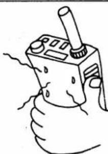
Hand holding a handheld device with a stick and lever, no visible text or symbolsBE CAREFUL when transmitting the transceiver for a long time, as the rear panel may become very hot.
FEATURES 2.
| ■ DUAL BAND CAPABILITY | The IC-32A/AT/E made it possible to operate both VHF (144MHz) and UHF (430 or 440MHz) bands from your palm. Without taking along two transceivers, QSY from crowded 144MHz band to uncrowded 430 or 440MHz band is very easy. |
| ■ FULL DUPLEX CAPABILITY | The transceiver provides simultaneous receive and transmit operation on VHF and UHF bands. While receiving on VHF band, for example, you can transmit on the UHF band. |
| ■ HIGH OUTPUT POWER | Full 5.5W on VHF and 5W on UHF band are available with BP-7 or BP-70 BATTERY PACK. |
| ■ NUMEROUS MEMORY CHANNELS | The transceiver equipped with 20 memory channels and 2 CALL channels. Each memory channel and CALL channel can independently memorize operating frequencies, repeater and other information. |
| ■ SCAN AND PRIORITY WATCH FUNCTIONS | Full band scan, programmed scan, memory scan, selected band memory scan and priority watch function are provided with the transceiver. |
| ■ QUICK FREQUENCY SELECTION | The transceiver is equipped both MAIN DIAL and KEYBOARD for quick frequency and memory channel selection. |
| ■ SPLASH RESISTANT | Rubber gaskets ensure that water splashed on the transceiver does not penetrate the casing. |
| ■ POCKET BEEP FUNCTION | This convenient pocket beep function lets you know when subaudible tones identical to your own pre-programmed ones arrive at the transceiver. Just install the optional UT-40 TONE SQUELCH UNIT in the transceiver to activate the function. |
| ■ POWER SAVER | The power saver functions if no signal is received or no switch operation is performed for more than 30sec. and requires only 1/4 current flow during regular receiving conditions. |
3. MODE CONSTRUCTION
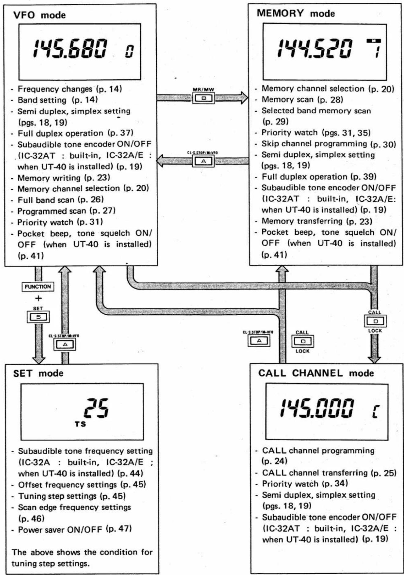
The transceiver has 4 different modes for versatile, multi-function operations. Following are explanations of each mode.
(1) VFO MODE
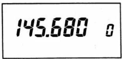
text_image
145.680 oThis mode is used for VFO frequency operations using all bandwidths.
Two VFOs are provided for VHF and UHF operations.
(2) MEMORY MODE
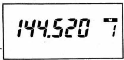
text_image
144.520 7This mode is used for operating the transceiver using memory channel contents.
The transceiver has 20 double space memory channels. One space for operating and subaudible tone frequencies and the other for full duplex or offset frequency.
(3) CALL CHANNEL MODE
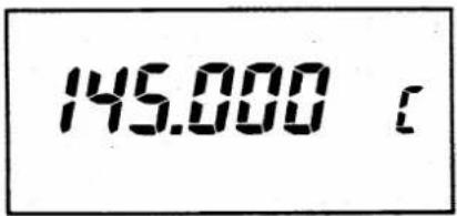
text_image
145.000 cThis mode is used for operating the transceiver on a programmed CALL channel. The transceiver has 2 CALL channels for VHF and UHF bands separately.
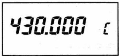
text_image
430.000(4) SET MODE
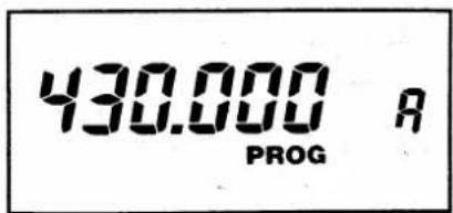
text_image
430.000 A PROGThis mode is used for programming subaudible tone frequency, ^* tuning steps, programmed scan edges and the power saver ON/OFF.
* IC-32AT : Built-in.
IC-32A/E : When the optional UT-40 TONE SQUELCH UNIT is installed.
MODE CONSTRUCTION 3.
flowchart
graph TD
    A["VFO mode"] --> B["Frequency changes (p. 14)"]
    A --> C["Band setting (p. 14)"]
    A --> D["Semi duplex, simplex setting (pgs. 18, 19)"]
    A --> E["Full duplex operation (p. 37)"]
    A --> F["Subaudible tone encoder ON/OFF (IC-32AT : built-in, IC-32A/E : when UT-40 is installed) (p. 19)"]
    A --> G["Memory writing (p. 23)"]
    A --> H["Memory channel selection (p. 20)"]
    A --> I["Full band scan (p. 26)"]
    A --> J["Programmed scan (p. 27)"]
    A --> K["Priority watch (p. 31)"]
    A --> L["Pocket beep, tone squelch ON/OFF (when UT-40 is installed) (p. 41)"]
    M["MEMORY mode"] --> N["Memory channel selection (p. 20)"]
    M --> O["Memory scan (p. 28)"]
    M --> P["Selected band memory scan (p. 29)"]
    M --> Q["Priority watch (pgs. 31, 35)"]
    M --> R["Skip channel programming (p. 30)"]
    M --> S["Semi duplex, simplex setting (pgs. 18, 19)"]
    M --> T["Full duplex operation (p. 39)"]
    M --> U["Subaudible tone encoder ON/OFF (IC-32AT : built-in, IC-32A/E: when UT-40 is installed) (p. 19)"]
    M --> V["Memory transferring (p. 23)"]
    M --> W["Pocket beep, tone squelch ON/OFF (when UT-40 is installed) (p. 41)"]
    X["SET mode"] --> Y["Subaudible tone frequency setting (IC-32A : built-in, IC-32A/E : when UT-40 is installed) (p. 44)"]
    X --> Z["Offset frequency settings (p. 45)"]
    X --> AA["Tuning step settings (p. 45)"]
    X --> AB["Scan edge frequency settings (p. 46)"]
    X --> AC["Power saver ON/OFF (p. 47)"]
    AD["CALL CHANNEL mode"] --> AE["CALL channel programming (p. 24)"]
    AD --> AF["CALL channel transferring (p. 25)"]
    AD --> AG["Priority watch (p. 34)"]
    AD --> AH["Semi duplex, simplex setting (pgs. 18, 19)"]
    AD --> AI["Subaudible tone encoder ON/OFF (IC-32AT : built-in, IC-32A/E : when UT-40 is installed) (p. 19)"]
    AJ["The above shows the condition for tuning step settings."] --> AK["FUNCTION"]
    AJ --> AL["SET"]
    AJ --> AM["A"]
    AJ --> AN["A"]
    AJ --> AO["A"]
    AJ --> AP["A"]
    AJ --> AQ["A"]
    AJ --> AR["A"]
    AJ --> AS["A"]
    AJ --> AT["A"]
    AJ --> AU["A"]
    AJ --> AV["A"]
    AJ --> AW["A"]
4. CONTROL FUNCTIONS
4 - 1 TOP PANEL
text_image
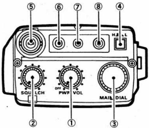
⑤ ⑥ ⑦ ⑧ ④ SQU LCH OFF PWR VOL MAIL DIAL ② ① ③① POWER/VOLUME CONTROL [PWR/VOL]
Turns ON and OFF the power and varies the audio level. (p. 14)
② SQUELCH CONTROL [SQUELCH] (IC-32A/AT)
Sets the squelch threshold point. (p. 17)
SQUELCH CONTROL AND TONE CALL SWITCH [SQL/PUSH T.CALL] (IC-32E)
Sets the squelch threshold point. (p. 17)
Transmits a 1750Hz tone for repeater operation. (p. 19)
③ MAIN DIAL [MAIN DIAL]
Changes the frequency and memory channel.
(pgs. 14, 20)
Performs dial select function. (pgs. 16, 20)
④ RF OUTPUT POWER SWITCH [H/L]
Selects RF output power. (p. 18)
⑤ ANTENNA CONNECTOR
Connect an antenna here. (p. 13)
⑥ EXTERNAL SPEAKER
JACK [EXT SP]
Accepts an optional HM-46 SPEAKER-MICROPHONE or earphone.
⑦ EXTERNAL MICROPHONE JACK [MIC]
Accepts an optional HM-46 SPEAKER-MICROPHONE.
⑧ EXTERNAL DC POWER JACK [DC IN 13.8V]
Accepts to connect external 12 \~ 15V DC power source. (p. 11)
CONTROL FUNCTIONS 4.
4 - 2 FRONT PANEL
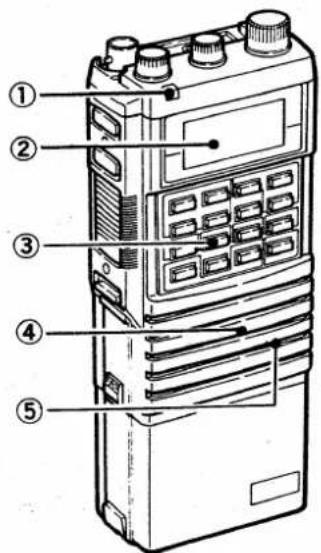
text_image
Diagram of a handheld device with numbered parts labeled 1 to 5, showing internal components and function keys.4 - 3 SIDE PANEL
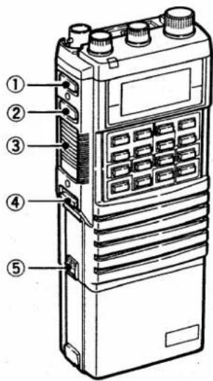
text_image
Diagram of a walk-in electronic device with labeled parts including control panel, display screen, and buttons① TRANSMIT INDICATOR [TX]
Lights when transmitting. (p. 18)
② FUNCTION DISPLAY
See Section 4 - 4 FUNCTION DISPLAY.
③ KEYBOARD
See Section 4 - 5 KEYBOARD.
④ SPEAKER
⑤ MICROPHONE
① MONITOR SWITCH [MONITOR]
Opens the squelch; and also the tone squelch (when UT-40 is installed). (p. 17)
The transmit frequency can be monitored during semi or full duplex operation. (pgs. 19, 38)
② FUNCTION SWITCH [FUNCTION]
When pushed and held, selects the secondary function of the KEYBOARD or dial select function. (pgs. 10, 16, 20)
③ PTT SWITCH
Selects transmitting. (p. 18)
④ LIGHT SWITCH [LIGHT]
Lights the FUNCTION DISPLAY. The backlight goes out after 5sec. if the KEYBOARD or MAIN DIAL are not operated.
⑤ BATTERY PACK RELEASE BUTTON [RELEASE]
Release the battery pack from the transceiver while pushed upwards. (p. 11)
4. CONTROL FUNCTIONS
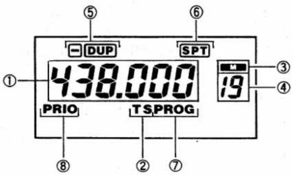
4-4 FUNCTION DISPLAY
text_image
① ⑤ - DUP ⑥ SPT 438.000 PRIO TSPROG ⑧ ② ⑦ M 19 ③ ④① FREQUENCY DISPLAY
Shows the operating frequency. (p. 14)
Shows programmed contents in SET mode. (p. 43)
② TS INDICATOR "TS"
"TS" blinks when tuning step setting in SET mode. (p. 45)
③ MEMORY MODE INDICATOR "M"
"M" appears in MEMORY mode. (p. 20)
④ MEMORY CHANNEL INDICATOR
Shows the memory channel number in VFO and MEMORY modes. (p. 20)
"C" appears in CALL CHANNEL mode. (p. 24)
⑤ DUPLEX INDICATORS “-” “DUP”
"DUP" or "−DUP" appears during semi duplex operation. (p. 19)
⑥ FULL DUPLEX INDICATOR "SPT"
"SPT" appears during full duplex operation. (p. 38)
⑦ PROGRAMMED SCAN INDICATOR "PROG"
"PROG" blinks while programmed scan. (p. 27)
Also blinks in scan edge settings of SET mode. (p. 46)
⑧ PRIORITY WATCH INDICATOR "PRIO"
"PRIO" appears in priority watch. (p. 31)
"PRIO" blinks when the transceiver receives a signal in watching channel. (p. 32)
CONTROL FUNCTIONS 4.
text_image
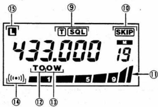
⑮ ⑨ ⑩ L T SQL SKIP 433.000 79 TOOW ((1•)) 1 5 9 ⑪⑨ TONE AND SQUELCH INDICATORS "T" "SQL"
"T" appears when the subaudible tone encoder is turned ON (IC-32AT; or IC-32A/E with UT-40). (p. 19)
"SQL" appears when an optional pocket beep function is turned ON (when the UT-40 is installed). (p. 41)
"T SQL" appears when an optional tone squelch function is turned ON (when UT-40 is installed). (p. 41)
⑩ MEMORY SKIP INDICATOR "SKIP"
"SKIP" appears when the displayed memory channel is programmed as a skip channel. (p. 30)
⑪ S/RF INDICATOR
Shows signal strength in receiving and selection of HIGH or LOW output power in transmitting. (pgs. 17, 18)
⑫ TONE SETTING INDICATOR "TO"
"TO" blinks in subaudible tone setting of SET mode (IC-32AT; or IC-32A/E with UT-40). (p. 44)
⑬ OFFSET FREQUENCY WRITE INDICATOR "OW"
"OW" blinks while offset frequency writing in SET mode. (p. 45)
⑭ POCKET BEEP INDICATOR “( ( ( · ) ) )”
While optional pocket beep function is activated “( ( ( · ) ) )” blinks when a call is received with the same subaudible tone preprogrammed (when UT-40 is installed). (p. 41)
⑮ LOCK INDICATOR "L"
"L" appears when the lock function is activated. (p. 42)
4. CONTROL FUNCTIONS
4 - 5 KEYBOARD
Some keys have dual functions. To select secondary function, push and hold the [FUNCTION] SWITCH and then push the key for the desired function. See (2) SECONDARY FUNCTIONS.
(1) PRIMARY FUNCTION
| KEY | DESCRIPTION |
[1], [2], [3], [4], [5], [6], [7], [8], [9], [0] DIGIT KEYS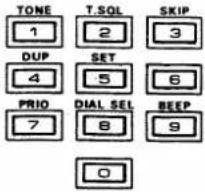 | Directly enter an operating frequency in VFO mode. (p. 15)Directly select a desired memory channel in MEMORY mode. (p. 22) |
[#](UP/SCAN)[*](DN/SCAN) KEYS  | Change VFO frequency in VFO mode. (p. 15)Push either key for more than 0.5sec. to start full band scan. (p. 26)Change the memory channel in MEMORY mode. (p. 21)Push either key for more than 0.5sec. to start memory scan. (p. 28) |
[A](CL·S.STOP) KEY | Selects VFO mode in MEMORY mode. (p. 14)Selects the previous mode in CALL CHANNEL mode. (p. 24)Stops scan and priority watch. (pgs. 26, 32)Clears KEYBOARD input in VFO mode. (p. 15) |
[B](MR) KEY | Selects MEMORY mode in VFO mode. (p. 20)Changes memory channel by 10 in MEMORY mode. (p. 22) |
[C](V/U) KEY | Selects either VHF or UHF band in VFO mode. (p. 14)Selects either VHF or UHF band in a memory channel programmed for full duplex. (p. 40) |
[D](CALL) KEY | Selects CALL CHANNEL mode in VFO or MEMORY mode. (p. 24)Selects previous mode in CALL CHANNEL mode. (p. 24) |
(2) SECONDARY FUNCTION
| KEY | DESCRIPTION |
| [FUNCTION] + [1] (TONE) | Turns the subaudible tone encoder ON and OFF (IC-32AT; or IC-32A/E with UT-40). (p. 19) |
| [FUNCTION] + [2] (T.SQL) | Turns ON and OFF optional tone squelch or pocket beep function (when UT-40 is installed). (p. 41) |
| [FUNCTION] + [3] (SKIP) | Programs a memory channel as a skip channel. (p. 30) |
| [FUNCTION] + [4] (DUP) | Selects -duplex, +duplex or simplex. (pgs. 18, 19) |
| [FUNCTION] + [5] (SET) | Selects SET mode in VFO mode. (p. 44) |
| [FUNCTION] + [7] (PRIO) | Starts the priority watch. (p. 31) |
| [FUNCTION] + [8] (DIAL SEL) | Selects a digit of dial select function in VFO mode. (pgs. 16, 20) |
| [FUNCTION] + [9] (BEEP) | Turns ON and OFF the beep tone function. (p. 42) |
| [FUNCTION] + [#] (UP/SCAN)[FUNCTION] + [*] (DN/SCAN) | Start a programmed scan in VFO mode. (p. 27)Start a selected band memory scan in MEMORY mode. (p. 29) |
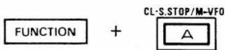
| [FUNCTION] + [A] (M▶VFO) | Transfers memory contents into VFO in ME-MORY mode. (p. 23)Transfers CALL channel contents into VFO in CALL CHANNEL mode. (p. 25) |
| [FUNCTION] + [B] (MW) | Writes the VFO contents in a memory channel in the VFO mode. (p. 23)Writes the VFO contents into the CALL channel in the CALL CHANNEL mode. (p. 25) |
| [FUNCTION] + [C] (SPLIT) | Selects or cancels full duplex operation in VFO mode or in the memory channel programmed for full duplex. (p. 38) |
| [FUNCTION] + [D] (LOCK) | Turns ON and OFF the lock function. (p. 42) |
5. PRE-OPERATION
5 - 1 CHARGING THE BATTERY PACK
(1) REMOVING THE BATTERY PACK
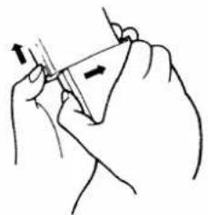
Push the [RELEASE] BUTTON upwards, and slide the battery pack to the right to remove it from the transceiver.
natural_image
Line drawing of a hand holding a triangular object with an arrow indicating direction (no text or symbols)(2) CHARGING CONNECTION
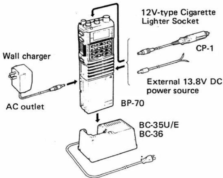
To charge the battery pack, use the supplied wall charger or an optional BC-35U/E or BC-36 AC BATTERY CHARGER, or other power source as shown below.
Connect an optional CP-1 CIGARETTE LIGHTER CABLE or external .12 \~ 15V DC power source to the [DC IN 13.8V] JACK for home or mobile operations. When the battery pack is attached, the battery pack will be charged automatically.
Charge the BP-70 for about 9hrs.; or the BP-3 for about 15hrs.
The EX-390 BOTTOM CAP is available from Icom for an external DC operation.
- Charging connection
NOTE: NEVER charge a battery pack from more than one power source.
text_image
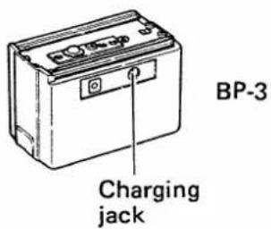
Wall charger AC outlet 12V-type Cigarette Lighter Socket CP-1 External 13.8V DC power source BP-70 BC-35U/E BC-36The BP-3 has a charger jack on the rear panel.
Use supplied wall charger, CP-1 (optional) or external 13.8V DC to this jack.
text_image
BP-3 Charging jackPRE-OPERATION 5.
(3) BATTERY PACK CAUTIONS
- NEVER throw the battery pack into a fire. Internal battery gas may cause an explosion.
- NEVER put the battery pack in water. If battery pack is wet, be sure to wipe it dry.
- NEVER short the terminals on the top panel of the battery pack. Use the plastic insulator strip provided to prevent this.
- Note that the [TX] INDICATOR may go out during HIGH output power operation with the BP-4. Because current drawn on the battery's internal resistance causes a voltage drop. In this state, the transceiver operates normally for a time. However, when the batteries are exhausted, exchange all old batteries for new ones. DO NOT use old batteries with new ones.
(4) BATTERY PACK LIFE
Stated operation times are approximate and conform to the following ratio:
Transmit : Receive : Standby 1min. 1min. 8min.
| VOLTAGE (V) | CAPACITY (mAh) | OPERATION TIME (hrs.) | ||
| VHF | UHF | |||
| BP-2 | 7.2 | 450 | 3.7 | 3.1 |
| BP-3 | 8.4 | 270 | 1.9 | 1.6 |
| BP-5 BP-5A | 10.8 | 450 | 3.2 | 2.4 |
| BP-7 | 13.2 | 450 | 3.4 | 2.4 |
| BP-8 | 8.4 | 800 | 5.8 | 4.8 |
| BP-70 | 13.2 | 270 | 2.0 | 1.5 |
(5) BATTERY PACK NOTE
The full charge capacity of NiCd batteries may be reduced if repeatedly charged with only partial discharge periods. This is called the Battery Memory Effect. If the battery capacity seems lower than when new, discharge the battery pack completely through normal use, then charge fully using the proper charger.
5. PRE-OPERATION
5 - 2 ANTENNA CONNECTION
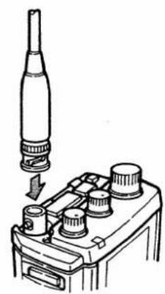
Insert the connector on the supplied antenna into the ANTENNA CONNECTOR on the top panel of the transceiver. Twist the connector clockwise.
natural_image
Diagram of a mechanical device with a cylindrical component inserted into a housing, showing internal components (no text or symbols)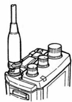
natural_image
Line drawing of a microscope with a pipette and three labeled components (no text or symbols)5 - 3 HANDSTRAP ATTACHMENT
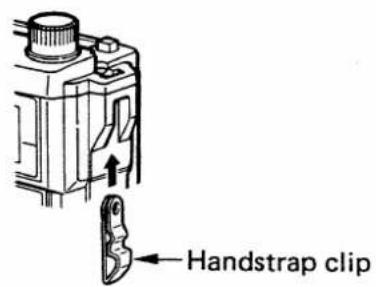
text_image
Handstrap clip1) Insert handstrap clip as shown in the diagram at left.
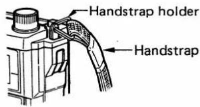
text_image
Handstrap holder Handstrap2) Slide the handstrap holder through the hole in the handstrap clip.
5 - 4 BELT CLIP ATTACHMENT

natural_image
Technical line drawing of a device housing with mounting holes and screw fasteners (no text or symbols)1) Remove the bushings from the two holes on the rear panel.
2) Attach the belt clip to the rear panel using the supplied screws and washers.
BASIC OPERATION 6.
6 - 1 FREQUENCY SETTINGS
Operating frequency can be set only in VFO mode.
(1) USING MAIN DIAL
1) Turn power ON.
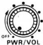
2) Select VFO mode.
1) Rotate the [PWR/VOL] CONTROL to turn the power ON.
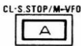
2) If "M" or "C" appears on the FUNCTION DISPLAY, push the A KEY to select VFO mode.
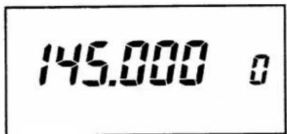
text_image
145.000 03) Push [C] (V/U).
3) Push the [C] (V/U) KEY to select VHF (144MHz) or UHF (430 or 440MHz) band.
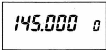
text_image
145.000 oVHF (144MHz) band
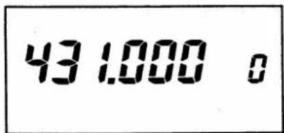
text_image
43 1.000 oUHF band
U.S.A. version : 440MHz band
Other versions : 430MHz band
4) Rotate MAIN DIAL.
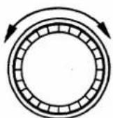
MAIN DIAL
4) Rotate the MAIN DIAL to change the operating frequency up or down.
- The MAIN DIAL changes the frequency in the programmed tuning step. See p. 45 for tuning step setting.
6. BASIC OPERATION
(2) USING [#] (UP) AND [\*] (DN) KEYS
1) Turn power ON and select VFO mode.
2) Push [#] (UP) or [*] (DN).
![ICOM IC-32AT - USING [#] (UP) AND [\*] (DN) KEYS - 1](/content/2026/05/777900/images/48d612bc6d508b0011d06e2a30c8ce8ca3d5bb76a8b55fd2b8f069692a75877d.jpg)
(3) USING DIGIT KEYS
1) Turn power ON and select VFO mode.
2) Push DIGIT KEYS.
| IC-32AT IC-32A | IC-32E | |
| 1 | - | 12.5 |
| 2 | - | 25.0 |
| 3 | - | 37.5 |
| 4 | - | - |
| 5 | 5 | 50.0 |
| 6 | - | 62.5 |
| 7 | - | 75.0 |
| 8 | - | 87.5 |
| 9 | - | - |
| 0 | 0 | 00.0 |
Unit : kHz
- The last used DIGIT KEY enters the frequency as shown in the table above.
- Note that “—” indicates the key entry can not be accepted, and previous operating frequency is recalled.
1) Turn the power ON and select VFO mode.
2) Push the [#] (UP) or [*] (DN) KEY to change the operating frequency.
- Either key changes the frequency in programmed tuning step.
- Either key is pushed more than 0.5sec. a full band scan starts.
1) Turn the power ON and select VFO mode.
2) Push the appropriate DIGIT KEYS for the desired operating frequency.
- Push four DIGIT KEYS representing the frequency desired.
| IC-32A/AT | Beginning with the 1MHz and ending with the 1kHz digit [5] or [0]. |
| IC-32E | Push three DIGIT KEYS beginning with the 1MHz digit and ending with the 10kHz digit. |
- If illegal digits or an out-of-band frequency have been entered, the entered ones are cancelled and the previous operating frequency will be recalled.
When a wrong key has been pushed, push the [A] (CL) KEY. The entered one are cancelled and the previous operating frequency will be recalled.
Example 1: When setting 448.75MHz (for IC-32A/AT U.S.A. versions).

text_image
DIAL SEL 8 PRIO 7 SET 5 0 448 8 → 4487 8 → 44875 8 → 448.750 8Decimal point disappears.
Decimal point appears.
Example 2: When setting 439.7125MHz (for IC-32E).
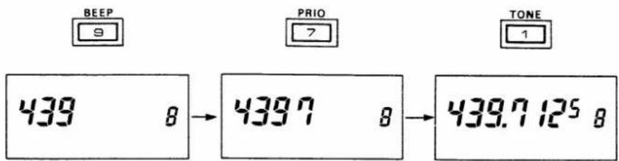
text_image
BEEP 9 PRIO 7 TONE 1 439 8 → 4397 8 → 439.7 125 8Decimal point disappears.
Decimal point appears.
(4) USING DIAL SELECT FUNCTION
1MHz or 100kHz digit can be changed with the MAIN DIAL. This function is convenient for changing frequency quickly.
1) Push [A] (CL).
1) Push the [A] (CL) KEY to select VFO mode.
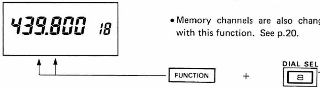
2) Push and hold [FUNCTION] and 8 until desired digit blinks.
2) Push and hold the [FUNCTION] SWITCH and then push the [8] (DIAL SEL) KEY several times until the 1MHz or 100kHz digit blinks.
- Once dial select function is set, the transceiver memorizes the function setting. Repeat steps 4 \~ 6 to change the 1MHz or 100kHz digit.
- Memory channels are also changed in VFO with this function. See p.20.
text_image
439.800 18 • Memory channels are also chang with this function. See p.20. FUNCTION + DIAL SEL 86. BASIC OPERATION
3) Release [8] (DIAL SEL) and [FUNCTION].
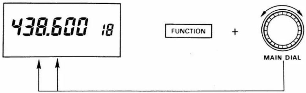
4) Push and hold [FUNCTION] and rotate MAIN DIAL.
3) Release the [8] (DIAL SEL) KEY and [FUNCTION] SWITCH.
4) Push and hold the [FUNCTION] SWITCH and then rotate the MAIN DIAL to select the 1MHz or 100kHz digit.
text_image
438.600 18 FUNCTION + MAIN DIAL6 - 2 RECEIVING
1) Turn power ON and adjust [PWR/VOL].
2) Adjust SQUELCH CONTROL.

3) Set operating frequency.
text_image
144.600 18 1 5 94) Push and hold [MONITOR].
MONITOR
1) Rotate the [PWR/VOL] CONTROL to turn the power ON and adjust a suitable audio level.
2) Adjust the [SQUELCH] CONTROL (IC-32A/AT) or the [SQL] CONTROL (IC-32E) until the noise is quieted.
3) Set the operating frequency. See Section 6 - 1 FREQUENCY SETTINGS.
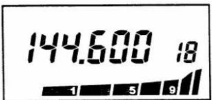
- When receiving a signal, the S/RF INDICATOR displays the signal strength and audio is emitted from the SPEAKER.
4) Push and hold the [MONITOR] SWITCH to open the squelch for monitoring the operating frequency.
- Also opens optional tone squelch (when UT-40 is installed).
6 - 3 TRANSMITTING
1) Turn power ON.
2) Select output power.

3) Select simplex mode.
text_image
FUNCTION + DUP 44) Push PTT SWITCH.
natural_image
Line drawing of a person holding a walkie-talkie (no text or symbols present)CAUTION: DO NOT transmit without an antenna or the transceiver may be damaged.
1) Rotate the [PWR/VOL] CONTROL to turn the power ON.
2) Push the [H/L] SWITCH on the top panel to select the desired output power.
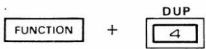
3) Select the simplex mode if "DUP", "—DUP" or "SPT" appears on the FUNCTION DISPLAY. Push and hold [FUNCTION] SWITCH and then push the [4] (DUP) or [C] (SPLIT) KEY.
4) Push the PTT SWITCH to begin transmitting, and speak into the MICROPHONE (located under the right side of the SPEAKER).
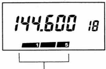
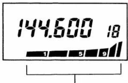
- The [TX] INDICATOR lights up and the S/RF INDICATOR bars indicate relative [H/L] SWITCH positions.
- When the battery is exhausted, the [TX] INDICATOR does not light up.
NOTE: DO NOT hold the transceiver too closely to your mouth or speak too loudly. This may distort the signal.
(LOW output power)
text_image
144.600 18 1 53 bars appear.
(HIGH output power)
text_image
144.600 18 1 5 9All bars appear.
6. BASIC OPERATION
6 - 4 REPEATER OPERATION
1) Set frequency.
2) Set semi duplex.
text_image
DUP 439.020 153) Push PTT SWITCH.
4) Push [MONITOR].
MONITOR
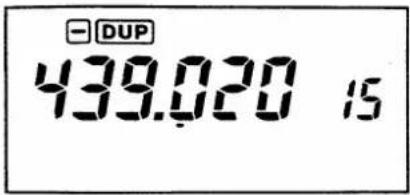
1) Set the desired receive frequency (repeater output frequency).
2) Push and hold the [FUNCTION] SWITCH and then push the [4] (DUP) KEY to select +semi duplex or -semi duplex operation.
- Refer to p. 45 for setting an offset frequency.
3) Push the PTT SWITCH to begin transmitting, and speak into the MICROPHONE.
- The transmit frequency automatically shifts with the programmed offset frequency.
4) Push the [MONITOR] SWITCH to monitor the transmit frequency (repeater input frequency), if needed.
• The squelch opens.
■ SOME CONTROLLED REPEATERS
text_image
FUNCTION + TONE 1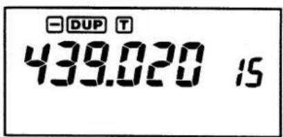
text_image
DUP T 439.020 15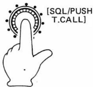
text_image
[SQL/PUSH T.CALL]• A repeater controlled by a subaudible tone. (with IC-32AT)
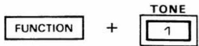
Push and hold the [FUNCTION] SWITCH and then push the 1 KEY to turn the subaudible tone encoder ON. See p. 44 for setting a subaudible tone frequency.
- A repeater controlled by DTMF signals. (with IC-32AT)
Push and hold the PTT SWITCH and then push the required keys on the KEYBOARD.
- A repeater controlled by a 1750Hz tone call signal. (with IC-32E)
Push and hold the [SQL] CONTROL for approximately 1 \~ 3sec.
MEMORY AND CALL OPERATIONS /.
7.
7 - 1 MEMORY CHANNEL SELECTION
20 memory channels store operating frequencies and other information.
Each memory channel has double space, one for operating frequency and the other for full duplex frequency or offset frequency. If you program only simplex frequency, you can use 40 memory channels. See p. 40.
(1) USING MAIN DIAL
1) Push [B] (MR).
text_image
MR/MW B 144.860 72) Rotate MAIN DIAL.
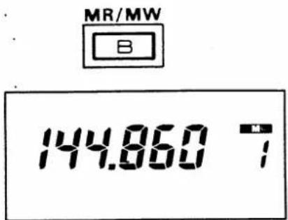
1) Push the B KEY to select MEMORY mode.
- If "C" already appears on the FUNCTION DISPLAY, push the [A] (CL) KEY fast.
text_image
433.280 Ω MAIN DIAL(2) USING DIAL SELECT FUNCTION
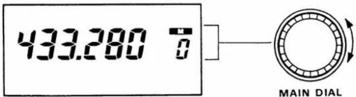
2) Rotate the MAIN DIAL to select the memory channel.
Memory channel can be changed with the MAIN DIAL in VFO mode. This function is convenient for memory writing.
1) Push [A] (CL).
2) Push and hold [FUNCTION] and [8] (DIAL SEL) until memory channel blinks.
1) Push the [A] (CL) KEY to select VFO mode.
2) Push and hold the [FUNCTION] SWITCH and then push the 8 KEY several times the memory channel number blinks.

text_image
439.800 18 FUNCTION + DIAL SEL 87. MEMORY AND CALL OPERATIONS
3) Release [8] (DIAL SEL) and [FUNCTION].
3) Release the [8] (DIAL SEL) KEY and [FUNCTION] SWITCH.
Once dial select function is set, the transceiver memorizes the function setting. Repeat steps 4 \~ 6 below to change the memory channel number.
4) Push [A] (CL).
4) Push the [A] (CL) KEY to select VFO mode.
5) Push and hold [FUNCTION] and rotate MAIN DIAL.
5) Push and hold the [FUNCTION] SWITCH and then rotate the MAIN DIAL to select the memory channel number.

text_image
433.560 10 FUNCTION + MAIN DIAL6) Release [FUNCTION].
6) Release the [FUNCTION] SWITCH.
(3) USING [#] (UP) AND [*] (DN) KEYS
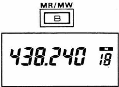
1) Push [B] (MR).
1) Push the B KEY to select MEMORY mode.
text_image
MR/MW B 438.240 M 182) Push [#] (UP) or [*] (DN).
2) Push the [#] (UP) or [*] (DN) KEY to select memory channel up or down.
or

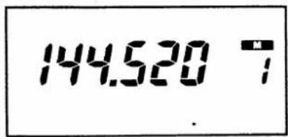
text_image
144.520 7- Note that if pushed and hold either key approximately 0.5sec., memory scan starts. See p. 28.
MEMORY AND CALL OPERATIONS 7.
(4) USING DIGIT KEYS
1) Push [B] (MR).
2) Push DIGIT KEYS.
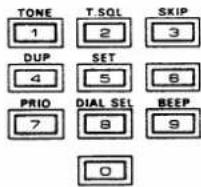
1) Push the B KEY to select MEMORY mode.
2) Push DIGIT KEYS to select the desired memory channel.
- If the displayed memory channel differs from the desired memory channel by 10, push the [B] (MR) KEY to switch the desired memory channel.
Example 3: When selecting memory channel 8.

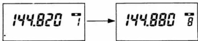
text_image
144.820 7 → 144.880 8- If memory channel 18 is displayed, push the B KEY to switch to memory channel 8.
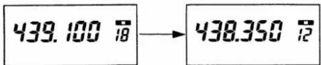
Example 4: When selecting memory channel 12.

text_image
439.100 18 → 438.350 12- If memory channel 2 is displayed, push the [B] (MR) KEY to switch to memory channel 12.
7. MEMORY AND CALL OPERATIONS
7 - 2 MEMORY WRITING
1) Select memory channel.
text_image
433.000 112) Push [A] (CL).
3) Select VFO contents.
text_image
439.680 114) Push and hold [FUNCTION] and then push B.
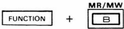
Memorize information into memory channels as described below. See p. 39 for full duplex information writing.
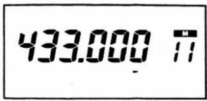
1) Select the desired memory channel. See Section 7-1 MEMORY CHANNEL SELECTION.
- The dial select function can be used to change the memory channel number in VFO mode. See p. 20.
2) Push the [A] (CL) KEY to select VFO mode.
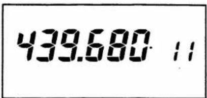
3) Select contents such as frequency, repeater information, etc.
4) Push and hold the [FUNCTION] SWITCH and then push the [B] (MW) KEY until 3 beep tone are emitted in VFO mode.
- Memory writing completed. To check contents, push the [B] (MR) KEY.
7 - 3 MEMORY TRANSFERRING
1) Select memory channel.
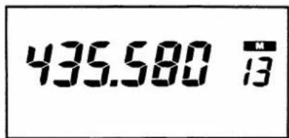
text_image
435.580 13Copy and transfer the displayed memory contents into VFO mode. This function is useful for searching for signals around the memory channel frequency.
1) Select the required memory channel.
• See Section 7-1 MEMORY CHANNEL SELECTION.
MEMORY AND CALL OPERATIONS 7.
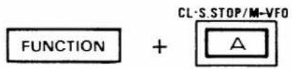
2) Push and hold [FUNCTION] and then push [A] (M▶VFO).
text_image
FUNCTION + CL-S.STOP/M-VFO A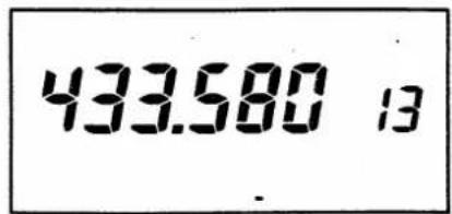
text_image
433.580 132) Push and hold the [FUNCTION] SWITCH and then push the [A] (M▶VFO) KEY until 3 beep tones are emitted in MEMORY mode.
- Displayed memory contents are transferred to the VFO.
- The transceiver is changed to VFO mode.
7 - 4 CALL CHANNEL OPERATION
(1) CALL CHANNEL READING
1) Push A.
2) Push [C] (V/U).
3) Push [D] (CALL).
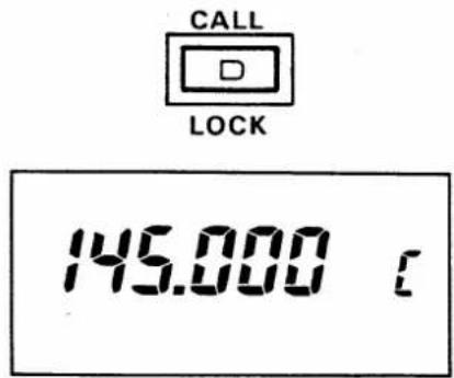
text_image
CALL LOCK 145.000 €(2) CALL CHANNELS PROGRAMMING
Your highest priority channels can be easily called from programmed call channels.
1) Push the [A] (CL) KEY to select VFO mode.
2) Push the [C] (V/U) KEY to select VHF or UHF band.
3) Push the [D] (CALL) KEY to select or cancel the CALL channel.
- "C" appears in MEMORY CHANNEL INDICATOR.
- The [A] (CL) KEY also cancels the CALL channel.
Note that CALL channels can not be stored full duplex information.
The transceiver has two call channels. One is for VHF band, and another for UHF band. Set each CALL channel separately.
1) Push [A] (CE).
1) Push the [A] (CL) KEY to select VFO mode.
7. MEMORY AND CALL OPERATIONS
2) Push [C] (V/U).
3) Select VFO contents.
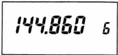
text_image
144.860 64) Push [D] (CALL).
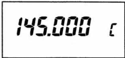
text_image
145.000 c5) Push and hold [FUNCTION] and then push [B] (MW).
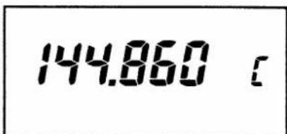
text_image
144.860 c(3) CALL CHANNEL TRANSFERRING
1) Select CALL channel.
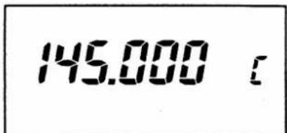
text_image
145.000 [2) Push and hold [FUNCTION] and then push [A] (M ▶ VFO).
text_image
FUNCTION + CL-S.STOP/M-VFO A2) Push the [C] (V/U) KEY to select VHF or UHF band.
3) Select contents such as frequency, repeater information, etc., you wish to write into the CALL channel.
4) Push the D KEY to select CALL channel.
5) Push and hold the [FUNCTION] SWITCH and then push the [B] (MW) KEY until 3 beep tones are emitted from the transceiver.
- The desired contents are now programmed.
This function allows you to use CALL channel contents to use in VFO mode.
1) Select the required CALL channel. See (1) CALL CHANNEL READING.
2) Push and hold the [FUNCTION] SWITCH and then push the [A] (M▶VFO) KEY until 3 beep tones are emitted from the transceiver.
- Displayed CALL channel contents are transferred to a VFO.
- The transceiver is changed to VFO mode.
SCAN AND WATCH OPERATIONS 8.
8 - 1 FULL BAND SCAN
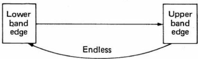
Full band scan repeatedly scans between upper and lower edges of VHF or UHF band.
• Full band scan operation
flowchart
graph LR
    A["Lower band edge"] --> B["Upper band edge"]
    B -->|Endless| A
1) Push [A] (CL).
2) Push [C] (V/U).
3) Adjust SQUELCH CONTROL.

4) Push and hold [#] (UP/SCAN) or [*] (DN/SCAN).
or
text_image
144680 ;1) Push the [A] (CL) KEY to select VFO mode.
2) Push the [C] (V/U) KEY to select the desired band.
3) Adjust the SQUELCH CONTROL to the squelch threshold point.
4) Push and hold the [#] (UP/SCAN) or [*] (DN/SCAN) KEY approximately 0.5sec. to start full band scan.
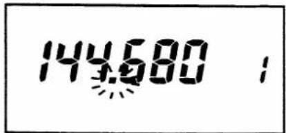
- The decimal point blinks while the scan is operating. (See the diagram at left.)
- The scan pauses when the transceiver receives a signal.
- The scan then resumes 15sec. after a signal receives; or 2sec. after a signal disappears.
- The scan does not pause when the [#] (UP/SCAN) or [*] (DN/SCAN) KEY is pushed and held.
5) Push [A] (S.STOP) to stop scan.
5) Push the [A] (S.STOP) KEY to stop the scan.
- The [#] (UP/SCAN), [*] (DN/SCAN) KEY or also MAIN DIAL stops the scan.
8. SCAN AND WATCH OPERATIONS
8 - 2 PROGRAMMED SCAN
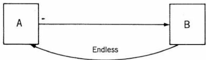
Programmed scan repeatedly scans between user-programmed independent frequency edges to monitor a particular section of the band. See p. 46 for setting scan edges.
- Programmed scan operation
flowchart
graph LR
    A["A"] -->|Endless| B["B"]
    B --> A
NOTE: The upper scan edge may be programmed into A or B.
1) Push [A] (CL).
1) Push the [A] (CL) KEY to select VFO mode.
2) Push [C] (V/U) to select band.
2) Push the [C] (V/U) KEY to select desired band.
3) Adjust SQUELCH CONTROL.
3) Adjust the SQUELCH CONTROL to the squelch threshold point.

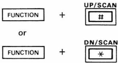
4) Push and hold [FUNCTION] and then push [#] (UP/SCAN) or [*] (DN/SCAN).
4) Push and hold the [FUNCTION] SWITCH and then push the [#] (UP/SCAN) or [*] (DN/SCAN) KEY to start the programmed scan.
text_image
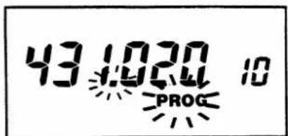
FUNCTION + UP/SCAN # or FUNCTION + DN/SCAN *- The decimal point and "PROG" blink while the scan is operating.
- This scan pauses, resumes and stops like a full band scan. See Section 8 - 1 FULL BAND SCAN.
text_image
43:02:00 10 PROGSCAN AND WATCH OPERATIONS 8.
8 - 3 MEMORY SCAN
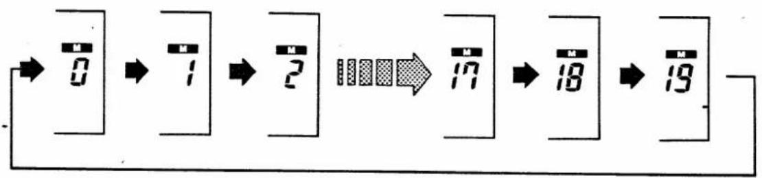
Memory scan automatically scans programmed memory channels except skip channels described in Section 8 - 5 SKIP FUNCTION.
flowchart
graph LR
    A["0"] --> B["1"]
    B --> C["2"]
    C --> D["17"]
    D --> E["18"]
    E --> F["19"]
1) Push [B] (MR).
2) Adjust SQUELCH CONTROL.

3) Push and hold [#] (UP/SCAN) or [*] (DN/SCAN).
or
1) Push the B KEY to select MEMORY mode.
- If "C" already appears on the FUNCTION DISPLAY, push the [A] (CL) KEY fast.
2) Adjust the SQUELCH CONTROL to the squelch threshold point.
3) Push and hold the [#] (UP/SCAN) or [*] (DN/SCAN) KEY approximately 0.5sec. to start the memory scan.
- The decimal point and "M" blink while the scan is operating.
- This scan pauses, resumes and stops like a full band scan. See Section 8 - 1 FULL BAND SCAN.
8. SCAN AND WATCH OPERATIONS
8 - 4 SELECTED BAND MEMORY SCAN
Selected band memory scan automatically scans programmed memory channels with the same band except the skip channels described in Section 8 - 5 SKIP FUNCTION.
- Selected band memory scan simulation
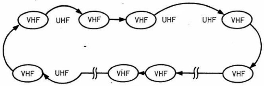
flowchart
graph TD
    A["VHF"] -->|UHF| B["VHF"]
    B --> C["VHF"]
    C -->|UHF| D["VHF"]
    D --> E["VHF"]
    E --> F["VHF"]
    F --> G["VHF"]
    G --> H["VHF"]
    H --> I["VHF"]
    I --> J["VHF"]
    J --> K["VHF"]
    K --> L["VHF"]
    L --> M["VHF"]
    M --> N["VHF"]
    N --> O["VHF"]
    O --> P["VHF"]
    P --> Q["VHF"]
    Q --> R["VHF"]
    R --> S["VHF"]
    S --> T["VHF"]
    T --> U["VHF"]
    U --> V["VHF"]
    V --> W["VHF"]
    W --> X["VHF"]
    X --> Y["VHF"]
    Y --> Z["VHF"]
    Z --> A
1) Push [A] (CL).
2) Push B.
3) Select the memory channel on your desired band to be scan.
4) Adjust SQUELCH CONTROL.

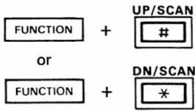
5) Push and hold [FUNCTION] and then push [#] (UP/SCAN) or [*] (DN/SCAN).
text_image
FUNCTION + UP/SCANor
FUNCTION + DN/SCAN *1) Push the [A] (CL) KEY to select VFO mode.
2) Push the B KEY to select MEMORY mode.
3) Select the memory channel on your desired band to be scan. See p. 20.
4) Adjust the SQUELCH CONTROL to the squelch threshold point.
5) Push and hold the [FUNCTION] SWITCH and then push the # or * KEY.
- The decimal point and "M" blink while the scan is operating.
- This scan pauses, resumes and stops like a full band scan. See Section 8 - 1 FULL BAND SCAN.
SCAN AND WATCH OPERATIONS 8.
8 - 5 SKIP FUNCTION
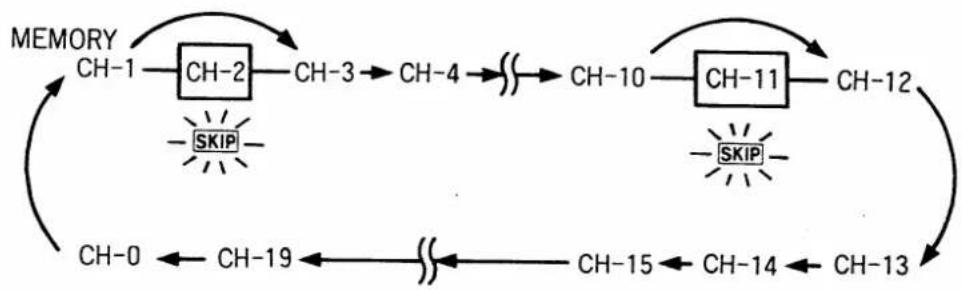
An unrequired memory channel can be skipped during memory scan and selected band memory scan. This section explains how to program a skip channel.
- Skip function simulation
flowchart
graph TD
    A["CH-1"] --> B["CH-2"]
    B --> C["CH-3"]
    C --> D["CH-4"]
    D --> E["..."]
    E --> F["CH-10"]
    F --> G["CH-11"]
    G --> H["CH-12"]
    H --> I["..."]
    I --> J["CH-13"]
    J --> K["CH-14"]
    K --> L["CH-15"]
    L --> M["..."]
    M --> N["CH-19"]
    N --> O["..."]
    O --> P["CH-0"]
    P --> Q["..."]
    Q --> R["..."]
    R --> S["..."]
    S --> T["..."]
    T --> U["..."]
    U --> V["..."]
    V --> W["..."]
    W --> X["..."]
    X --> Y["..."]
    Y --> Z["..."]
    Z --> A
    style A fill:#f9f,stroke:#333
    style B fill:#f9f,stroke:#333
    style C fill:#f9f,stroke:#333
    style D fill:#f9f,stroke:#333
    style E fill:#f9f,stroke:#333
    style F fill:#f9f,stroke:#333
    style G fill:#f9f,stroke:#333
    style H fill:#f9f,stroke:#333
    style I fill:#f9f,stroke:#333
    style J fill:#f9f,stroke:#333
    style K fill:#f9f,stroke:#333
    style L fill:#f9f,stroke:#333
    style M fill:#f9f,stroke:#333
    style N fill:#f9f,stroke:#333
    style O fill:#f9f,stroke:#333
    style P fill:#f9f,stroke:#333
    style Q fill:#f9f,stroke:#333
    style R fill:#f9f,stroke:#333
    style S fill:#f9f,stroke:#333
    style T fill:#f9f,stroke:#333
    style U fill:#f9f,stroke:#333
    style V fill:#f9f,stroke:#333
1) Push B.
2) Select memory channel.
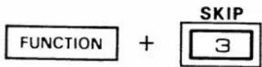
3) Push and hold [FUNCTION] and then push [3] (SKIP).
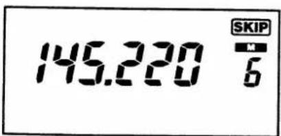
text_image
145.220 SKIP M 61) Push the B KEY to select MEMORY mode.
- If "C" already appears on the FUNCTION DISPLAY, push the [A] (CL) KEY first.
2) Select memory channel you wish to program as a skip channel. See p. 20.
3) Push and hold the [FUNCTION] SWITCH and then push the [3] (SKIP) KEY to program and cancel the skip function.
- "SKIP" appears when the memory channel is programmed as a skip channel.
8. SCAN AND WATCH OPERATIONS
8 - 6 PRIORITY WATCH
The transceiver watches a priority channel during VFO operation with 5sec. when the priority watch is operating.
Note that the pocket beep function cannot be used during priority watch.
(1) VFO AND SPECIFIED MEMORY CHANNEL
1) Push [B] (MR).
2) Select memory channel.
3) Push and hold [FUNCTION] and then push [7] (PRIO).
1) Push the B KEY to select MEMORY mode.
- If "C" already appears on the FUNCTION DISPLAY, push the [A] (CL) KEY fast.
2) Select the desired memory channel. See p. 20.
3) Push and hold the [FUNCTION] SWITCH and then push the [7] (PRIO) KEY.
- "PRIO" appears on the FUNCTION DISPLAY.
- During priority watch, the display frequency can be changed with the MAIN DIAL, [#] (UP), [*] (DN) or DIGIT KEYS on the KEYBOARD.
- The transceiver receives the following frequencies:
The VFO frequency: approx. 5sec.
The specified memory channel: approx. 250msec.
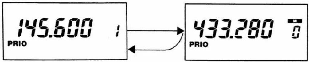
text_image
145.600 PRIO 433.280 T PRIOSCAN AND WATCH OPERATIONS 8.
4) When a signal is received on the memory channel.
text_image
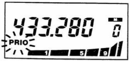
433.280 PRIO 1 5 94) "PRIO" blinks when the transceiver receives a signal on the specified memory channel frequency.
- Push the [A] (S.STOP) KEY to return to VFO frequency. The priority watch continues.
- The priority watch then resumes 15sec. after receiving a signal or 2sec. after signal disappears.
- The watch function continues even when the transceiver receives a signal on the VFO frequency.
- By pushing the PTT SWITCH, transmission on the VFO frequency is possible without stopping the priority watch.
5) Push [A] (S. STOP) to stop the function.
5) Push the [A] (S. STOP) KEY to stop the function.
• The transceiver becomes VFO mode.
(2) VFO AND ANOTHER BAND VFO
1) Push [A] (CL).
1) Push the [A] (CL) KEY to select VFO mode.
2) Set VFO frequency.
text_image
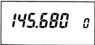
145.680 o2) Set a VFO frequency. See p. 14.
3) Push [C] (V/U).
3) Push the [C] (V/U) KEY to select another band.
8. SCAN AND WATCH OPERATIONS
4) Set another band VFO frequency.
text_image
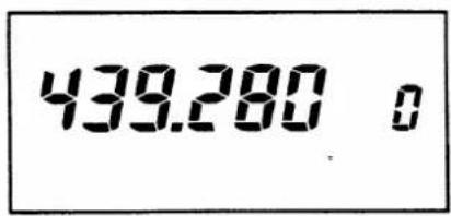
439.280 o4) Set another band VFO frequency. Then push the C KEY again to return to the previously selected VFO.
5) Push and hold [FUNCTION] and then push [7] (PRIO).
text_image
FUNCTION + PRIO 75) Push and hold the [FUNCTION] SWITCH and then push the [7] (PRIO) KEY.
- "PRIO" appears on the FUNCTION DISPLAY.
- "PRIO" blinks when the transceiver receives a signal on VFO frequency of another band.
- See step 4 in (1) VFO AND SPECIFIED MEMORY CHANNEL.
• The transceiver receives the following frequencies:
The VFO frequency: approx. 5sec.
Another band VFO frequency: approx. 250msec.

text_image
145.680 0 PRIO 439.280 0 PRIO6) Push A to stop function.
6) Push the [A] (S.STOP) KEY while "PRIO" does not blink to stop the function.
- The transceiver receives the displayed VFO frequency.
- Push the [C] (V/U) KEY to select another band VFO.
SCAN AND WATCH OPERATIONS 8.
(3) VFO AND CALL CHANNEL
1) Push [D] (CALL).
2) Push and hold [FUNCTION] and then push [7] (PRIO).
1) Push the D KEY to select a CALL CHANNEL on your desired band.
2) Push and hold the [FUNCTION] SWITCH and then push the [7] (PRIO) KEY.
- "PRIO" appears on the FUNCTION DISPLAY.
- "PRIO" blinks when the transceiver receives a signal on the CALL channel frequency.
• See step 4 in (1) VFO AND SPECIFIED MEMORY CHANNEL.
- The transceiver receives the following frequencies:
The VFO frequency: approx. 5sec.
CALL channel: approx. 250msec.

text_image
145.680 0 PRIO 145.000 € PRIO3) Push A to stop function.
3) Push the [A] (S.STOP) KEY while "PRIO" does not blink to stop the function.
- The transceiver is changed to VFO mode.
- Push the [D] (CALL) KEY to select CALL channel.
8. SCAN AND WATCH OPERATIONS
(4) VFO AND MEMORY CHANNELS
1) Push [B] (MR).
2) Start memory scan or selected band memory scan.
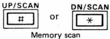
text_image
UP/SCAN # or DN/SCAN * Memory scanSelected band memory scan
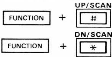
text_image
FUNCTION + UP/SCAN # FUNCTION + DN/SCAN *3) Push and hold [FUNCTION] and then push [7] (PRIO).

1) Push the B KEY to select MEMORY mode.
- If "C" already appears on the FUNCTION DISPLAY, push the [A] (CL) KEY fast.
2) Start the memory scan or selected band memory scan as follows.
- Push the [#] (UP/SCAN) or [*] (DN/SCAN) KEY approximately 0.5sec. to start the memory scan.
- Push and hold the [FUNCTION] SWITCH and then push the # or * KEY to start selected band memory scan.
3) Push and hold the [FUNCTION] SWITCH and then push the [7] (PRIO) KEY.
- "PRIO" appears on the FUNCTION DISPLAY.
- The skip function is useful for skipping unnecessary memory channel.
- "PRIO" blinks when the transceiver receives a signal on a memory channel frequency.
- See step 4 in (1) VFO ANE SPECIFIED MEMORY CHANNEL.
SCAN AND WATCH OPERATIONS 8.
The transceiver receives the following frequencies during watch operation using VFO and memory channels:
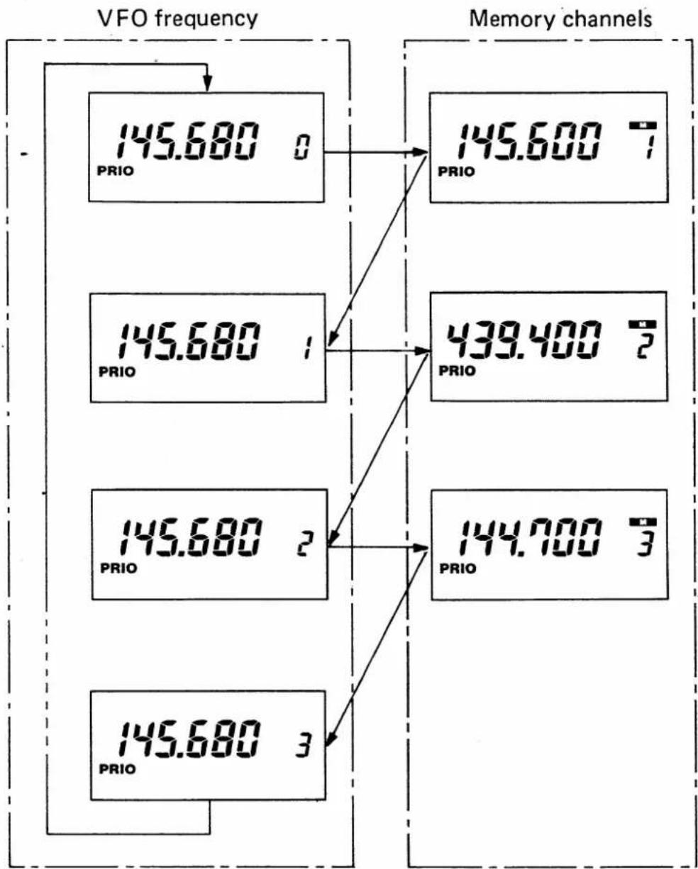
other
| VFO frequency | Memory channels | PRIO | | ------------- | --------------- | ---- | | 0 | PRIO | 145.680 | | 1 | PRIO | 145.680 | | 2 | PRIO | 145.680 | | 3 | PRIO | 145.680 |Each memory channel is watched for approx. 250msec. at approx. 5sec. intervals.
4) Push [A] (S.STOP) to stop function.
4) Push the A KEY while "PRIO" does not blink to stop the function.
• The transceiver becomes VFO mode.
- Push the B KEY to select MEMORY mode.
9. SPECIAL FUNCTIONS
9 - 1 FULL DUPLEX OPERATION
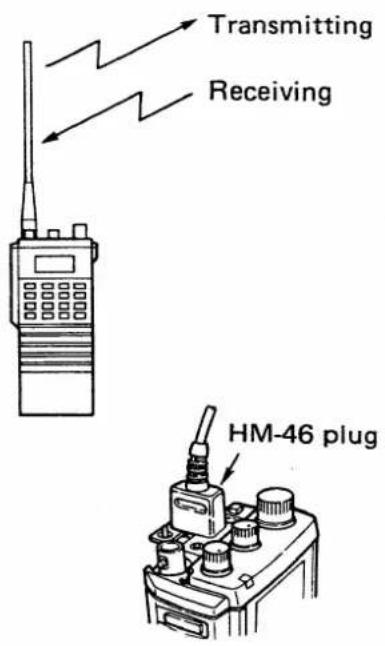
text_image
Transmitting Receiving HM-46 plug(1) FULL DUPLEX OPERATION USING VFOS
1) Push [A] (CL).
2) Set VFO frequency.
text_image
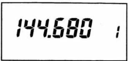
144.680 ;3) Push [C] (V/U).
4) Set another band VFO frequency.
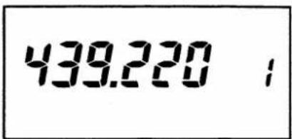
text_image
439.220 ;Full duplex means simulataneously transmitting on one band and receiving on another band.
NOTE: To prevent howling, AVOID setting the UHF band frequency near to the third multiple of the VHF band frequency.
We recommend using the supplied earphone during full duplex operation.
When using the optional HM-46 SPEAKER-MICROPHONE, connect only the microphone plug to the [MIC] JACK on the top panel. See the diagram at left.
The optional HS-10 HEADSET cannot be used during full duplex operation.
The VFOs can be used for full duplex operation.
1) Push the [A] (CL) KEY to select VFO mode.
2) Set VFO frequency. See p. 14.
3) Push the [C] (V/U) KEY to change to another band.
4) Set another band VFO frequency.
SPECIAL FUNCTIONS 9.
5) Push [C] (V/U) to select receive band.
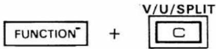
6) Push and hold [FUNCTION] and then push [C] (SPLIT).
text_image
FUNCTION⁻ + V/U/SPLIT C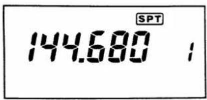
text_image
144.680 SPT7) Push PTT SWITCH.
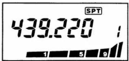
text_image
SPT 439.220 ; 1 5 98) Push and hold [FUNCTION] and then C to cancel full duplex operation.
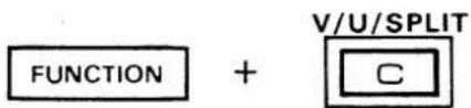
text_image
FUNCTION + V/U/SPLIT C5) Push the [C] (V/U) KEY to select receive band.
6) Push and hold the [FUNCTION] SWITCH and then push the [C] (SPLIT) KEY.
- "SPT" appears on the FUNCTION DISPLAY.
- The FUNCTION DISPLAY indicates receive frequency.
- Transmit frequency can be received while the [MONITOR] SWITCH is pushed.
- Push and hold the [MONITOR] SWITCH and then rotate the MAIN DIAL or push the [#] (UP) or * KEY to change transmit frequency.
7) Push the PTT SWITCH to begin transmission on transmit frequency.
- Transmit frequency appears on the FUNCTION DISPLAY during transmission.
- The transceiver simultaneously receives on receive frequency.
8) Push and hold the [FUNCTION] SWITCH and then push the [C] (SPLIT) KEY to cancel full duplex operation.
9. SPECIAL FUNCTIONS
(2) FULL DUPLEX INFORMATION WRITING
Each of the 20 memory channels can store one transmit frequency and one receive frequency for full duplex operation. Memorize full duplex information as described below.
1) Select memory channel.
1) Select the desired memory channel to be programmed.
2) Set VFO frequencies.
2) Set VFO frequencies for full duplex operation. See steps 1 \~ 6 in (1) FULL DUPLEX OPERATION USING VFOS.
3) Push and hold [FUNCTION] and then [B] (MW).
3) Push and hold the [FUNCTION] SWITCH and then push the [B] (MW) KEY until 3 beep tones are emitted from the transceiver.

• Full duplex information is memorized.
(3) FULL DUPLEX OPERATION USING MEMORY CHANNEL
Use memory channels for full duplex operation as described below.
1) Push [B] (MR).
1) Push the B KEY to select MEMORY mode.
2) Select memory channel.
2) Select the desired memory channel programmed for full duplex. See p. 20.
3) Push [C] (V/U) to select receive band.
3) Push the [C] (V/U) KEY to select receive band.
4) Push PTT SWITCH.
4) Operate in the same manner described steps 7 and 8 in (1) FULL DUPLEX OPERATION USING VFOS.
SPECIAL FUNCTIONS 9.
(4) MEMORY EXPANSION FUNCTION
1) Write full duplex information into memory channel.
2) Push [B] (MR).
3) Select memory channel.
4) Push and hold [FUNCTION] and then push [C] (SPLIT).
5) Push [C] (V/U) to select operating band.
6) Push PTT SWITCH.
Each memory channel memorizes one VHF and one UHF band frequencies instead of offset frequency. Total of 20 VHF and 20 UHF simplex frequencies can be memorize in the IC-32A/AT/E.
1) Write both VHF and UHF bands information as described in (2) FULL DUPLEX INFORMATION WRITING.
2) Push the B KEY to select MEMORY mode.
3) Select the desired memory channel programmed for full duplex. See p. 20.
4) Push and hold the [FUNCTION] SWITCH and then push the [C] (SPLIT) KEY.
- "SPT" disappears from the FUNCTION DISPLAY.
- The memory channel still contains full duplex information.
5) Push the [C] (V/U) KEY to select the operating band.
6) The transceiver transmits on the displayed frequency.
9. SPECIAL FUNCTIONS
9-2 POCKET BEEP AND TONE SQUELCH FUNCTIONS
1) Push and hold [FUNCTION] and then push [2] (T.SQL).
text_image
FUNCTION + T.SQL 22) When the correct tone signal is received.
Pocket beep function
text_image
SQL 432.240 14 (••) 1 5 9 BEEP BEEP BEEPTone squelch function
text_image
Only same tone is received.3) When the incorrect tone signal is received.
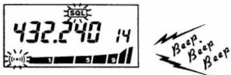
These functions require an optional UT-40 TONE SQUELCH UNIT. Note that these functions can be used with the IC-32A/AT/E.
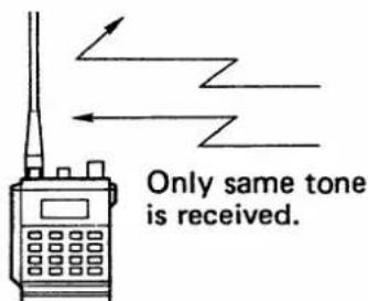
1) Push and hold the [FUNCTION] SWITCH and then push the [2] (T.SQL) KEY to sequentially turn the tone squelch and pocket beep functions ON and OFF.
- SQL : Pocket beep function T SQL : Tone squelch function
2) When the signal included correct tone is received:
While the pocket beep function is selected, beep tones emit over the speaker for 30sec. and "SQL" and "((·)))" flash on the FUNCTION DISPLAY.
- To stop the beep within 30sec., push the [A] (CL) KEY or the PTT SWITCH. The transceiver selects the tone squelch function.
While the tone squelch function is selected, received audio emits over the speaker.
3) When the signal included incorrect tone is received, the S/RF INDICATOR shows the relative signal strength. However, the squelch does not open.
- To listen the receiving signal, push the [MONITOR] SWITCH.
SPECIAL FUNCTIONS 9.
9 - 3 BEEP TONE FUNCTION
text_image
FUNCTION + BEEP 9
text_image
BeepA beep tone is emitted each time a key is pushed. If you do not require beep tones, they can be eliminated in the following way:
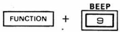
Push and hold the [FUNCTION] SWITCH and then push the [9] (BEEP) KEY to turn the beep tone function ON and OFF.
When this function is ON the transceiver emits following tones:
- A high tone is emitted when a function is operational.
- A low tone is emitted when a function is not operational.
• Three high tones are emitted when:
- Memory writing
- Memory transferring
- CALL channel writing
- CALL channel transferring
- The pocket beep function is activated even if the beep tone function is turned OFF.
9 - 4 LOCK FUNCTION
text_image
FUNCTION + CALL □ LOCK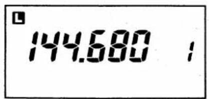
text_image
144.680 ;This function prevents accidental changes of the frequency or other setting.
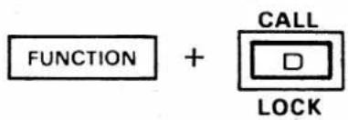
Push and hold the [FUNCTION] SWITCH and then push the [D] (LOCK) KEY to turn the lock function ON and OFF.
- "L" appears when the lock function is activated.
10. SET MODE
10 - 1 SET MODE CONSTRUCTION
The transceiver has a convenient SET mode for programming:
- Subaudible tone frequencies
- Offset frequencies
- Tuning steps
- Scan edges
- Power saver ON/OFF
(1) FLOW CHART OF SET MODE
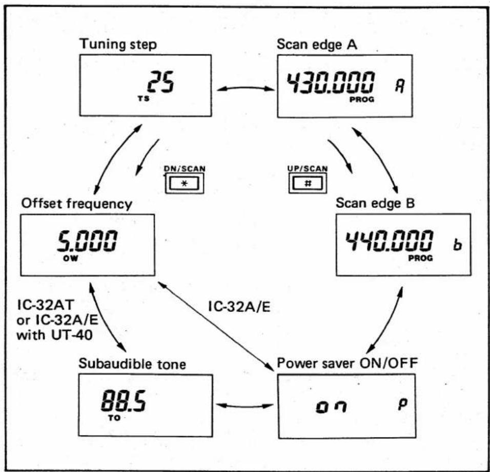
flowchart
graph TD
    A["Tuning step 25 TS"] --> B["Scan edge A 430.000 PROG R"]
    B --> C["Scan edge B 440.000 PROG b"]
    C --> D["Power saver ON/OFF on P"]
    D --> E["Subaudible tone 88.5 TO"]
    E --> F["Offset frequency 5.000 ow"]
    F --> G["DN/SCAN *"]
    G --> A
    C --> H["UP/SCAN #"]
    H --> B
    D --> I["IC-32A/E"]
    I --> E
    E --> J["IC-32AT or IC-32A/E with UT-40"]

text_image
CL-S.STOP/M-VFO A FUNCTION + SET 5 433.000 11 VFO modeSET MODE 10.
(2) SET MODE SELECTION
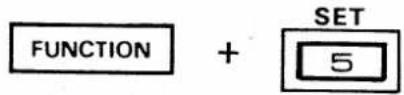
1) Push the [A] (CL) KEY to select VFO mode.
2) Push the [C] (V/U) KEY to select VHF or UHF band.
3) Push and hold the [FUNCTION] SWITCH and then push the [5] (SET) KEY while in VFO mode.
The transceiver starts again in the place in the cycle where it last stopped.
NOTE: Set each parameter for VHF and UHF band separately (except the power saver ON/OFF).
10 - 2 SUBAUDIBLE TONE
text_image
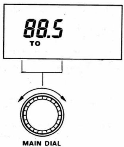
88.5 TO MAIN DIALThe display shows that the subaudible tone frequency has been set at 88.5Hz.
One of 38 different subaudible tone encoder frequency can be programmed to access a repeater or 37 different tone encoder/decoder frequencies (when an optional UT-40 TONE SQUELCH UNIT is installed).
The IC-32A/E can be programmed only when the UT-40 is installed.
1) Push the [A] (CL) KEY to select VFO mode.
2) Push and hold the [FUNCTION] SWITCH and then push the [5] (SET) KEY to select SET mode.
3) Push the [#] (UP) or [*] (DN) KEY several times until "TO" blinks on the FUNCTION DISPLAY.
4) Rotate the MAIN DIAL to select a desired subaudible tone frequency.
5) Push the [A] (CL) KEY to return to VFO mode, or push the [#] (UP) or [*] (DN) KEY to program the next parameter.
10. SET MODE
10 - 3 OFFSET FREQUENCY
text_image
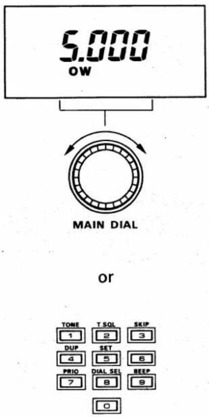
5.000 OW MAIN DIAL or TONE T SQL SKIP 1 2 3 DUP SET 4 5 6 PRIO DIAL SEL BEEP 7 8 9 0When + or —semi duplex operation is selected, the transmit frequency is lower or higher than the receive frequency with this offset.
1) Push the [A] (CL) KEY to select VFO mode.
2) Push and hold the [FUNCTION] SWITCH and then push the [5] (SET) KEY to select SET mode.
3) Push the # or * KEY several times until "OW" blinks on the FUNCTION DISPLAY.
4) Select the offset frequency using the MAIN DIAL, or DIGIT KEYS in the same manner as selecting an operating frequency. See p. 14.
- Using the MAIN DIAL with the [FUNCTION] SWITCH changes 100kHz digit.
5) Push the [A] (CL) KEY to return to VFO mode, or push the [#] (UP) or [*] (DN) KEY to program the next parameter.
10 - 4 TUNING STEP
text_image
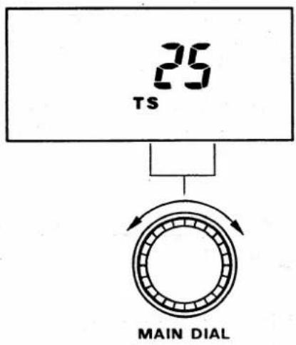
25 TS MAIN DIALWhen the [#] (UP) or [*] (DN) KEY is pushed or MAIN DIAL is rotated in VFO mode, the transceiver changes in one of following tuning steps:
| IC-32A/AT | 5, 10, 15, 20 or 25kHz |
| IC-32E | 12.5 or 25kHz |
1) Push the [A] (CL) KEY to select VFO mode.
2) Push and hold the [FUNCTION] SWITCH and then push the 5 KEY to select SET mode.
3) Push the # or * KEY several times until "TS" blinks on the FUNCTION DISPLAY.
SET MODE 10.
4) Rotate the MAIN DIAL to select the desired tuning step.
5) Push the [A] (CL) KEY to return to VFO mode, or push the [#] (UP) or [*] (DN) KEY to program the next parameter.
NOTE: The above 2 types of tuning steps (minimum step 5kHz and 12.5kHz) can be changed by one of the CPU resetting methods. See p. 49.
10 - 5 SCAN EDGES
text_image
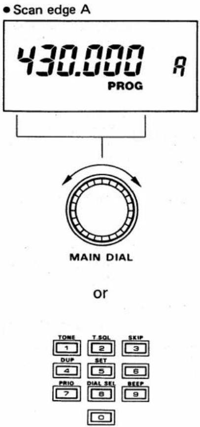
Scan edge A 430.000 R PROG MAIN DIAL or TONE T.SQL SKIP 1 2 3 DUP SET 6 4 5 6 PRIO DIAL SEL BEEP 7 8 9 0The purpose of programmed scan is to monitor a paticular section of the band. The scan edges, A and B are programmed in the following way:
NOTE: Programmed scan does not function when both frequencies on each edge are the same.
1) Push the [A] (CL) KEY to select VFO mode.
2) Push and hold the [FUNCTION] SWITCH and then push the [5] (SET) KEY to select SET mode.
3) Push the # or * KEY several times until "A" appears on the FUNCTION DISPLAY.
- "PROG" blinks on the FUNCTION DISPLAY
4) Select the upper or lower scan edge using the MAIN DIAL, or DIGIT KEYS in the same manner as selecting an operating frequency. See p. 14.
- Dial select function can be used for scan edge settings. See p. 16.
10. SET MODE
- Scan edge B
text_image
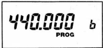
440.000 b PROG5) Push the [#] (UP) KEY once to select the other side scan edge.
- "b" appears on the FUNCTION DISPLAY.
6) Select the other side band edge in the same manner as step 4) above.
7) Push the [A] (CL) KEY to return to VFO mode, or push the [#] (UP) or [*] (DN) KEY to program the next parameter.
10 - 6 POWER SAVER
The power saver can be turned ON or OFF for data communications such as packet or AMTOR.
NOTE: When turned ON, the power saver functions on both VHF (144MHz) and UHF (430 or 440MHz) bands.
text_image
on p1) Push the [A] (CL) KEY to select VFO mode.
2) Push and hold the [FUNCTION] SWITCH and then push the 5 KEY to select SET mode.
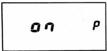
3) Push the # or * KEY several times until "P" blinks on the FUNCTION DISPLAY.
4) Rotate the MAIN DIAL to turn the power saver ON and OFF.
- "on" or "oFF" appears on the FUNCTION DISPLAY.
5) Push the [A] (CL) KEY to return to VFO mode, or push the [#] (UP) or [*] (DN) KEY to program the next parameter.
MAIN DIAL
MAINTENANCE 11.
■ TROUBLE SHOOTING
| PROBLEM | SOLUTION |
| Power does not come ON. | Be sure the connection between the battery pack and transceiver is correct and the terminals are not dirty.Be sure the battery pack is not exhausted.(p. 11) |
| No sound comes from the speaker. | Be sure the SQUELCH CONTROL is not turned too far clockwise. (p. 17)Be sure an optional UT-40 TONE SQUELCH UNIT is turned OFF. (p. 41) |
| [TX] INDICATOR does not light during transmission. | Be sure the battery pack is not exhausted.(p. 11) |
| No contact possible with another station. | Be sure the transceiver is not set in semi or full duplex operation. (pgs. 18, 37)Be sure another station is not using the tone squelch function or your tone frequency is not the same as another station (when UT-40 is installed). (p. 44) |
| Repeater cannot be accessed. | Be sure the subaudible tone frequency is correct (with IC-32AT). (p. 44)Be sure the offset frequency is correct. (p. 45)Be sure HIGH output power is selected if the repeater is located on far distance. (p. 18) |
| Frequency is not set. | Be sure the lock function is turned OFF. (p. 42)Be sure the transceiver is in VFO mode. (p. 14) |
| Scan does not operate. | Be sure the squelch is closed. (p. 26)Be sure scan edge A frequency does not equal scan edge B frequency (for programmed scan). (p. 46)Be sure all memory channels are not programmed as skip channels (for memory scan and selected band memory scan). (p. 30) |
| Howling occurs during full duplex operation. | Be sure the UHF band frequency is not set near to the third multiple of the VHF band frequency. (p. 37)Use supplied earphone. (p. 37) |
11. MAINTENANCE
■ BACKUP BATTERY
The usual life of the backup battery is more than 5 years. If the backup battery is exhausted, the transceiver operates normally but frequencies and other information cannot remain memorized when the battery pack is detached.
NOTE: Backup battery replacement must be done by an authorized Icom Dealer or Icom Service Center.
■ RESETTING THE CPU
(1) ALL RESETTING THE CPU

text_image
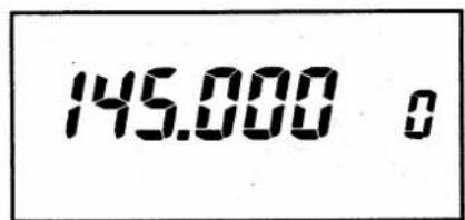
146.0 10 oU.S.A. versions
text_image
145.000 oExcept U.S.A. versions
(2) VHF BAND TUNING STEP CHANGING
NOTE: After all resetting the CPU, all information you have programmed into the transceiver will be erased.
When the FUNCTION DISPLAY displays erroneous information, the CPU should be reset before taking the transceiver to an Icom Service Center.
1) Turn power OFF.
2) Push and hold the [FUNCTION] SWITCH and then push the [A] (CL) KEY continuously until reaching step 4.
3) Turn the power ON.
4) "146.010" (U.S.A. and Southeast Asia versions) or "145.000" (other versions) appears on the FUNCTION DISPLAY.
NOTE: After VHF band tuning step changing, VHF (144MHz) band information you have programmed will be erased.
Minimum tuning steps of 5kHz or 12.5kHz on VHF band can be changed by following manner.
1) Turn power OFF.
MAINTENANCE 11.
text_image
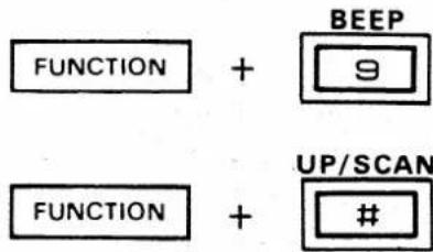
FUNCTION + BEEP 9 FUNCTION + UP/SCAN #(3) UHF BAND TUNING STEP CHANGING
2) Push and hold the [FUNCTION] SWITCH and then push the [9] or [#] KEY continuously. Then turn the power ON.
[9] : minimum tuning step 5kHz [#] : minimum tuning step 12.5kHz.
NOTE: After UHF band tuning step changing, UHF (440MHz : U.S.A. versions, 430MHz : other versions) band information you have programmed will be erased.
Minimum tuning steps of 5kHz or 12.5kHz on UHF band can be changed by following manner.
text_image
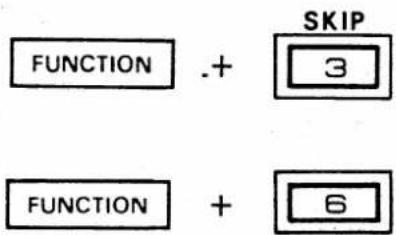
FUNCTION .+ SKIP 3 FUNCTION + 61) Turn power OFF.
2) Push and hold the [FUNCTION] SWITCH and then push the [3] or [6] KEY continuously. Then turn the power ON.
[3] : minimum tuning step 5kHz [6] : minimum tuning step 12.5kHz
12. SPECIFICATIONS
GENERAL
● Frequency coverage
| VERSION | GURANTEED RANGE | OPERATIONAL RANGE | |
| TRANSCEIVER | RECEIVER | TRANSMITTER | |
| IC-32A/ATU.S.A.version | 144.00 ~ 148.00440.00 ~ 450.00 | 138.00 ~ 174.00440.00 ~ 450.00 | 140.00 ~ 150.00440.00 ~ 450.00 |
| IC-32AAustralia version | 144.00 ~ 148.00430.00 ~ 440.00 | 144.00 ~ 148.00430.00 ~ 440.00 | 144.00 ~ 148.00430.00 ~ 440.00 |
| IC-32ATSoutheast Asia version | 144.00 ~ 148.00430.00 ~ 440.00 | 138.00 ~ 174.00430.00 ~ 440.00 | 140.00 ~ 150.00430.00 ~ 440.00 |
| IC-32EEurope version | 144.00 ~ 146.00430.00 ~ 440.00 | 144.00 ~ 146.00430.00 ~ 440.00 | 144.00 ~ 146.00430.00 ~ 440.00 |
| IC-32EItaly and Spain version | 144.00 ~ 148.00430.00 ~ 440.00 | 138.00 ~ 174.00430.00 ~ 440.00 | 140.00 ~ 150.00430.00 ~ 440.00 |
Unit : MHz
- Mode
- Tuning step increment
- Antenna impedance
● Power supply requirement
- Current drain (at 13.2V DC)
- Usable temperature range
- Dimensions
- Weight
: F3 (FM)
| IC-32A/AT | 5, 10, 15, 20, or 25kHz |
| IC-32E | 12.5 or 25kHz |
50Ω unbalanced
5.5 \~ 16.0V DC negative ground
| TX/RX | DESCRIPTION | VHF | UHF |
| Receive | Power saved typical | 10mA | 12mA |
| Max.audio output | 250mA | 250mA | |
| Transmit | HIGH power | 2.0A | 2.2A |
| LOW power | 900mA | 1.0A |
-10^ C +60^ C
: 65(W) × 180.5(H) × 35(D)mm (with BP-70)
*159(H) (with BP-3), 169(H) (with BP-4)
: 590g (with BP-70), 510g (with BP-3), 545g (with BP-4)
TRANSMITTER
• Output power (at 13.2V DC)
- Modulation system
● Max. frequency deviation
- Spurious emissions
- Microphone impedance
| VHF | UHF | |
| HIGH | 5.5W | 5.0W |
| LOW | 1.0W | 1.0W |
: Variable reactance frequency modulation
±5kHz
: Less than -60dB
2kΩ
RECEIVER
● Receiving system : Double-conversion superheterodyne
● Intermediate frequencies : 1st 30.875MHz 2nd 455kHz
- Sensitivity : Less than 0.25 V for 12dB SINAD
- Squelch sensitivity (threshold) : Less than 0.158μV
- Spurious response rejection : Less than -50dB
- Audio output power : More than 400mW at 10% distortion with an 8Ω load
• Audio output impedance : 8Ω
All stated specifications are approximate and subject to change without notice or obligation.
Count on us!