
MSS1 - Synthesizer YAMAHA - Kostenlose Bedienungsanleitung
Finden Sie kostenlos die Bedienungsanleitung des Geräts MSS1 YAMAHA als PDF.

| Produkttyp | MIDI-Synchronizer (Synthesizer-Steuergerät) |
| Marke | YAMAHA |
| Modell | MSS1 |
| Abmessungen (B x H x T) | 439 x 73,5 x 286 mm |
| Gewicht | 3,8 kg |
| Stromversorgung | USA/Kanada: 120 V AC, 50/60 Hz, 15 W; Allgemein: 220–240 V AC, 50/60 Hz, 15 W |
| Bildschirm | LCD 16 Zeichen x 1 Zeile, hintergrundbeleuchtet; LED 7-Segment (20 Stellen) |
| SMPTE-Formate | 30, 30 Drop-Frame, 25 und 24 fps |
| Speicherkapazität | 16 kByte (Lithium-Batterie gepuffert); max. 7178 Schläge (7168 pro Bank); max. 150 Tempoänderungen; max. 1793 MIDI-Ereignisse |
| Anschlüsse | CLICK IN, SMPTE IN/OUT, METRONOME OUT, FOOT SW IN, MIDI IN, MIDI OUT (x2), RAM-CARTRIDGE-Slot |
| MIDI-Funktionen | Taktgeber, Start/Stop/Continue, Song-Positionszeiger, Song-Auswahl, Bulk-Dump, Programmwechsel, Controller |
| Hauptfunktionen | SMPTE-Synchronisation, Tempoaufnahme (3 Methoden), Kettenwiedergabe, MIDI-Ereignisaufnahme/-wiedergabe, unabhängiger Spielmodus, Metronom |
| Zubehör im Lieferumfang | MIDI-Kabel (1x), RCA-Phonostecker-Adapter (2x) |
| Reinigung | Mit einem weichen, trockenen Tuch abwischen; keine Lösungsmittel wie Benzin oder Verdünner verwenden |
| Sicherheitshinweise | Übermäßige Hitze, Feuchtigkeit, Staub und Vibrationen vermeiden; keine Reparaturen selbst durchführen; vor Anschlussarbeiten Gerät ausschalten; richtige Netzspannung verwenden |
| Batterie | Lithium-Batterie für Speichererhaltung (ca. 5 Jahre Lebensdauer); Austausch nur durch Fachpersonal |
| Reparatur | Keine vom Benutzer wartbaren Teile; Service nur durch autorisiertes Yamaha-Personal |
Häufig gestellte Fragen - MSS1 YAMAHA
Benutzerfragen zu MSS1 YAMAHA
0 Frage zu diesem Gerät. Beantworten Sie die, die Sie kennen, oder stellen Sie Ihre eigene.
Eine neue Frage zu diesem Gerät stellen
Laden Sie die Anleitung für Ihr Synthesizer kostenlos im PDF-Format! Finden Sie Ihr Handbuch MSS1 - YAMAHA und nehmen Sie Ihr elektronisches Gerät wieder in die Hand. Auf dieser Seite sind alle Dokumente veröffentlicht, die für die Verwendung Ihres Geräts notwendig sind. MSS1 von der Marke YAMAHA.
BEDIENUNGSANLEITUNG MSS1 YAMAHA
YAMAHA
MSS1
MIDI SYNCHRONIZER
SYNCHRONISEUR MIDI
MIDI SYNCHRONIZER
OWNER'S MANUAL
MANUEL D'UTILISATION
BEDIENUNGSANLEITUNG
Congratulations on your acquisition of a Yamaha MSS1 MIDI Synchronizer! The MSS1 can precisely lock any clock-driven MIDI device to SMPTE time code replayed from a multitrack, video tape or other SMPTE source, and it's fully compatible with all four SMPTE formats (30, 30 drop-frame, 25 or 24 frames/sec.). It even has its own precision SMPTE time code generator built-in. A large 10-bank song memory offers plenty of capacity for any application, and a chain mode automatically plays banks in sequence allowing tempo and other changes to be made in the course of a single recording. Internal memory data can also be saved to external RAM4 data cartridges for high-volume, long-term storage. For extra MIDI control versatility, the MSS1 can be programmed to transmit MIDI program change and control change data at any specified times. A number of utility and control functions are provided to make overall operation as easy and as versatile as possible.
In order to obtain optimum performance from your MSS1, we urge you to continue reading this operation manual.
CONTENTS
PRECAUTIONS 4
1: CONTROLS AND CONNECTIONS 5
Controls and Displays 5
Connector Panel 7
2: TIME CODE 8
SMPTE TIME CODE 8
SETTING THE TIME CODE FRAME RATE 8
GENERATING AND RECORDING THE TIME CODE 9
THE SMPTE READ TEST 10
3: RECORDING THE SYNC TEMPO DATA.... 11
TEMPO DATA AND THE MSS1 INTERNAL MEMORY CONFIGURATION.... 11
SELECTING AND NAMING A BANK FOR RECORDING 11
NAMING THE CURRENTLY SELECTED BANK 12
SETTING THE TIME SIGNATURE 13
Setting the Starting Time Signature.... 13
Inserting a Time Signature Change.... 14
Deleting a Time Signature Change 15
TEMPO RECORDING METHOD 1 - TIME CODE + CLICK TRACK FROM TAPE.... 15
TEMPO RECORDING METHOD 2 — TIME CODE FROM TAPE OR
INTERNAL TIME CODE + MANUAL TAP 16
Time Code from Tape + Manual Tap 16
Internal Time Code + Manual Tap.... 18
TEMPO RECORDING METHOD 3 — STEP RECORDING.... 19
RECORDING WITH A COUNT-IN 20
4: PLAYBACK 21
NON-SYNC PLAYBACK 21
CHASE-MODE SYNCHRONIZED PLAYBACK 21
STARTING PLAYBACK FROM A SPECIFIED POSITION 22
Time Cue 22
Song Cue 23
CHAIN EDIT & PLAYBACK 24
5: EDITING 25
LOCATING A SPECIFIED MEASURE/BEAT USING THE SONG CUE FUNCTION.... 25
REPLACING TEMPO DATA 25
COPYING TEMPO DATA 26
DELETING TEMPO DATA.... 26
INSERTING TEMPO DATA 27
BANK DELETE 27
BANK COPY 28
SMPTE OFFSET 28
SONG SELECT 29
6: MIDI EVENT RECORDING, PLAYBACK AND EDITING 30
TO SWITCH INTO AND OUT OF THE MIDI EVENT MODE 30
NAMING THE MIDI EVENT SEQUENCE.... 30
MIDI EVENT SEQUENCE RECORDING METHOD 1 — TIME CODE FROM TAPE OR
INTERNAL TIME CODE + MANUAL TAP 31
Time Code from Tape + Manual Tap 31
Internal Time Code + Manual Tap 32
MIDI EVENT SEQUENCE RECORDING METHOD 2 - STEP RECORDING.... 33
EDITING A MIDI EVENT SEQUENCE 34
Locating a Specific Event Using the "STEP CUE" Function 35
Event Replace 36
Event Delete 36
Event Insert 36
Deleting All Steps.... 37
7: EXTERNAL DATA STORAGE AND RETRIEVAL 38
FORMATTING A NEW RAM4 DATA CARTRIDGE.... 38
SAVE TO CARTRIDGE OR MIDI BULK DUMP 38
LOAD FROM CARTRIDGE OR RECEIVE BULK DUMP 39
8: OTHER FUNCTIONS 40
METRONOME 40
TOTAL TIME 40
INTERVAL TIME.... 41
DEVICE NUMBER 42
INDEPENDENT PLAY 42
9: MSS1 SPECIFICATIONS 43
MIDI DATA 44
PRECAUTIONS
1. AVOID EXCESSIVE HEAT, HUMIDITY, DUST AND VIBRATION
Keep the unit away from locations where it is likely to be exposed to high temperatures or humidity -- such as near radiators, stoves, etc. Also avoid locations which are subject to excessive dust accumulation or vibration which could cause mechanical damage.
2. AVOID PHYSICAL SHOCKS
Strong physical shocks to the unit can cause damage. Handle it with care.
3. DO NOT OPEN THE CASE OR ATTEMPT REPAIRS OR MODIFICATIONS YOURSELF
This product contains no user-serviceable parts. Refer all maintenance to qualified Yamaha service personnel. Opening the case and/or tampering with the internal circuitry will void the warranty.
4. MAKE SURE POWER IS OFF BEFORE MAKING OR REMOVING CONNECTIONS
Always turn the power OFF prior to connecting or disconnecting cables. This is important to prevent damage to the unit itself as well as other connected equipment.
5. HANDLE CABLES CAREFULLY
Always plug and unplug cables -- including the AC cord -- by gripping the connector, not the cord.
6. CLEAN WITH A SOFT DRY CLOTH
Never use solvents such as benzine or thinner to clean the unit. Wipe clean with a soft, dry cloth.
7. ALWAYS USE THE CORRECT POWER SUPPLY
Make sure that the power supply voltage specified on the rear panel matches your local AC mains supply. U.S./Canadian Model: 110 -- 120 V AC, 50/60 Hz General Model: 220 -- 240 V AC, 50/60 Hz
8. ELECTRICAL INTERFERENCE
Since the MSS1 contains digital circuitry, it may cause interference and noise if placed too close to TV sets, radios or similar equipment. If such a problem does occur, move the MSS1 further away from the affected equipment.
9. BACKUP BATTERY
The MSS1 contains a long-life lithium battery which maintains the contents of the RAM memory even when the unit is turned OFF. With normal use the battery should last for approximately 5 years. If battery failure occurs, have the battery replaced by a qualified Yamaha service center. Do not attempt to replace the battery yourself!
10. POWER-ON PROCEDURE
Always turn the MSS1 power ON first in a chain of connected MIDI devices. This is to prevent random data sometimes generated at power-on from being transmitted to subsequent devices.
1: CONTROLS AND CONNECTIONS
Controls and Displays
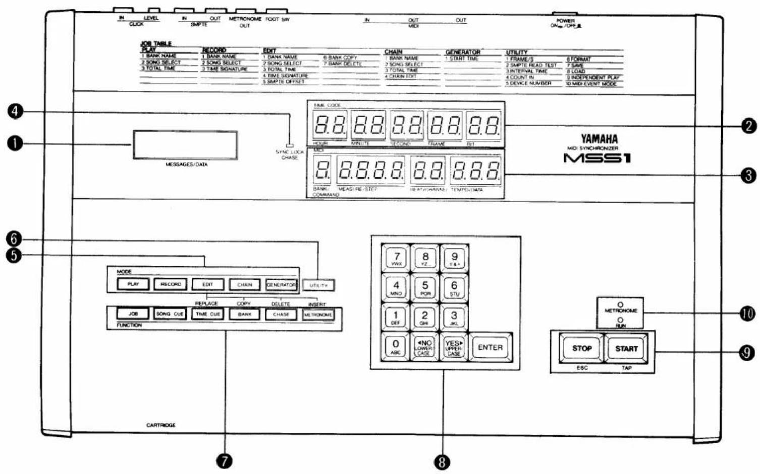
① MESSAGES/DATA Display (LCD)
This 16-character backlit liquid-crystal display shows the MSS1's operating modes, some programming data and user prompts when needed.
② Time Code Display
The upper LED TIME CODE display shows SMPTE time code values in hours, minutes, seconds, frames and bits.
③ MIDI Data Display
In the recording and playback modes, the lower LED MIDI display shows bank, measure, beat and tempo data. In the MIDI event mode, the same display areas show command type, step number, MIDI channel number and command data.
④ SYNC LOCK Indicator
This green LED indicator shows whether the MSS1 is in its internal non-sync or sync (chase) mode. The SYNC LOCK indicator is off while the MSS1 is waiting for time code data from tape, and lights when the MSS1 is locked to the received data.
⑤ Mode Keys
These 5 keys select the MSS1's PLAY, RECORD, EDIT, CHAIN and GENERATOR modes.
⑥ UTILITY Key
The UTILITY key selects a list of utility functions including data storage and retrieval, and a SMPTE read test.
⑦ Function Keys
These 6 keys access the JOB, SONG CUE, TIME CUE, BANK, CHASE and METRONOME keys. While in the EDIT mode, the last 4 keys in this row access the REPLACE, COPY, DELETE and INSERT editing functions.
⑧ 10-key Numeric Entry Pad
A 10-key numeric entry pad for entering virtually all types of data required by the MSS1 is included on the front panel. The
⑨ START & STOP Keys
The START and STOP keys, as their names imply, START and STOP most of the MSS1's major functions such as recording and playback. The STOP key is also used to cancel or exit from almost any function.
⑩ RUN and METRONOME LEDs
The RUN LED lights while the MSS1 is recording or playing, and the METRONOME LED provides a visual tempo display.
Connector Panel
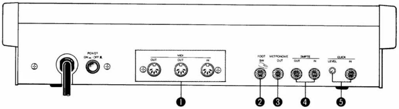
① MIDI IN/OUT/OUT Connectors
The MIDI IN connector receives MIDI data from an external MIDI device. This is useful for reloading data which has been bulk-dumped from the MSS1 to an external MIDI data recorder or similar storage device using the MSS1's MIDI BULK OUT function. The two MIDI OUT connectors transmit MIDI timing data and control change/program change messages to the MIDI device to be synchronized by the MSS1. Internally generated MIDI data is selectively merged with data received at the MIDI IN connector and delivered via MIDI OUT.
② FOOT SW Jack
A Yamaha FC4/FC5 footswitch or equivalent connected to this jack can be used for foot control of the MSS1 START and STOP functions.
③ METRONOME OUT Jack
This 1/4" mono phone jack transmits the MSS1 metronome signal to an external amplifier or tape recorder. The internal metronome speaker is shut off when a plug is inserted into this jack.
④ SMPTE IN and OUT Jacks
These 1/4" mono phone jacks receive and transmit the SMPTE time code from and to the video or audio recorder used with the MSS1. The SMPTE OUT jack transmits SMPTE time code from MSS1's internal generator.
⑤ CLICK IN Jack and LEVEL Control
The 1/4" mono CLICK IN phone jack receives the click track signal from the tape to which the MIDI device is to be synchronized in order to compute and generate appropriate MIDI timing data. The LEVEL control adjusts the sensitivity of the CLICK IN input for reliable operation.
2: TIME CODE
SMPTE TIME CODE
"SMPTE" is an acronym that stands for Society of Motion Picture and Television Engineers, and the SMPTE Time Code is a standard adopted by this organization in 1969 for the synchronization of audio, video and film reproduction equipment (although its primary use was in video). SMPTE time code is an "absolute" time addressing system since it consists of data which specifies a precise time in hours, minutes, seconds and frames. The number of frames per second used depends on the application: 30 frames per second (fps) for monochrome NTSC-standard TV, 29.97 frames per second (drop-frame) for color NTSC-standard TV, 25 frames per second for European PAL-standard TV, and 24 frames per second for film. Thus, using the 30 fps rate, 30 complete time addresses (hours, minutes, seconds and frames) are recorded on every second's worth of tape. A single time address is generally referred to as a "frame," and each time-code frame consists of 80 data bits.
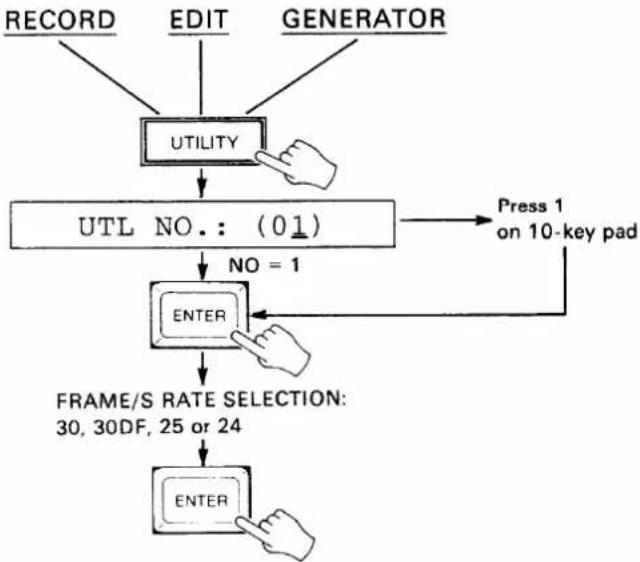
SETTING THE TIME CODE FRAME RATE
Before using the MSS1 to record or read time code, it must be set to use the appropriate frame rate. The rate you choose will be determined by your own application. If the rate is unimportant (i.e. you won't be dealing with tapes or equipment which function with a specific or variable rates), then the factory-programmed 30 fps rate is a good choice.
- From either the RECORD, EDIT or GENERATOR mode (if you are not in one of these modes, first press the RECORD, EDIT or GENERATOR key), press the UTILITY key.
- Note that the FRAME/S job is number 1 in the UTILITY job list printed at the top right of the panel. If a number other than (01) appears following the "UTL NO.:" display on the LCD, press the "1" key on the 10-key numeric entry pad.
- Press the ENTER key to call the selected utility job.
- Use the NO and YES keys to select either the 30, 30DF (drop frame), 25 or 24 FRAME/S rate.
- Press the ENTER key to set the selected frame rate and exit from the UTILITY mode.
- Press the STOP key to exit and cancel at any stage before the last step is performed.
flowchart
graph TD
    A["RECORD"] --> B["UTILITY"]
    C["EDIT"] --> B
    D["GENERATOR"] --> B
    B --> E["UTL NO.: (01)"]
    E --> F["NO = 1"]
    F --> G["ENTER"]
    G --> H["FRAME/S RATE SELECTION: 30, 30DF, 25 or 24"]
    H --> I["ENTER"]
    I --> J["Press 1 on 10-key pad"]
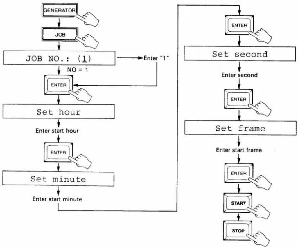
GENERATING AND RECORDING THE TIME CODE
If you're dealing with tape -- audio or video -- on which the time code has already been recorded, this step is not necessary. If you're starting with blank tape, however, the first step is to record the time code on one track of the tape. On a multitrack audio tape one of the outermost tracks are usually used -- normally the highest-numbered track. Time code is recorded on an audio or "cue" track of a video tape. You should always record a segment of time code just a little longer than the music to be worked on, or record time code for the entire length of the tape.
- Make sure the SMPTE OUT terminal is connected to the appropriate input on your audio or video recorder.
- Press the GENERATOR key.
- Press the JOB key.
- Note that START TIME is job number 1 on the GENERATOR job list printed at the top of the MSS1 panel. If a number other than (1) appears following the "JOB NO.:" display on the LCD, enter "1" via the 10-key numeric entry pad.
- Press the ENTER key to call the START TIME job.
- Enter the desired start hour via the 10-key pad when the "Set hour" display appears on the LCD, then press ENTER.
- Enter the desired start minute via the 10-key pad when the "Set minute" display appears on the LCD, then press ENTER.
- Enter the desired start second via the 10-key pad when the "Set second" display appears on the LCD, then press ENTER.
- Enter the desired start frame via the 10-key pad when the "Set frame" display appears on the LCD, then press ENTER.
- Press the START key to begin time code generation from the specified time.
- Press the STOP key to end time code generation.
- Press the STOP key to exit and cancel at any stage before the last step is performed.
flowchart
graph TD
    A["GENERATOR"] --> B["JOB"]
    B --> C["JOB NO.: (1)"]
    C --> D["NO = 1"]
    D --> E["ENTER"]
    E --> F["Set hour"]
    F --> G["Enter start hour"]
    G --> H["ENTER"]
    H --> I["Set minute"]
    I --> J["Enter start minute"]
    J --> K["ENTER"]
    K --> L["SET frame"]
    L --> M["Enter start frame"]
    M --> N["ENTER"]
    N --> O["START"]
    O --> P["STOP"]
    P --> K
    Q["Enter "1"] --> D
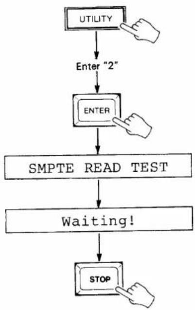
THE SMPTE READ TEST
This handy test has been incorporated to let you check that the time code has been properly recorded on the tape and can be read accurately.
- Make sure that the appropriate output from the recorder is connected to the MSS1 SMPTE IN terminal. The MSS1 will accept time code signal levels between about -24 and +4 dB.
- Press the UTILITY key and enter the number "2" via the 10-key pad.
- Press ENTER: "SMPTE READ TEST" will appear for a few seconds, then the "Waiting!" display will appear.
- Rewind and play back the tape on which the time code track has been recorded.
- If the time code is properly read the SYNC LOCK indicator will light and the received time code will be displayed on the TIME CODE LED display.
- Press the STOP key to exit the SMPTE READ TEST.
flowchart
graph TD
    A["UTILITY"] --> B["Enter "2""]
    B --> C["ENTER"]
    C --> D["SMPTE READ TEST"]
    D --> E["Waiting!"]
    E --> F["STOP"]
3: RECORDING THE SYNC TEMPO DATA
TEMPO DATA AND THE MSS1 INTERNAL MEMORY CONFIGURATION
The main purpose of the MSS1 is to generate MIDI timing signals which are synchronized to a SMPTE time code signal received from an audio or video tape. The MIDI timing signals generated are used to synchronize MIDI equipment (sequencers, rhythm programmers, a digital mixer such as the Yamaha DMP7 Digital Mixing Processor, etc.) to material recorded on tape. Since the SMPTE time code provides a precise time index but no tempo information, the tempo data required by the music being worked on must be recorded into the MSS1's internal memory. Tempo data can be recorded using any of the three methods outlined below.
The MSS1 has 10 internal memory "BANKS," each of which can be individually selected, given a title, and used to record tempo data. The data for ten 10 individual "pieces" can therefore be separately recorded, selected and played back. The BANKS can also be played back in sequence using the CHAIN PLAY function described in the next section. A total of 7178 beats can be recorded in all 10 BANKS (max. 7168 in one bank). In terms of playing time, that's approximately 60 minutes at a tempo of 120 in 4/4 time.
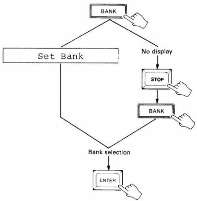
SELECTING AND NAMING A BANK FOR RECORDING
Selecting a Bank (0 - 9)
- Press the BANK key. If the "Set bank" display does not appear on the LCD, press the STOP key to exit whichever mode the MSS1 was in and press the BANK key again.
- Enter the number of the desired bank via the 10-key pad (0 — 9). The entered bank number will be displayed on the BANK/COMMAND area of the MIDI data LED display. The YES> and <NO keys can also be used to move between banks.
- Press ENTER to set the selected bank and exit the bank selection mode.
- Press the STOP key to exit and cancel at any stage before the last step. is performed.
flowchart
graph TD
    A["BANK"] --> B["Set Bank"]
    B --> C{No display}
    C --> D["STOP"]
    D --> E["BANK"]
    E --> F{Bank selection}
    F --> G["ENTER"]
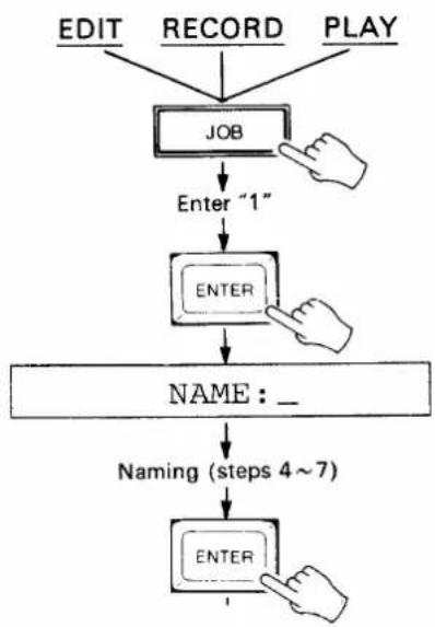
NAMING THE CURRENTLY SELECTED BANK
Although it's not necessary to do this, giving an appropriate name to each bank recorded makes it easier to identify their contents later (e.g. "INTRO," "BALLAD," etc.). Bank names can be a maximum of 8 characters in length.
- In either the EDIT, RECORD or PLAY mode, press the JOB key.
- Note that BANK NAME is number 1 in the EDIT job list printed at the top of the MSS1 panel. Enter the number "1" via the 10-key pad.
- Press ENTER to select the BANK NAME EDIT job. The "NAME:" display will appear and an underline cursor will appear under the first character position. A down-arrow in the rightmost character position indicates that the lower-case character mode is selected, while an up-arrow indicates the upper-case mode.
- Use the NO and YES keys to select the upper or lower-case character set.
- Enter the first character of the bank name. Each of the numeric entry keys (0 - 9) accesses a number and three characters in sequence, as follows:
| KEY | ACCESSES (Upper case mode) |
| 0 | 0 A B C |
| 1 | 1 D E F |
| 2 | 2 G H I |
| 3 | 3 J K L |
| 4 | 4 M N O |
| 5 | 5 P Q R |
| 6 | 6 S T U |
| 7 | 7 V W X |
| 8 | 8 Y Z □ (Space) |
| 9 | 9 # & + |
- Move the cursor to the next character position by pressing the START key. The STOP key can be used to move the cursor back to a previous character position.
- Enter the next character and continue until the name is complete.
- Press ENTER to set the name and exit the BANK NAME mode.
- If job 1 (BANK NAME) is selected in the CHAIN PLAY mode, the programmed bank name will be displayed for a few seconds but no changes can be made.
flowchart
graph TD
    A["EDIT"] --> D["JOB"]
    B["RECORD"] --> D["JOB"]
    C["PLAY"] --> D["JOB"]
    D -->|Enter "1"| E["ENTER"]
    E --> F["NAME : _"]
    F --> G["Naming (steps 4~7)"]
    G --> H["ENTER"]
SETTING THE TIME SIGNATURE
The MSS1 must be programmed with the time signature of the piece in order to produce the correct MEASURE and BEAT displays as well as MIDI song position pointer output. The MIDI song position pointer transmitted via the MIDI OUT terminal is used to lock the measure and beat positions of compatible MIDI sequencers, drum machines and other equipment to those of the MSS1, so the MIDI device driven will accurately "follow" the operation of the MSS1. The MSS1 permits changing time signatures during the course of a piece by specifying different time signatures at different measure numbers.
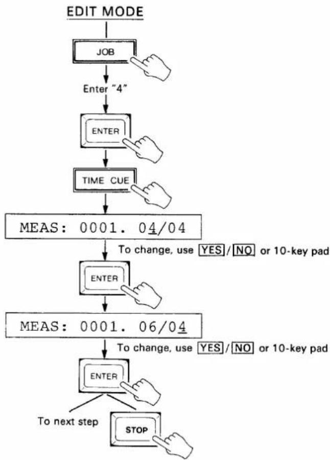
Setting the Starting Time Signature
- In the EDIT mode (press the EDIT key) press the JOB key and select job number 4: TIME SIGNATURE (press JOB, enter "4" then press ENTER). The default 4/4 time signature for measure 1 will be displayed on the LCD.
- To change the starting (measure 1) time signature, press the EDIT-REPLACE (TIME CUE) key.
- Select the first figure of the time signature using the YES and NO keys, or directly enter the number via the 10-key pad (numbers 1 through 16 are acceptable).
- Press ENTER.
- Select the second figure of the time signature using the YES and NO keys, or enter the figure directly via the 10-key pad (2, 4, 8 and 16 are acceptable).
- Press ENTER.
- Press the STOP key to exit the time signature mode, or go on to the "Inserting a Time Signature Change" steps below.
flowchart
graph TD
    A["EDIT MODE"] --> B["JOB"]
    B --> C["Enter "4""]
    C --> D["ENTER"]
    D --> E["TIME CUE"]
    E --> F["MEAS: 0001. 04/04"]
    F --> G["ENTER"]
    G --> H["MEAS: 0001. 06/04"]
    H --> I["ENTER"]
    I --> J["To next step"]
    I --> K["STOP"]
    style F fill:#f9f,stroke:#333
    style H fill:#f9f,stroke:#333
    style I fill:#f9f,stroke:#333
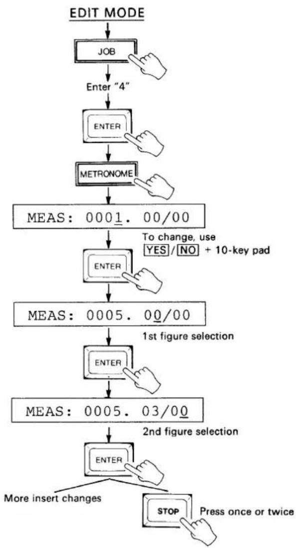
Inserting a Time Signature Change
- After entering the EDIT mode and selecting job 4 (see step 1, above), press the EDIT-INSERT (METRONOME) key. Measure and time signature values of zero will appear on the LCD.
- Select the measure number at which the time signature change is to occur using the YES> and <NO keys, or enter the measure number directly using the 10-key pad.
- Press ENTER.
- Select the first figure of the time signature using the YES and NO keys, or directly enter the number via the 10-key pad (numbers 1 through 16 are acceptable).
- Press ENTER.
- Select the second figure of the time signature using the YES and NO keys, or enter the figure directly via the 10-key pad (2, 4, 8 and 16 are acceptable).
- Press ENTER.
- Press the STOP key twice to exit the time signature mode, or go back to step 2 to insert more changes.
flowchart
graph TD
    A["EDIT MODE"] --> B["JOB"]
    B --> C["Enter "4""]
    C --> D["ENTER"]
    D --> E["METRONOME"]
    E --> F["MEAS: 0001.00/00"]
    F --> G["ENTER"]
    G --> H["MEAS: 0005.00/00"]
    H --> I["ENTER"]
    I --> J["MEAS: 0005.03/00"]
    J --> K["ENTER"]
    K --> L["More insert changes"]
    K --> M["STOP Press once or twice"]
    style F fill:#f9f,stroke:#333
    style H fill:#f9f,stroke:#333
    style J fill:#f9f,stroke:#333
    style K fill:#f9f,stroke:#333
    style L fill:#ccf,stroke:#333
    style M fill:#ccf,stroke:#333
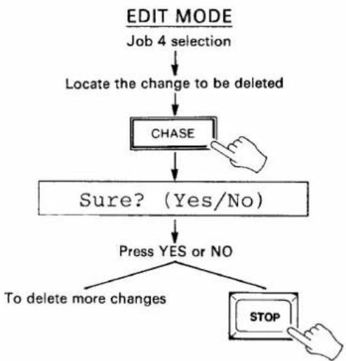
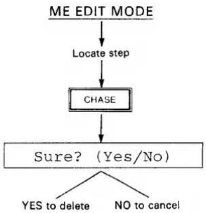
Deleting a Time Signature Change
- After entering the EDIT mode and selecting job 4 (see step 1, above), use the YES> and <NO keys to scroll forward and backward through the list of time signature changes until you locate the change to be deleted.
- Press the EDIT-DELETE (CHASE) key. The MSS1 will ask you to confirm your intention to delete the selected time signature change with the "Sure? (Yes/No)" display.
- Press the YES key to delete the selected change, or the NO key to cancel.
- Press the STOP key to exit the time signature mode, or go back to step 1 to delete more changes.
- The measure 1 time signature can not be deleted. It can only be REPLACED as described in "Setting the Starting Time Signature," above.
flowchart
graph TD
    A["EDIT MODE\nJob 4 selection"] --> B["Locate the change to be deleted"]
    B --> C["CHASE"]
    C --> D{Sure? (Yes/No)}
    D -->|Yes| E["Press YES or NO"]
    D -->|No| F["To delete more changes"]
    E --> G["STOP"]
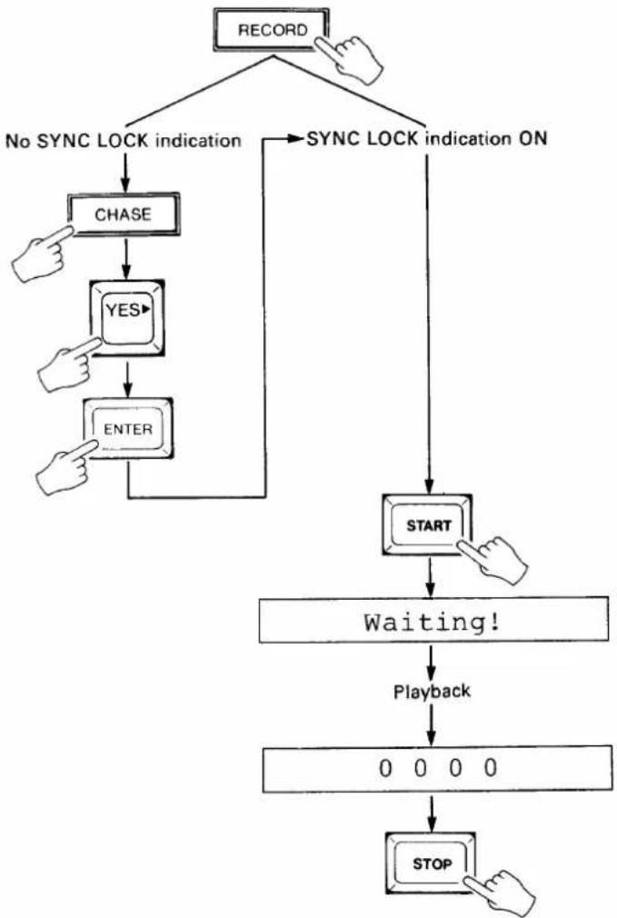
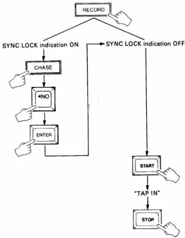
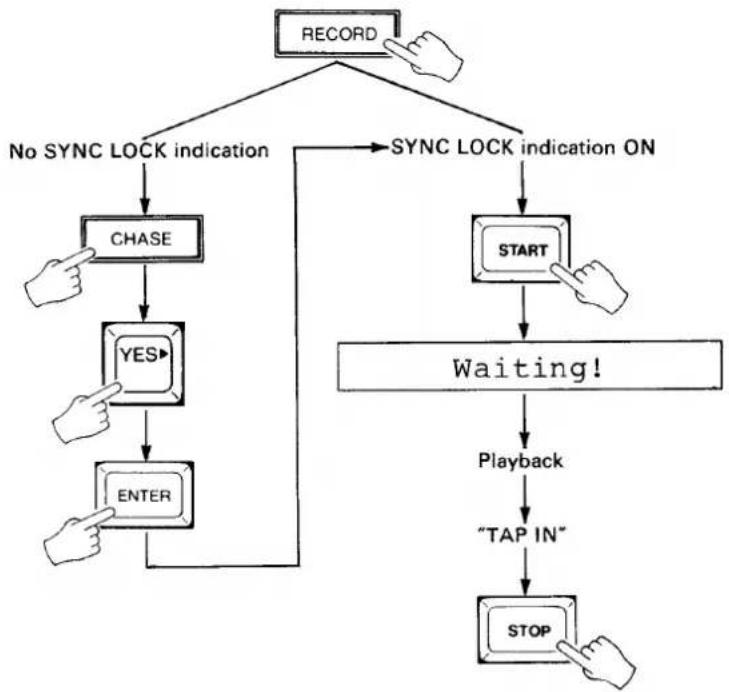
TEMPO RECORDING METHOD 1 — TIME CODE + CLICK TRACK FROM TAPE
This method of recording tempo data is ideal when you have both a time code track and click (tempo) track recorded on the master tape. The click track can be created by recording the metronome output from a MIDI sequence recorder or similar device.
- Make sure that the outputs from both the time code track and click track on the recorder are connected to the SMPTE IN and CLICK IN terminals on the MSS1, respectively.
- Press the RECORD key to enter the RECORD mode.
- If the SYNC LOCK indicator is not lit, press the CHASE key, press the YES key to select
, then press ENTER to set the CHASE mode ON and return to the RECORD mode. The SYNC LOCK indicator should now be lit. - Press the START key. The SYNC LOCK indicator will go out and the "Waiting!" display will appear on the LCD.
- Play back the tape from a point a few seconds before the beginning of the music to be recorded. When the MSS1 locks on to the received time code, the SYNC LOCK indicator will light and the TIME CODE LED display will display the received time code data. When the click track is received the MIDI MEASURE, BEAT and TEMPO displays will follow according to the programmed
time signature (see "SETTING THE TIME SIGNATURE," above). As each beat is recorded, the remaining memory display to the right of the LCD is decremented by one. Recording is stopped automatically when the memory display reaches 0000.
- When the click track ends, press the MSS1 STOP key to automatically exit the RECORD mode and enter the PLAY mode. Stop and rewind the tape recorder.
flowchart
graph TD
    A["RECORD"] --> B["No SYNC LOCK indication"]
    A --> C["SYNC LOCK indication ON"]
    B --> D["CHASE"]
    D --> E["YES"]
    E --> F["ENTER"]
    F --> G["START"]
    G --> H["Waiting!"]
    H --> I["Playback"]
    I --> J["0 0 0 0"]
    J --> K["STOP"]
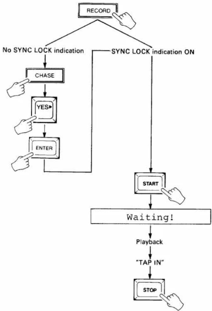
TEMPO RECORDING METHOD 2 — TIME CODE FROM TAPE OR INTERNAL TIME CODE + MANUAL TAP
These two similar recording methods are ideal if a recorded click track is not available. The second version permits recording tempo data without receiving a time code signal from the master tape, and thus saves time as well as wear-and-tear on the master tape.
Time Code from Tape + Manual Tap
-
Make sure that the output from the time code track on the recorder is connected to the SMPTE IN terminal on the MSS1.
-
Press the RECORD key to enter the RECORD mode.
-
If the SYNC LOCK indicator is not lit, press the CHASE key, press the YES key to select
, then press ENTER to set the CHASE mode ON and return to
the RECORD mode. The SYNC LOCK indicator should now be lit.
-
Press the START key. The SYNC LOCK indicator will go out and the "Waiting!" display will appear on the LCD.
-
Play back the tape from a point a few seconds before the beginning of the music to be recorded. When the MSS1 locks on to the received time code, the SYNC LOCK indicator will light and the TIME CODE LED display will display the received time code data.
-
Tap the START key at the desired tempo to record the tempo data. Tap-enter the tempo for the entire length of the piece to be recorded. The MIDI MEASURE, BEAT and TEMPO displays will follow according to the programmed time signature (see "SETTING THE TIME SIGNATURE," on page 13). As each beat is recorded, the remaining memory display to the right of the LCD is decremented by one. Recording is stopped automatically when the memory display reaches 0000.
-
When the tempo for the entire piece has been "tapped in," press the MSS1 STOP key to automatically exit the RECORD mode and enter the PLAY mode. Stop and rewind the tape recorder.
flowchart
graph TD
    A["RECORD"] --> B["No SYNC LOCK INDICATION"]
    A --> C["SYNC LOCK INDICATION ON"]
    B --> D["CHASE"]
    D --> E["YES"]
    E --> F["ENTER"]
    F --> G["START"]
    G --> H["Waiting!"]
    H --> I["Playback"]
    I --> J["TAP IN"]
    J --> K["STOP"]
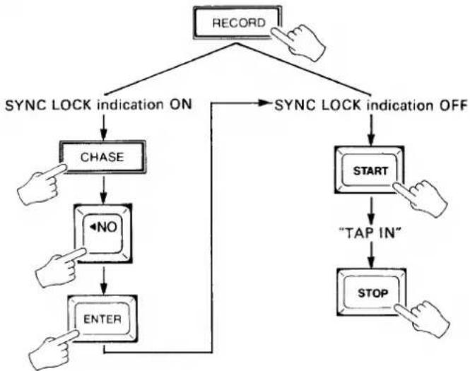
Internal Time Code + Manual Tap
- Press the RECORD key to enter the RECORD mode.
- If the SYNC LOCK indicator is lit, press the CHASE key, press the NO key to select
, then press ENTER to set CHASE OFF and return to the RECORD mode. The SYNC LOCK indicator should now be out. - Press the START key. The internal time code generator will begin running and the time code will be displayed on the TIME CODE LED display.
- Tap the START key at the desired tempo to record the tempo data. Tap-enter the tempo for the entire length of the piece to be recorded. The MIDI MEASURE, BEAT and TEMPO displays will follow according to the programmed time signature (see "SETTING THE TIME SIGNATURE," on page 13). As each beat is recorded, the remaining memory display to the right of the LCD is decremented by one. Recording is stopped automatically when the memory display reaches 0000.
- When the tempo for the entire piece has been "tapped in," press the MSS1 STOP key to automatically exit the RECORD mode and enter the PLAY mode.
flowchart
graph TD
    A["RECORD"] --> B{SYNC LOCK indication ON}
    B --> C["CHASE"]
    C --> D["<NO"]
    D --> E["ENTER"]
    E --> F["START"]
    F --> G["TAP IN"]
    G --> H["STOP"]
    H --> I["NOT"]
    I --> J["START"]
    J --> K["SOYA"]
    K --> L["CHASE"]
    L --> M["CHASE"]
    M --> N["CHASE"]
    N --> O["CHASE"]
    O --> P["CHASE"]
    P --> Q["CHASE"]
    Q --> R["CHASE"]
    R --> S["CHASE"]
    S --> T["CHASE"]
    T --> U["CHASE"]
    U --> V["CHASE"]
    V --> W["CHASE"]
    W --> X["CHASE"]
    X --> Y["CHASE"]
    Y --> Z["CHASE"]
    Z --> AA["CHASE"]
    AA --> AB["CHASE"]
    AB --> AC["CHASE"]
    AC --> AD["CHASE"]
    AD --> AE["CHASE"]
    AE --> AF["CHASE"]
    AF --> AG["CHASE"]
    AG --> AH["CHASE"]
    AH --> AI["CHASE"]
    AI --> AJ["CHASE"]
    AJ --> AK["CHASE"]
    AK --> AL["CHASE"]
    AL --> AM["CHASE"]
    AM --> AN["CHASE"]
    AN --> AO["CHASE"]
    AO --> AP["CHASE"]
    AP --> AQ["CHASE"]
    AQ --> AR["CHASE"]
    AR --> AS["CHASE"]
    AS --> AT["CHASE"]
    AT --> AU["CHASE"]
    AU --> AV["CHASE"]
    AV --> AW["CHASE"]
    AW --> AX["CHASE"]
    AX --> AY["CHASE"]
    AY --> AZ["CHASE"]
    AZ --> BA["CHASE"]
    BA --> BB["CHASE"]
    BB --> BC["CHASE"]
    BC --> BD["CHASE"]
    BD --> BE["CHASE"]
    BE --> BF["CHASE"]
    BF --> BG["CHASE"]
    BG --> BH["CHASE"]
    BH --> BI["CHASE"]
    BI --> BJ["CHASE"]
    BJ --> BK["CHASE"]
    BK --> BL["CHASE"]
    BL --> BM["CHASE"]
    BM --> BN["CHASE"]
    BN --> BO["CHASE"]
    BO --> BP["CHASE"]
    BP --> BQ["CHASE"]
    BQ --> BR["CHASE"]
    BR --> BS["CHASE"]
    BS --> BT["CHASE"]
    BT --> BU["CHASE"]
    BU --> BV["CHASE"]
    BV --> BW["CHASE"]
    BW --> BX["CHASE"]
    BX --> BY["CHASE"]
    BY --> BZ["CHASE"]
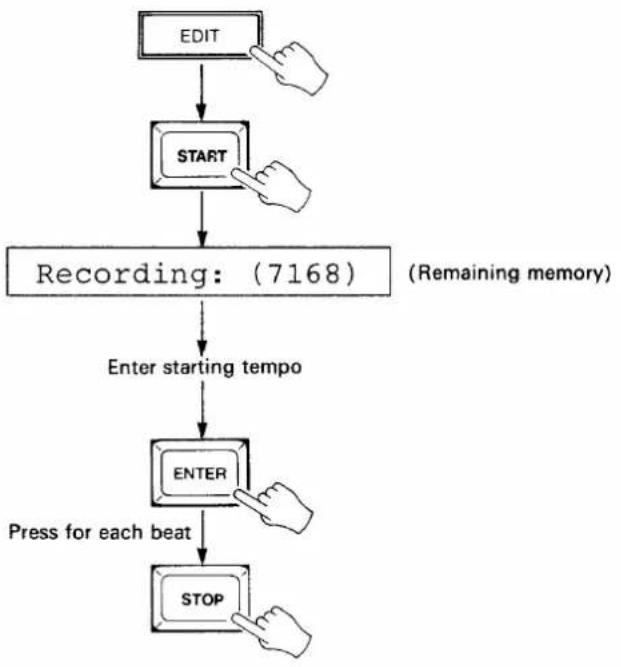
TEMPO RECORDING METHOD 3 — STEP RECORDING
This method will only work if the currently selected bank contains no previously-recorded data.
- Press the EDIT key to enter the EDIT mode.
- Press the START key. The "Recording:(7168)" display will appear on the LCD, the TIME CODE display will go out and the MIDI TEMPO display will go out.
- Enter the starting tempo via the 10-key pad. The TEMPO figure may also be incremented or decremented using the YES> and <NO keys.
- Press the ENTER key once for each beat you wish to record at the previously entered tempo. The MIDI MEASURE and BEAT displays will advance according to the programmed time signature (see "SETTING THE TIME SIGNATURE," on page 13). As each beat is recorded, the remaining memory display to the right of the LCD is decremented by one. Recording is stopped automatically when the memory display reaches 0000. A new tempo value can be entered on any beat.
- When the required number of beats and tempo changes have been entered, press the STOP key to exit the step recording mode and return to the EDIT mode.
flowchart
graph TD
    A["EDIT"] --> B["START"]
    B --> C["Recording: (7168)"]
    C --> D["Enter starting tempo"]
    D --> E["ENTER"]
    E --> F["Press for each beat"]
    F --> G["STOP"]
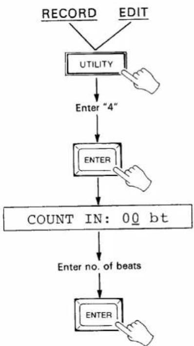
RECORDING WITH A COUNT-IN
Frequently, a click track will have a one-bar count-in which you do not want to record as tempo data. The UTILITY mode COUNT IN function allows you to specify a count-in of any number of beats for the first two tempo recording methods described above.
- From the RECORD or EDIT mode (press the RECORD or EDIT key) press the UTILITY key, enter "4" via the 10-key pad and press ENTER.
- Enter the desired number of beats for the count-in via the 10-key pad or by using the YES> and <NO keys.
- Press ENTER to exit.
- Press the STOP key to exit and cancel at any stage before the last step is performed.
flowchart
graph TD
    A["RECORD"] --> B["UTILITY"]
    C["EDIT"] --> B
    B --> D["Enter "4""]
    D --> E["ENTER"]
    E --> F["COUNT IN: 00 bt"]
    F --> G["Enter no. of beats"]
    G --> H["ENTER"]
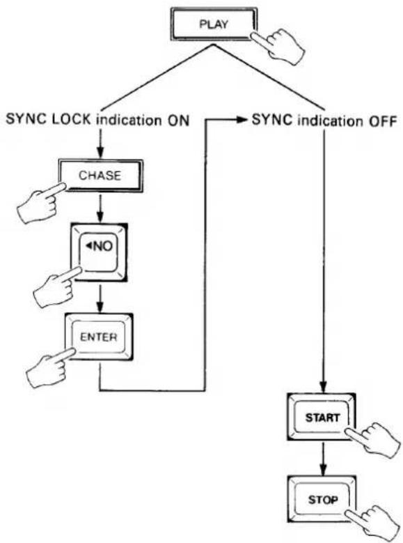
4: PLAYBACK
Two modes of playback are available: non-sync and chase. In the former case, playback is based on internally generated time code and can be used for rehearsing and refining playback of the recorded tempo data. The second, chase (synchronized) mode, is used to synchronize the MSS1 to audio or video tape playback.
NON-SYNC PLAYBACK
- Press the PLAY key to enter the PLAY mode.
- If the SYNC LOCK indicator is lit, press the CHASE key, press the NO key to select
, then press ENTER to set the CHASE mode OFF and return to the PLAY mode. The SYNC LOCK indicator should now be out. - Press the START key. The internal time code generator will begin running and the current time will be displayed on the TIME CODE LED display. The programmed MIDI tempo data will be transmitted via the MIDI OUT terminal in synchronization with the internally generated time code.
- Playback will stop when the end of the recorded tempo data is reached. The STOP key may be pressed to stop playback at any time.
flowchart
graph TD
    A["PLAY"] --> B["SYNC LOCK indication ON"]
    A --> C["SYNC indication OFF"]
    B --> D["CHASE"]
    D --> E["←NO"]
    E --> F["ENTER"]
    F --> G["START"]
    G --> H["STOP"]
    C --> I["START"]
    I --> J["STOP"]
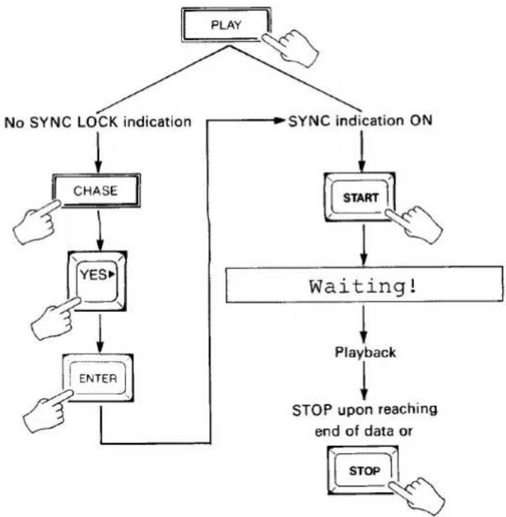
CHASE-MODE SYNCHRONIZED PLAYBACK
- Make sure that the output from the time code track on the recorder is connected to the SMPTE IN terminal on the MSS1.
- Press the PLAY key to enter the PLAY mode.
- If the SYNC LOCK indicator is not lit, press the CHASE key, press the YES key to select
, then press ENTER to set the CHASE mode ON and return to the PLAY mode. The SYNC LOCK indicator should now be lit. -
Press the START key. The SYNC LOCK indicator will go out and the "Waiting!" display will appear on the LCD.
-
Play back the tape from a point a few seconds before the beginning of the music. When the MSS1 locks on to the received time code, the SYNC LOCK indicator will light and the TIME CODE LED display will display the received time code data. The programmed MIDI tempo data will be transmitted via the MIDI OUT terminal in synchronization with the received time code.
-
Playback will stop when the end of the recorded tempo data is reached. The STOP key may be pressed to stop playback at any time.
flowchart
graph TD
    A["PLAY"] --> B["No SYNC LOCK indication"]
    A --> C["SYNC indication ON"]
    B --> D["CHASE"]
    D --> E["YES"]
    E --> F["ENTER"]
    C --> G["START"]
    G --> H["Waiting!"]
    H --> I["Playback"]
    I --> J["STOP upon reaching end of data or STOP"]
STARTING PLAYBACK FROM A SPECIFIED POSITION
The TIME CUE and SONG CUE functions can be used to specify a time-code time or specific measure/beat from which to begin playback. It is also possible to use the YES> and <NO keys to locate a specific time or cue position for playback.
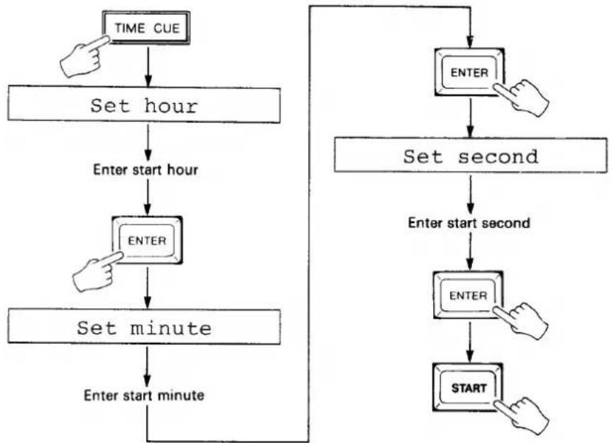
Time Cue
- Press the TIME CUE key.
- Enter the desired start hour via the 10-key pad when the "Set hour" display appears on the LCD, then press ENTER.
- Enter the desired start minute via the 10-key pad when the "Set minute" display appears on the LCD, then press ENTER.
- Enter the desired start second via the 10-key pad when the "Set second" display appears on the LCD, then press ENTER.
- Press the START key to begin playback from the specified time in the non-chase mode. If in the chase mode (SYNC LOCK indicator ON), the "Waiting!" display will appear on the LCD and playback will begin when the time code corresponding to the programmed time cue is received from the tape.
- Press the STOP key to exit and cancel at any stage before the last step is performed.
flowchart
graph TD
    A["TIME CUE"] --> B["Set hour"]
    B --> C["Enter start hour"]
    C --> D["ENTER"]
    D --> E["Set minute"]
    E --> F["Enter start minute"]
    F --> G["ENTER"]
    G --> H["SET second"]
    H --> I["Enter start second"]
    I --> J["ENTER"]
    J --> K["START"]
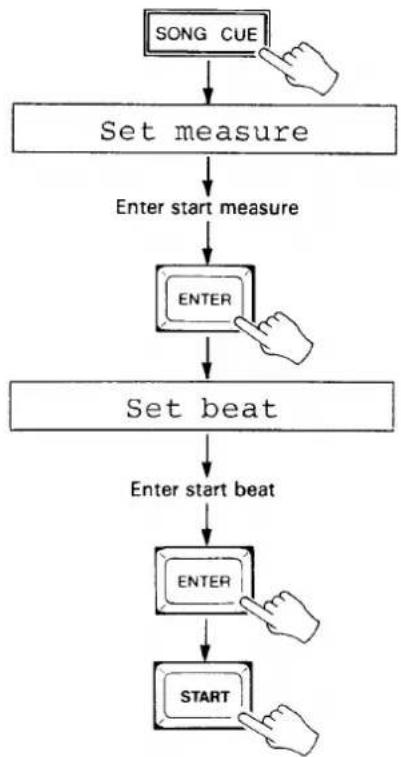
Song Cue
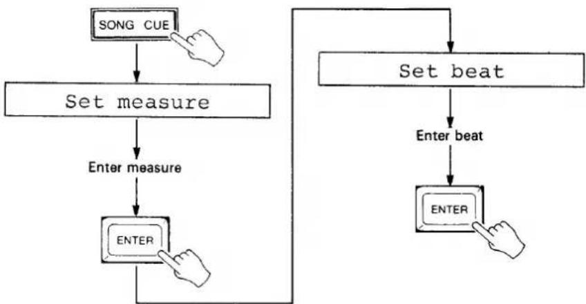
-
Press the SONG CUE key.
-
Enter the desired start measure via the 10-key pad when the "Set measure" display appears on the LCD, then press ENTER.
-
Enter the desired start beat via the 10-key pad when the "Set beat" display appears on the LCD, then press ENTER.
-
Press the START key to begin playback from the specified measure and beat in the non-chase mode. If in the chase mode (SYNC LOCK indicator ON), the "Waiting!" display will appear on the LCD and playback will begin when the time code corresponding to the position of the programmed measure and beat is received from the tape.
- Press the STOP key to exit and cancel at any stage before the last step is performed.
flowchart
graph TD
    A["SONG CUE"] --> B["Set measure"]
    B --> C["Enter start measure"]
    C --> D["ENTER"]
    D --> E["Set beat"]
    E --> F["Enter start beat"]
    F --> G["ENTER"]
    G --> H["START"]
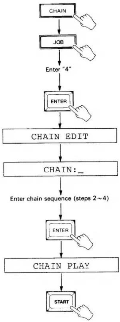
CHAIN EDIT & PLAYBACK
The CHAIN modes permits automatic sequential playback of any or all of the the MSS1's 10 banks, in any order. Before using the CHAIN PLAY function, a chain playback sequence must be set up using the CHAIN EDIT job.
- Press the CHAIN key (the "CHAIN PLAY" display should appear on the LCD), press the JOB key, enter "4" via the 10-key pad and press ENTER. The "CHAIN EDIT" display will appear for a few seconds, and then then "CHAIN:" display.
- The desired chain sequence is entered following the colon (:) in the "CHAIN:" display. The first bank to be played in the chain is entered using the 10-key pad or YES> and <NO keys.
- Move the cursor to the next chain bank location by pressing the START key. The cursor can be moved back one step by pressing the STOP key.
- Continue entering the numbers of the banks to be played in the corresponding sequence -- up to a total of ten steps in the chain. The same bank may be entered twice: e.g. "1 2 3 1."
- Press ENTER to return to the CHAIN PLAY mode.
- Press START to begin chain playback.
flowchart
graph TD
    A["CHAIN"] --> B["JOB"]
    B --> C["Enter "4""]
    C --> D["ENTER"]
    D --> E["CHAIN EDIT"]
    E --> F["CHAIN: _"]
    F --> G["Enter chain sequence (steps 2~4)"]
    G --> H["ENTER"]
    H --> I["CHAIN PLAY"]
    I --> J["START"]
5: EDITING
The MSS1 editing mode makes it possible to make changes to recorded tempo data. You can replace tempo data at specific measure/beats, copy a block of tempo data from any portion of a recorded piece to any other, delete tempo data at specific measure/beats, or insert new tempo data.
LOCATING A SPECIFIED MEASURE/BEAT USING THE SONG CUE FUNCTION
- Press the SONG CUE key.
- Enter the desired measure via the 10-key pad when the "Set measure" display appears on the LCD, then press ENTER.
- Enter the desired beat via the 10-key pad when the "Set beat" display appears on the LCD, then press ENTER.
- Press the STOP key to exit and cancel at any stage before the last step is performed.
flowchart
graph TD
    A["SONG CUE"] --> B["Set measure"]
    B --> C["Enter measure"]
    C --> D["ENTER"]
    D --> E["Set beat"]
    E --> F["Enter beat"]
    F --> G["ENTER"]
    G --> H["Arrow to E"]
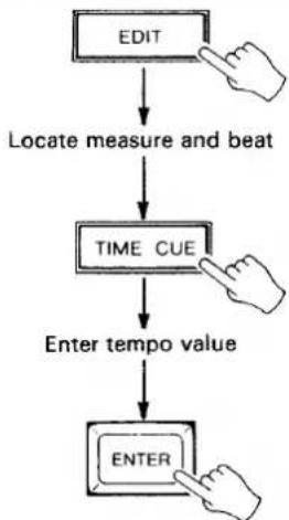
REPLACING TEMPO DATA
- In the EDIT mode (press the EDIT key), use the YES> and <NO keys or the SONG CUE function to locate the measure and beat at which a new tempo value is to be programmed.
- Press the EDIT-REPLACE (TIME CUE) key. The MIDI TEMPO display will go out.
- Enter the new tempo value for the currently displayed location via the 10-key pad or by using the YES> and <NO keys.
- Press the ENTER key.
- Press the STOP key to exit and cancel at any stage before the last step is performed.
flowchart
graph TD
    A["EDIT"] --> B["Locate measure and beat"]
    B --> C["TIME CUE"]
    C --> D["Enter tempo value"]
    D --> E["ENTER"]
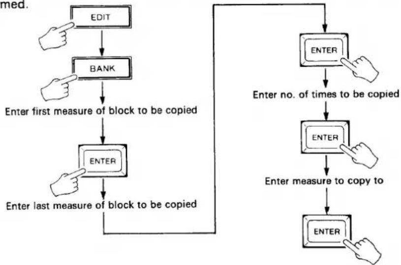
COPYING TEMPO DATA
-
In the EDIT mode (press the EDIT key), press the EDIT-COPY (BANK) key.
-
Enter the number of the measure at the beginning of the block you wish to copy via the 10-key pad or by using the YES> and <NO keys.
-
Press ENTER.
-
Enter the number of the measure at the end of the block you wish to copy via the 10-key pad or by using the YES> and <NO keys.
-
Press ENTER.
-
Enter the number of times you want the specified block to be copied via the 10-key pad or by using the YES> and <NO keys.
-
Press ENTER.
-
Enter the number of the measure to which the specified block is to be copied via the 10-key pad or by using the YES> and <NO keys.
-
Press ENTER.
- Press the STOP key to exit and cancel at any stage before the last step is performed.
flowchart
graph TD
    A["EDIT"] --> B["BANK"]
    B --> C["Enter first measure of block to be copied"]
    C --> D["ENTER"]
    D --> E["Enter last measure of block to be copied"]
    E --> F["ENTER"]
    F --> G["Enter no. of times to be copied"]
    G --> H["ENTER"]
    H --> I["Enter measure to copy to"]
    I --> J["ENTER"]
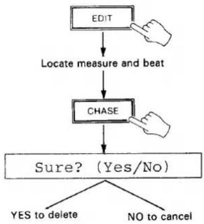
DELETING TEMPO DATA
- In the EDIT mode (press the EDIT key), use the YES> and <NO keys or the SONG CUE function to locate to the measure and beat from which the tempo value is to be deleted.
- Press the EDIT-DELETE (CHASE) key. The "Sure? (Yes/No)" display will appear on the LCD.
- Press the YES key to delete the currently displayed tempo data, or the NO key to cancel.
- All tempo data from the delete location forward is moved back one beat.
- Press the STOP key to exit and cancel at any stage before the last step is performed.
flowchart
graph TD
    A["EDIT"] --> B["Locate measure and beat"]
    B --> C["CHASE"]
    C --> D{Sure? (Yes/No)}
    D -->|YES to delete| E
    D -->|NO to cancel| F
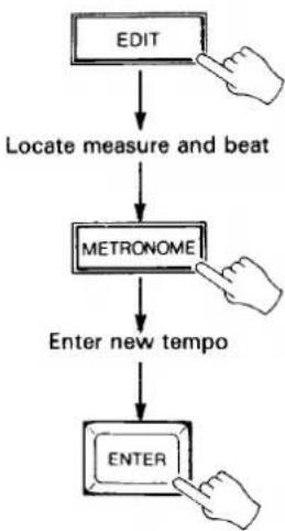
INSERTING TEMPO DATA
- In the EDIT mode (press the EDIT key), use the YES> and <NO keys or the SONG CUE function to locate to the measure and beat at which a new tempo value is to be inserted.
- Press the EDIT-INSERT (METRONOME) key. The MIDI TEMPO display will go out.
- Enter the new tempo value for the currently displayed location via the 10-key pad or by using the YES> and <NO keys.
- Press the ENTER key. All tempo data from the insert location forward is moved up one beat to accommodate the inserted data.
- Press the STOP key to exit and cancel at any stage before the last step is performed.
flowchart
graph TD
    A["EDIT"] --> B["Locate measure and beat"]
    B --> C["METRONOME"]
    C --> D["Enter new tempo"]
    D --> E["ENTER"]
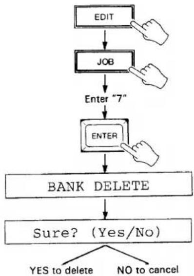
BANK DELETE
This job clears all tempo data from the currently selected bank.
- In the EDIT mode (press the EDIT key), press the JOB key, enter "7" and press ENTER. The "BANK DELETE" message will be displayed on the LCD for a moment, followed by the "Sure? (Yes/No)" message.
- Press the YES key to delete all data from the currently selected bank, or the NO key to cancel.
flowchart
graph TD
    A["EDIT"] --> B["JOB"]
    B --> C["Enter "7""]
    C --> D["ENTER"]
    D --> E["BANK DELETE"]
    E --> F{Sure? (Yes/No)}
    F -->|YES to delete| G
    F -->|NO to cancel| H
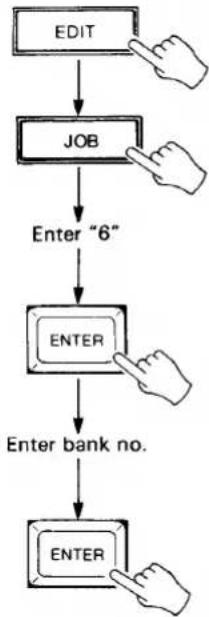
BANK COPY
This job copies all tempo data from the currently selected bank to any other specified bank.
- In the EDIT mode (press the EDIT key), press the JOB key, enter "6" and press ENTER.
- Enter the number of the bank (0 - 9) to which you want to copy the data from the currently selected bank via the 10-key pad or by using the YES> and <NO keys.
- Press ENTER to copy the data and return to the EDIT mode. If the destination bank already contains data, the "Sure?" display will appear. In this case, press YES and the copy operation will be executed.
flowchart
graph TD
    A["EDIT"] --> B["JOB"]
    B --> C["Enter "6""]
    C --> D["ENTER"]
    D --> E["Enter bank no."]
    E --> F["ENTER"]
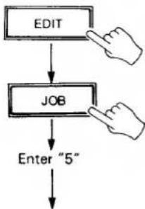
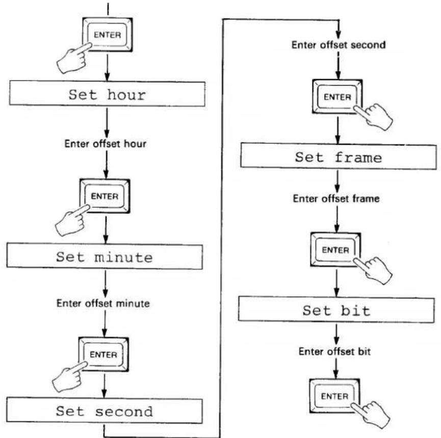
SMPTE OFFSET
The SMPTE OFFSET job makes it possible to offset playback of the recorded tempo data in relation to the received time code by any amount. This is handy for making slight adjustments in the sync timing of the MIDI output, or for re-synchronizing the MIDI data to a newly-recorded SMPTE time code track.
- In the EDIT mode (press the EDIT key), press the JOB key, enter "5" and press ENTER.
- Enter the desired offset hour via the 10-key pad when the "Set hour" display appears on the LCD, then press ENTER.
- Enter the desired offset minute via the 10-key pad when the "Set minute" display appears on the LCD, then press ENTER.
- Enter the desired offset second via the 10-key pad when the "Set second" display appears on the LCD, then press ENTER.
- Enter the desired offset frame via the 10-key pad when the "Set frame" display appears on the LCD, then press ENTER.
- Enter the desired offset bit via the 10-key pad when the "Set bit" display appears on the LCD, then press ENTER.
- Press the STOP key to exit and cancel at any stage before the last step is performed.
flowchart
graph TD
    A["EDIT"] --> B["JOB"]
    B --> C["Enter "5""]
flowchart
graph TD
    A["ENTER"] --> B["Set hour"]
    B --> C["Enter offset hour"]
    C --> D["ENTER"]
    D --> E["Set minute"]
    E --> F["Enter offset minute"]
    F --> G["ENTER"]
    G --> H["Set second"]
    H --> I["Enter offset second"]
    I --> J["ENTER"]
    J --> K["Set frame"]
    K --> L["Enter offset frame"]
    L --> M["ENTER"]
    M --> N["Set bit"]
    N --> O["Enter offset bit"]
    O --> P["ENTER"]
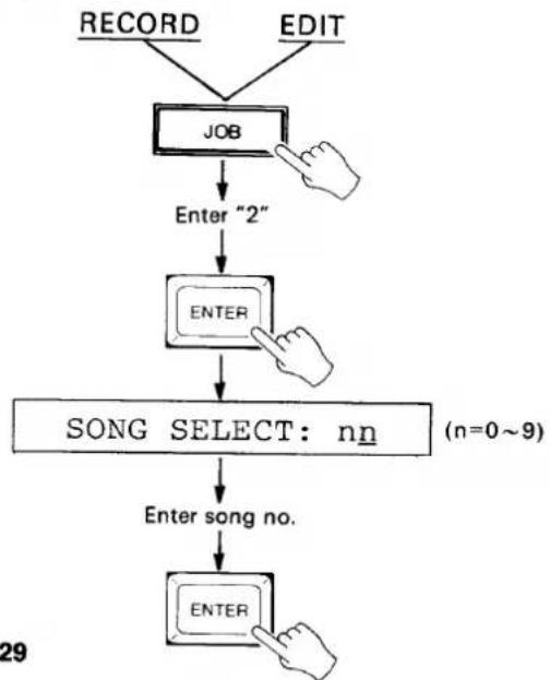
SONG SELECT
This function sets the MSS1 to transmit a MIDI song number between 0 and 99, or none (off), to select the appropriate "song" on the synchronized MIDI sequencer, rhythm programmer or other device. A different song number can be set for each bank so that the appropriate song in the synchronized MIDI device is automatically recalled when a bank is selected on the MSS1. Not all MIDI devices recognize song number data.
- From the RECORD or EDIT mode: press the JOB key, enter "2" via the 10-key pad, and press ENTER. The "SONG SELECT:n" display will appear.
- Enter the desired song number for the currently selected bank using the 10-key pad or YES> and <NO keys (00-99). Song select can be turned off (no number transmitted) by pressing the
to turn back on. - Press ENTER to set the selected song number and return to the previous mode, or press the STOP key to cancel.
flowchart
graph TD
    A["RECORD"] --> B["JOB"]
    C["EDIT"] --> B
    B --> D["Enter "2""]
    D --> E["ENTER"]
    E --> F["SONG SELECT: nn (n=0~9)"]
    F --> G["Enter song no."]
    G --> H["ENTER"]
6: MIDI EVENT RECORDING, PLAYBACK AND EDITING
Unlike the normal recording and playback modes which deal with synchronizing MIDI timing information to SMPTE time code, the MIDI EVENT mode is used to transmit a sequence of MIDI program change and control change numbers in synchronization with the received time code. This can be used, for example, to synchronize operation of the Yamaha DMP7 Digital Mixing Processor to tape playback.
In the MIDI EVENT mode, each "event" to be transmitted is recorded as a single "STEP" on the MIDI LED display. A total of 1793 steps can be stored in the MSS1's internal memory.
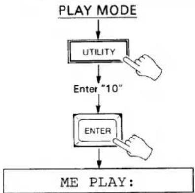
TO SWITCH INTO AND OUT OF THE MIDI EVENT MODE
- From the PLAY mode (press the PLAY key), press the UTILITY key, enter "10" via the 10-key pad and press ENTER.
- The "ME PLAY:" display will appear, followed by the sequence name if programmed, indicating that the MIDI EVENT mode is active.
- Perform step 1 again to switch back to the normal PLAY mode.
flowchart
graph TD
    A["PLAY MODE"] --> B["UTILITY"]
    B --> C["Enter "10""]
    C --> D["ENTER"]
    D --> E["ME PLAY:"]
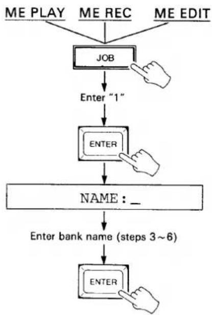
NAMING THE MIDI EVENT SEQUENCE
As with the BANK NAME job, naming the MIDI event sequence is not absolutely necessary but it helps to identify the contents of the sequence.
- From the "ME PLAY", "ME REC" or "ME EDIT" mode (press the RECORD or EDIT key), press the JOB key, enter "1" then press ENTER.
- The "NAME:" display will appear and an underline cursor will appear under the first character position. A down-arrow in the rightmost character position indicates that the lower-case character mode is selected, while an up-arrow indicates the upper-case mode.
- Use the NO and YES keys to select the upper or lower-case character set.
- Enter the first character of the bank name. Each of the numeric entry keys (0 - 9) accesses a number and three characters in sequence, as follows:
| KEY | ACCESSES(Upper-case mode) |
| 0 | 0 A B C |
| 1 | 1 D E F |
| 2 | 2 G H I |
| 3 | 3 J K L |
| 4 | 4 M N O |
| 5 | 5 P Q R |
| 6 | 6 S T U |
| 7 | 7 V W X |
| 8 | 8 Y Z □ (Space) |
| 9 | 9 # & + |
- Move the cursor to the next character position by pressing the START key. The STOP key can be used to move the cursor back to a previous character position.
- Enter the next character and continue until the name is complete.
- Press ENTER to set the name and exit the NAME mode.
flowchart
graph TD
    A["ME PLAY"] --> B["JOB"]
    C["ME REC"] --> B
    D["ME EDIT"] --> B
    B --> E["Enter "1""]
    E --> F["ENTER"]
    F --> G["NAME:_"]
    G --> H["Enter bank name (steps 3~6)"]
    H --> I["ENTER"]
MIDI EVENT SEQUENCE RECORDING METHOD 1 — TIME CODE FROM TAPE OR INTERNAL TIME CODE + MANUAL TAP
With this method it is possible to specify steps in real time while reading the time code track from a tape or using the internally generated time code. Note, however, that in this case the steps are only reserved, and the EDIT mode must then be used to assign program change or control change data to be transmitted at each step.
Time Code from Tape + Manual Tap
- Make sure that the output from the time code track on the recorder is connected to the SMPTE IN terminal on the MSS1.
- Press the RECORD key to enter the ME REC mode.
- If the SYNC LOCK indicator is not lit, press the CHASE key, press the YES key to select
, then press ENTER to set the CHASE mode ON and return to the ME REC mode. The SYNC LOCK indicator should now be lit. - Press the START key. The SYNC LOCK indicator will go out and the "Waiting!" display will appear on the LCD.
- Play back the tape from a point just before the beginning of the piece to be recorded. When the MSS1 locks on to the received time code, the SYNC LOCK indicator will light and the TIME CODE LED display will display the received time code data.
- Tap the START key at each point you want to program an event transmission. Tap-enter the steps required for the entire length of the piece to be recorded. The MIDI STEP display will follow accordingly. Recording is stopped automatically when the memory display on the LCD reaches 0000.
- When the steps for the entire piece have been "tapped in," press the MSS1 STOP key to automatically exit the ME REC mode and enter the ME PLAY mode. Stop and rewind the tape recorder.
- Use the ME EDIT mode REPLACE function to assign event data to the programmed steps (see "EDITING A MIDI EVENT SEQUENCE, Event Replace" on page 35).
flowchart
graph TD
    A["RECORD"] --> B["No SYNC LOCK indication"]
    A --> C["SYNC LOCK indication ON"]
    B --> D["CHASE"]
    D --> E["YES"]
    E --> F["ENTER"]
    C --> G["START"]
    G --> H["Waiting!"]
    H --> I["Playback"]
    I --> J["TAP IN"]
    J --> K["STOP"]
Internal Time Code + Manual Tap
- Press the RECORD key to enter the ME REC mode.
- If the SYNC LOCK indicator is lit, press the CHASE key, press the NO key to select
, then press ENTER to set the CHASE mode OFF and return to the ME REC mode. The SYNC LOCK indicator should now be out. - Press the START key. The internal time code generator will begin running and the time code will be displayed on the TIME CODE LED display.
- Tap the START key at each point you want to program an event transmission. Tap-enter the steps required for the entire length of the piece to be recorded. The MIDI STEP display will follow accordingly. Recording is stopped automatically when the memory display on the LCD reaches 0000.
- When the steps for the entire piece have been "tapped in," press the MSS1 STOP key to automatically exit the ME REC mode and enter the ME PLAY mode. Stop and rewind the tape recorder.
- Use the ME EDIT mode REPLACE function to assign event data to the programmed steps (see "EDITING A MIDI EVENT SEQUENCE, Event Replace" on page 35).
flowchart
graph TD
    A["RECORD"] --> B["SYNC LOCK indication ON"]
    B --> C["CHASE"]
    C --> D["<NO"]
    D --> E["ENTER"]
    E --> F["START"]
    F --> G["TAP IN"]
    G --> H["STOP"]
    H --> I["->"]
    I --> J["->"]
    J --> K["->"]
    K --> L["->"]
    L --> M["->"]
    M --> N["->"]
    N --> O["->"]
    O --> P["->"]
    P --> Q["->"]
    Q --> R["->"]
    R --> S["->"]
    S --> T["->"]
    T --> U["->"]
    U --> V["->"]
    V --> W["->"]
    W --> X["->"]
    X --> Y["->"]
    Y --> Z["->"]
    Z --> A
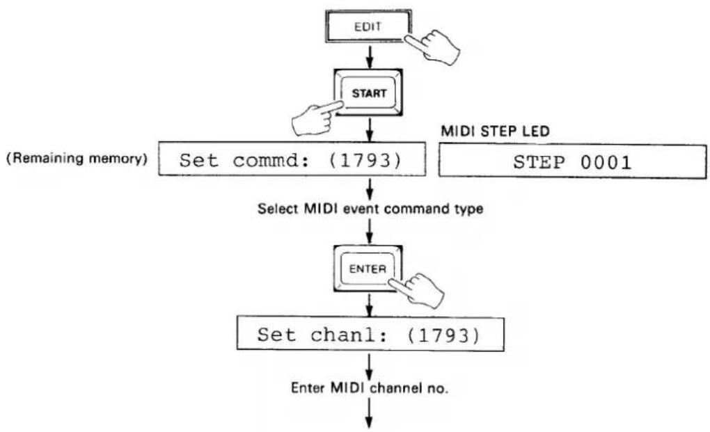
MIDI EVENT SEQUENCE RECORDING METHOD 2 — STEP RECORDING
This method will only work if no data has been previously recorded.
- Press the EDIT key to enter the ME EDIT mode.
- Press the START key. The "Set commd:(1793)" display will appear on the LCD and STEP 0001 will be displayed on the MIDI STEP LED display.
- Select the desired MIDI event command type using the YES> and <NO keys. A □ on the MIDI COMMAND LED display defines a program change command, while a C defines a control change command.
- Press ENTER and the "Set chanl:" display will appear on the LCD.
- Enter the number of the MIDI channel on which the command for the current step is to be transmitted (1 through 16) via the 10-key pad or by using the YES> and <NO keys. A setting of "00" inhibits transmission of the command.
- Press ENTER and the "Set data1:" display will appear on the LCD.
- Enter the value of the first data byte of the command via the 10-key pad or by using the YES> and <NO keys.
- Press ENTER and, if a control change command was selected, the "Set data2:" display will appear on the LCD. If a program change command was selected skip to step 11.
- Enter the value of the second data byte of the command via the 10-key pad or by using the YES> and <NO keys.
- Press ENTER and the "Set hour" display will appear on the LCD.
- Enter the hour at which the command is to be transmitted via the 10-key pad, then press ENTER.
- Enter the minute at which the command is to be transmitted via the 10-key pad when the "Set minute" display appears on the LCD, then press ENTER.
- Enter the second at which the command is to be transmitted via the 10-key pad when the "Set second" display appears on the LCD, then press ENTER.
- Enter the frame at which the command is to be transmitted when the "Set frame" display appears on the LCD, then press ENTER.
- Enter the bit at which the command is to be transmitted when the "Set bit" display appears on the LCD, then press ENTER.
- The STEP display is automatically advanced to the next step number. Go back to step 3, above, to enter the next step.
- When the required number of steps have been entered, press the STOP key to exit the step recording mode and return to the ME EDIT mode.
flowchart
graph TD
    A["EDIT"] --> B["START"]
    B --> C["Set commd: (1793)"]
    C --> D["Select MIDI event command type"]
    D --> E["ENTER"]
    E --> F["Set chanl: (1793)"]
    F --> G["Enter MIDI channel no."]
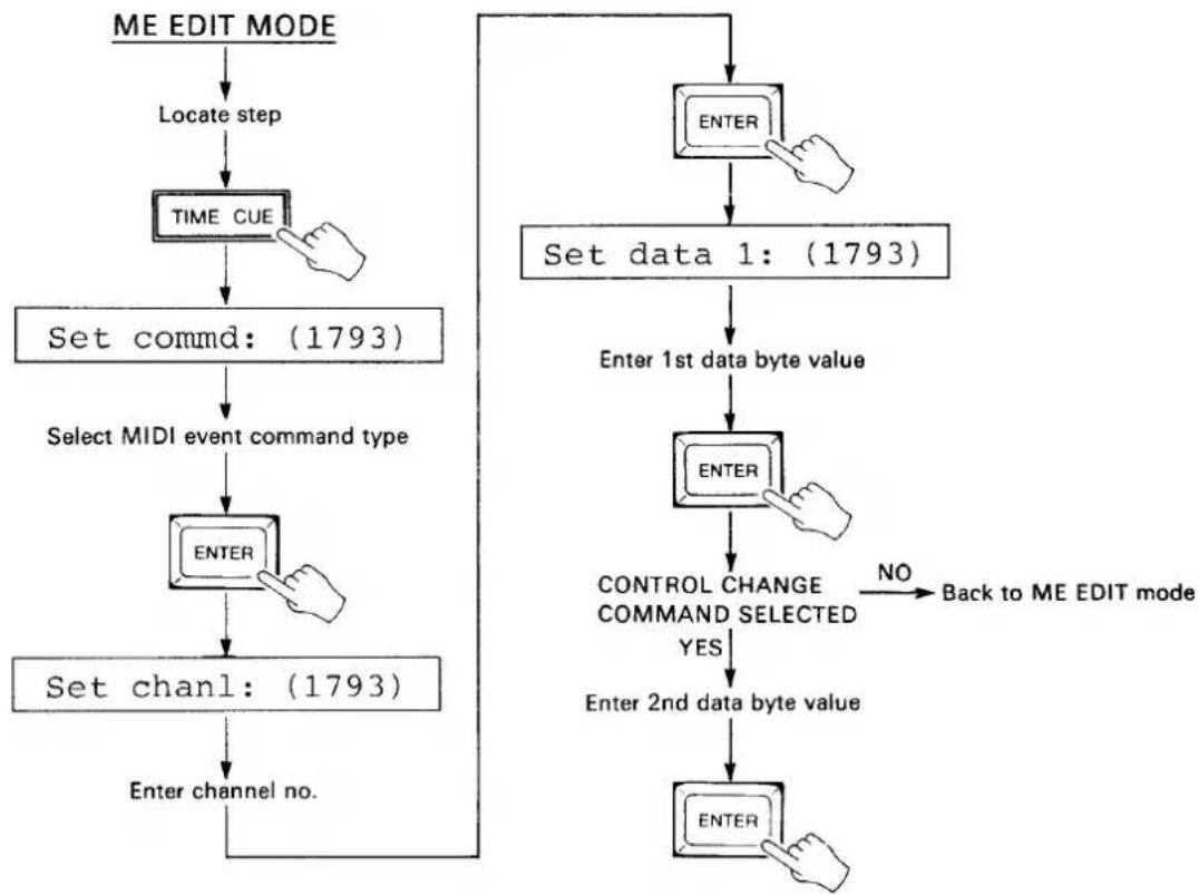
Event Replace
- In the ME EDIT mode (press the EDIT key), use the YES> and <NO keys or the STEP CUE function to locate the step at which new data is to be programmed.
- Press the EDIT-REPLACE (TIME CUE) key. The MIDI COMMAND, CHANNEL and DATA displays will go out. The "Set commd:(1793)" display will appear on the LCD.
- Select the desired MIDI event command type using the YES and NO keys. A ☐ on the MIDI COMMAND LED display defines a program change command, while a ☐ defines a control change command.
- Press ENTER and the "Set chanl:" display will appear on the LCD.
- Enter the number of the MIDI channel on which the command for the current step is to be transmitted (1 through 16) via the 10-key pad or by using the YES> and <NO keys. A setting of "00" inhibits transmission of the command.
- Press ENTER and the "Set data1:" display will appear on the LCD.
- Enter the value of the first data byte of the command via the 10-key pad or by using the YES> and <NO keys.
- Press ENTER and, if a control change command was selected, the "Set data2:" display will appear on the LCD. If a program change command was selected the MSS1 returns to the ME EDIT mode.
- Enter the value of the second data byte of the command via the 10-key pad or by using the YES> and <NO keys.
- Press ENTER to return to the ME EDIT mode.
- Press the STOP key to exit and cancel at any stage before the last step is performed.
flowchart
graph TD
    A["ME EDIT MODE"] --> B["Locate step"]
    B --> C["TIME CUE"]
    C --> D["Set commd: (1793)"]
    D --> E["Select MIDI event command type"]
    E --> F["ENTER"]
    F --> G["Set chanl: (1793)"]
    G --> H["Enter channel no."]
    H --> I["ENTER"]
    I --> J["Set data 1: (1793)"]
    J --> K["Enter 1st data byte value"]
    K --> L["ENTER"]
    L --> M["CONTROL CHANGE COMMAND SELECTED YES"]
    M --> N["Enter 2nd data byte value"]
    N --> O["ENTER"]
    O --> P["NO Back to ME EDIT mode"]
Event Delete
-
In the ME EDIT mode (press the EDIT key), use the YES> and <NO keys or the STEP CUE function to locate the step to be deleted.
-
Press the EDIT-DELETE (CHASE) key. The "Sure? (Yes/No)" display will appear on the LCD.
-
Press the YES key to delete the currently displayed step, or the NO key to cancel.
- Press the STOP key to exit and cancel at any stage before the last step is performed.
flowchart
graph TD
    A["ME EDIT MODE"] --> B["Locate step"]
    B --> C["CHASE"]
    C --> D{Sure? (Yes/No)}
    D -->|YES to delete| E
    D -->|NO to cancel| F
Event Insert
-
In the ME EDIT mode, press the EDIT-INSERT (METRONOME) key. The MIDI COMMAND, CHANNEL and DATA displays will go out. The "Set commd:(1793)" display will appear on the LCD.
-
Select the desired MIDI event command type using the YES and NO keys. A ☐ on the MIDI COMMAND LED display defines a program change command, while a ☐ defines a control change command.
-
Press ENTER and the "Set chanl:" display will appear on the LCD.
-
Enter the number of the MIDI channel on which the command for the current step is to be transmitted (1 through 16) via the 10-key pad or by using the YES> and <NO keys. A setting of "00" inhibits transmission of the command.
-
Press ENTER and the "Set data1:" display will appear on the LCD.
-
Enter the value of the first data byte of the command via the 10-key pad or by using the YES> and <NO keys.
-
Press ENTER and, if a control change command was selected, the "Set data2:" display will appear on the LCD. If a program change command was selected skip to step 11.
-
Enter the value of the second data byte of the command via the 10-key pad or by using the YES> and <NO keys.
-
Press ENTER and the "Set hour" display will appear on the LCD.
-
Enter the hour at which the command is to be transmitted via the 10-key pad, then press ENTER.
-
Enter the minute at which the command is to be transmitted via the 10-key pad when the "Set minute" display appears on the LCD, then press ENTER.
-
Enter the second at which the command is to be transmitted via the 10-key pad when the "Set second" display appears on the LCD, then press ENTER.
-
Enter the frame at which the command is to be transmitted when the "Set frame" display appears on the LCD, then press ENTER.
-
Enter the bit at which the command is to be transmitted when the "Set bit" display appears on the LCD, then press ENTER. The INSERT mode is exited and the ME EDIT mode is automatically re-entered.
- Press the STOP key to exit and cancel at any stage before the last step is performed.
7: EXTERNAL DATA STORAGE AND RETRIEVAL
These functions permit storing the internal BANK (0 through 9) and MIDI EVENT SEQUENCE data on an external Yamaha RAM4 Data Cartridge. RAM4 Data Cartridges are available from your Yamaha dealer.
The BULK OUT function permits dumping the same data via the MIDI OUT terminal, so it can be stored on a MIDI data recorder or similar storage device.
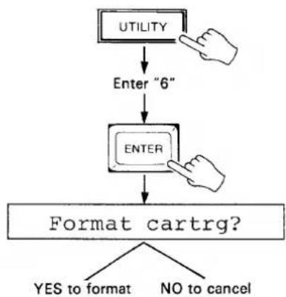
FORMATTING A NEW RAM4 DATA CARTRIDGE
New RAM4 cartridges MUST be formatted by the MSS1 before they can be used to store MSS1 data.
- Make sure the RAM4 cartridge memory protect switch is turned OFF, and the cartridge is properly inserted into the MSS1 cartridge slot.
- Press the UTILITY key, enter "6" via the 10-key pad, and press ENTER.
-
In response to the "Format cartrg?" display on the LCD, press the YES key to format the cartridge or the NO key to cancel.
-
If you attempt to format a cartridge on the which the memory protect switch is set to ON, the "Cartrg protected" display will appear and the format operation will be canceled.
- If you attempt to format a cartridge of the wrong type, the "Cartrg other typ" display will appear and the format operation will be canceled.
- If you attempt to run the format job when no cartridge is inserted, the "Cartrg not ready" display will appear and the format operation will be canceled.
flowchart
graph TD
    A["UTILITY"] --> B["Enter "6""]
    B --> C["ENTER"]
    C --> D["Format cartrg?"]
    D --> E{YES to format}
    D --> F{NO to cancel}
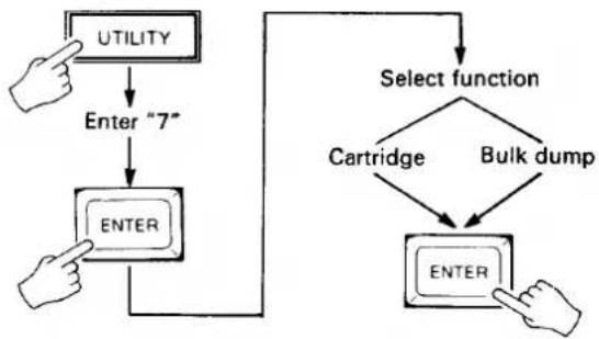
SAVE TO CARTRIDGE OR MIDI BULK DUMP
This job accesses both the cartridge save and MIDI bulk dump functions.
- Make sure that a properly formatted cartridge is used, that the RAM4 cartridge memory protect switch is turned OFF, and the cartridge is properly inserted into the MSS1 cartridge slot.
- Press the UTILITY key, enter "7" via the 10-key pad, and press ENTER.
- Use the YES> and <NO keys to select either the "Cartridge?" or "Bulk dump?" function.
- Press ENTER to execute the selected operation.
- The LCD display will display "Executing!" while saving to cartridge, or "Transmitting" while performing a bulk dump.
-
If you attempt to save to a cartridge on the which the memory protect switch is set to ON, the "Cartrg protected" display will appear and the save operation will be canceled.
-
If you attempt to save to a cartridge of the wrong type, the "Cartrg other typ" display will appear and the save operation will be canceled.
- If you attempt to run the save job when no cartridge is inserted, the "Cartrg not ready" display will appear and the save operation will be canceled.
- If you attempt to save to a cartridge which has not been properly formatted by the MSS1, the "Format conflict" display will appear and the save operation will be canceled.
- If a verify error occurs during the save operation, the ">I/O Error!<" message will appear and the save operation will be canceled.
flowchart
graph TD
    A["UTILITY"] --> B["Enter "7""]
    B --> C["ENTER"]
    C --> D["Select function"]
    D --> E["Cartridge"]
    D --> F["Bulk dump"]
    E --> G["ENTER"]
    F --> G
LOAD FROM CARTRIDGE OR RECEIVE BULK DUMP
This job accesses both the cartridge load and MIDI bulk dump receive functions.
- Make sure that a properly formatted cartridge is used, and the cartridge is properly inserted into the MSS1 cartridge slot.
- Press the UTILITY key, enter "8" via the 10-key pad, and press ENTER.
- Use the YES> and <NO keys to select either the "Cartridge?" or "Bulk dump?" function.
- Press ENTER to execute the selected operation.
- The LCD display will display "Executing!" while loading or receiving a bulk dump.
- If you attempt to load from a cartridge of the wrong type, the "Cartrg other typ" display will appear and the load operation will be canceled.
- If you attempt to run the load job when no cartridge is inserted, the "Cartrg not ready" display will appear and the load operation will be canceled.
- If you attempt to load from a cartridge which has not been properly formatted by the MSS1, the "Format conflict" display will appear and the load operation will be canceled.
- If a verify error occurs during the load operation, the "I/O Error!" message will appear and the load operation will be canceled.

flowchart
graph TD
    A["UTILITY"] --> B["Enter "8""]
    B --> C["ENTER"]
    C --> D["Select function"]
    D --> E["Cartridge"]
    D --> F["Bulk dump"]
    E --> G["ENTER"]
    F --> G
    G --> H["Executing!"]
8: OTHER FUNCTIONS
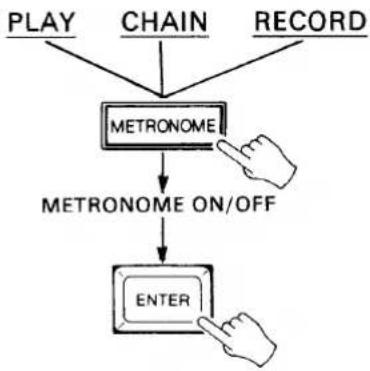
METRONOME
The metronome function turns audible output of the MSS1's internal metronome ON or OFF.
- From the PLAY, RECORD or CHAIN mode press the METRONOME key.
- Use the YES> and <NO keys to turn the metronome ON or OFF.
- Press ENTER
flowchart
graph TD
    A["PLAY"] --> C["METRONOME"]
    B["CHAIN"] --> C
    D["RECORD"] --> C
    C --> E["METRONOME ON/OFF"]
    E --> F["ENTER"]
TOTAL TIME
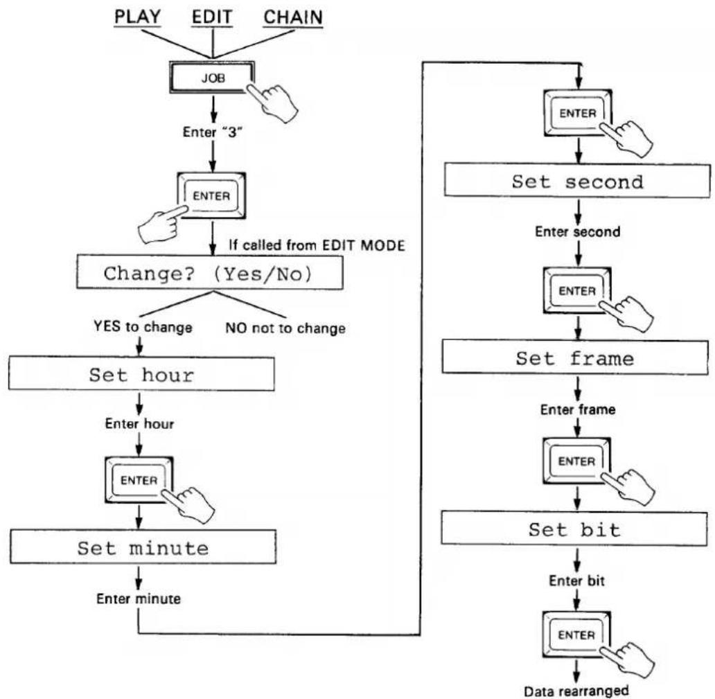
This job displays the total time of the recorded tempo data in the currently selected bank, and allows modifying the total time of the recorded data.
- From the PLAY, EDIT or CHAIN mode, press the JOB key, enter "3" and press ENTER.
- The total time will be displayed on the TIME CODE display and, if called from the EDIT mode, the "Change? (Yes/No)" display will appear on the LCD.
- Press
to program a new total time. - If you pressed YES>, the MSS1 will prompt you for the new time in hours: "Set hour." Enter the desired total time hour via the 10-key pad when the "Set hour" display appears on the LCD, then press ENTER.
- Enter the desired total time minute via the 10-key pad when the "Set minute" display appears on the LCD, then press ENTER.
- Enter the desired total time second via the 10-key pad when the "Set second" display appears on the LCD, then press ENTER.
- Enter the desired total time frame via the 10-key pad when the "Set frame" display appears on the LCD, then press ENTER.
- Enter the desired total time bit via the 10-key pad when the "Set bit" display appears on the LCD, then press ENTER.
The MSS1 will then rearrange the data to fit within the new total time. If, for example, the original total time was 1 minute at a tempo of 120 and you enter a new total time of 2 minutes, the tempo will be changed to 60 and the data transmitted accordingly.
- The MSS1 tempo range is from 20 to 275. Total time settings that would create a tempo outside this range will be ignored.
- Press the STOP key to exit and cancel at any stage before the last step is performed.
flowchart
graph TD
    A["PLAY"] --> B["JOB"]
    C["EDIT"] --> B
    D["CHAIN"] --> B
    B --> E["Enter "3""]
    E --> F["ENTER"]
    F --> G["If called from EDIT MODE"]
    G --> H["Change? (Yes/No)"]
    H --> I{YES to change}
    H --> J{NO not to change}
    I --> K["Set hour"]
    K --> L["Enter hour"]
    L --> M["ENTER"]
    M --> N["Set minute"]
    N --> O["Enter minute"]
    P["ENTER"] --> Q["Set second"]
    Q --> R["Enter second"]
    R --> S["SET frame"]
    S --> T["Enter frame"]
    T --> U["ENTER"]
    U --> V["Set bit"]
    V --> W["Enter bit"]
    W --> X["ENTER"]
    X --> Y["Data rearranged"]
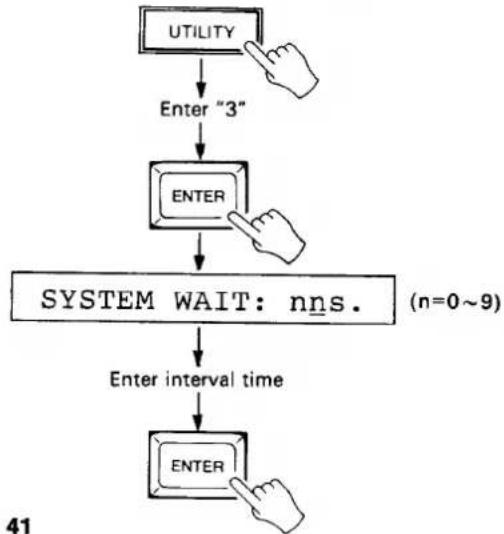
INTERVAL TIME
This job eliminates lock start-up errors caused by the time required for some MIDI devices to compute the start point using the received MIDI song position pointer. Specifically, the INTERVAL TIME job sets the interval between transmission of the song position pointer and the MIDI start message. Interval range is from 0.1 to 59 seconds.
- Press the UTILITY key, enter "3" via the 10-key pad and press ENTER. The "SYSTEM WAIT:nns" display will appear.
- Enter the desired interval time using the 10-key pad or YES> and <NO keys.
- Press ENTER.
flowchart
graph TD
    A["UTILITY"] --> B["Enter "3""]
    B --> C["ENTER"]
    C --> D["SYSTEM WAIT: nns. (n=0~9)"]
    D --> E["Enter interval time"]
    E --> F["ENTER"]
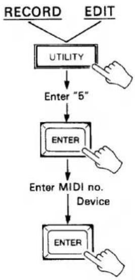
DEVICE NUMBER
This job sets the MIDI device number of the MSS1.
- From the RECORD or EDIT mode, press the UTILITY key, enter "5" and press ENTER.
- Enter the desired MIDI device number via the 10-key pad or by using the YES> and <NO keys. Available device numbers a 1 through 16, with the "all" setting enabling the MSS1 on all device numbers.
flowchart
graph TD
    A["RECORD"] --> B["UTILITY"]
    C["EDIT"] --> B
    B --> D["Enter "5""]
    D --> E["ENTER"]
    E --> F["Enter MIDI no. Device"]
    F --> G["ENTER"]
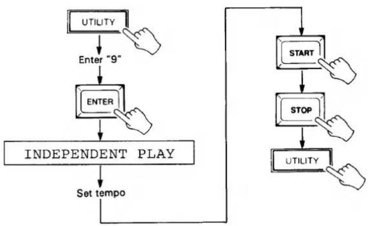
INDEPENDENT PLAY
This job sets the MSS1 to output MIDI data timing data at any specified tempo.
- Press the UTILITY key, enter "9" via the 10-key pad and press ENTER. The "INDEPENDENT PLAY" display will appear on the LCD, and all LED digits except the TEMPO display will go out.
- Set the desired tempo using the 10-key pad or YES> and <NO keys.
- Press START to begin transmitting MIDI timing data via the MIDI OUT terminals at the selected tempo. The tempo may be varied as described in step 2 while in the RUN mode.
- Press the STOP key to stop transmission of MIDI timing data. The STOP key can be pressed again to continue transmission of MIDI timing data.
- Press the UTILITY key to exit from the INDEPENDENT PLAY mode.
● The tempo can be changed at any time by entering the desired tempo using the 10-key pad and pressing ENTER.
flowchart
graph TD
    A["UTILITY"] --> B["Enter "9""]
    B --> C["ENTER"]
    C --> D["INDEPENDENT PLAY"]
    D --> E["Set tempo"]
    E --> F["START"]
    F --> G["STOP"]
    G --> H["UTILITY"]
9: MSS1 SPECIFICATIONS
Synchronization.... MIDI clock signal to SMPTE time code (30, 30 drop-frame, 25, 24 fps).
Memory.... 16 k-bytes, lithium battery backup.
Max. 150 tempo change points.
Max. 1793 program/control change points.
Max. memory (7178 beats, 7168 in one bank) @ tempo 120, 4/4: approx. 60 minutes.
Connectors.... CLICK IN, SMPTE IN, SMPTE OUT, METRONOME OUT, FOOT SW IN, MIDI IN, MIDI OUT (x2), RAM CARTRIDGE.
Keys.... PLAY, RECORD, EDIT, CHAIN, GENERATOR, UTILITY, JOB, SONG CUE, TIME CUE, BANK SELECT, CHASE, METRONOME, INC, DEC, ENTER, STOP, START, 10-key numeric pad.
Variable Control..... Click input level control.
LEDs SYNC, METRONOME, RUN, 7-segment x 20
LCD 16 characters x 1 line, backlit.
SMPTE IN -24 dBm \~ +4 dBm
Generator out .... -10 dBm ±2 dBm
Metronome out....-11 dBm ±2 dBm
Click in -20 dBm \~ +4
Power Requirements..... U.S. & Canada: 120 V AC 50/60 Hz, 15 W
General Model: 220 \~ 240 V AC 50/60 Hz, 15 W
Dimensions (W x H x D) 439 x 73.5 x 286 mm
Weight 3.8 kg.
Accessories...... MIDI cable x 1
RCA phone plug adapters x 2
MSS1 MIDI DATA
1. APPLICABILITY
2. #8978 EXCLUSIVE MESSAGE
The following data applies specifically to the MSS1.
2-1. BULK DUMP FORMAT
| bin | hex | description |
| 11110000 | F0 | MIDI STATUS BYTE (SYSTEM EXCLUSIVE) |
| 01000011 | 43 | YAMAHA ID NUMBER |
| 0000nnnn | 0n | SUB STATUS=0, DEVICE NUMBER=n |
| 01111110 | 7E | FORMAT NUMBER=7E (UNIVERSAL BULK DUMP) |
| 0bbbbbbb | BYTE COUNT (H) | |
| 0bbbbbbb | BYTE COUNT (L) | |
| 01001100 | 4C (L) | HEADER (CLASSIFICATION NAME) "LM " |
| 01001101 | 4D (M) | |
| 00100000 | 20 ( ) | |
| 00100000 | 20 ( ) | |
| 00111000 | 38 (8) | (DATA FORMAT NAME) "8978 " |
| 00111001 | 39 (9) | |
| 00110111 | 37 (7) | |
| 00111000 | 38 (8) | |
| 00100000 | 20 ( ) | |
| 00100000 | 20 ( ) | |
| 0ddddddd | SYM INTERNAL DATA | |
| : | ||
| 0ddddddd | ||
| 0eeeeeee | CHECK SUM | |
| 11110111 | F7 | END OF EXCLUSIVE |
- The byte count represents the total number of bytes in the header and internal data.
- The checksum is the lower seven bits of the sum of the 2's complement of the header and internal data.
- The internal data is in ASCII form. (The most significant and least significant 4 bits of the binary data are separated and converted to ASCII.)
- When the data is transmitted, the internal data is divided up so that the byte count will be less than 4096. A byte count, header and checksum are added to each block. An interval of more than 100 milliseconds is provided between transmission of each block. "EOX" is transmitted after all blocks have been transmitted.
● Transmission from the MSS1 consists of eight 3594 byte counts. One 2236 byte count is transmitted last.
● The DEVICE NUMBER is set via the MSS1 DEVICE NUMBER utility function.
2-2. DUMP REQUEST FORMAT
| bin | hex | description |
| 11110000 | F0 | MIDI STATUS BYTE (SYSTEM EXCLUSIVE) |
| 01000011 | 43 | YAMAHA ID NUMBER |
| 0010nnnn | 2n | SUB STATUS=2, DEVICE NUMBER=n |
| 01111110 | 7E | FORMAT NUMBER=7E |
| 11110111 | F7 | END OF EXCLUSIVE |
● Not recognized when the MSS1 is operating.
- TRANSMITTED DATA
3-1.
| bin | hex | description |
| 11111000 | F8 | TIMING CLOCK |
| 11111010 | FA | START |
| 11111011 | FB | CONTINUE |
| 11111100 | FC | STOP |
| 11110010 | F2 | SONG POSITION POINTER |
| 01111111 | 1111111: (LEAST SIGNIFICANT) | |
| 0hhhhhhh | hhhhhhh: (MOST SIGNIFICANT) | |
| 11110011 | F3 | SONG SELECT |
| 0sssssss | sssssss: (song #) |
● The above MIDI message is transmitted in the PLAY or CHAIN PLAY mode.
● The SONG SELECT number is entered using the MSS1 SONG SELECT job.
● The SONG SELECT default is OFF.
3-2.
| bin | hex | description |
| 1011nnnn | Bn | CONTROL CHANGE |
| 0cccccccc | cccccccc: (CONTROL #) | |
| 0vvvvvvv | vvvvvvv: (CONTROL VALUE) | |
| nnnn: (CHANNEL #) | ||
| 1100nnnn | Cn | PROGRAM CHANGE |
| 0ppppppp | ppppppp: (PROGRAM NUMBER) | |
| nnnn: (CHANNEL #) |
- The above MIDI message is transmitted in the MIDI EVENT PLAY/MIDI EVENT EDIT mode.
- The channel number, control number, control value and program number are entered via the MSS1 front panel.
- The MSS1 will only recognize a DUMP REQUEST when it is not currently performing any other operation.
- EXCLUSIVE DATA is only recognized when the MSS1 is in the DATA LOAD READY state.
● The MSS1 will not recognize data in any other mode.
4. DATA RECOGNITION
- TRANSFERRED RECEIVE DATA
| bin | hex | description |
| 111100000nnnnnnn⋮ | F0 | SYSTEM EXCLUSIVE MESSAGE |
| 11110111 | F7 | END OF EXCLUSIVE MESSAGE |
| 11110110 | F6 | TUNE REQUEST |
| 1011nnnn0cccccccc0vvvvvvv | Bn | MODE MESSAGE |
| 1000nnnn0kkkkkkk0vvvvvvv | 8n | NOTE OFF |
| 1001nnnn0kkkkkkk0vvvvvvv | 9n | NOTE ON |
| 1010nnnn0kkkkkkk0vvvvvvv | An | POLYPHONIC KEY PRESSURE |
| 1011nnnn0cccccccc0vvvvvvv | Bn | CONTROL CHANGE |
| 1100nnnn0ppppppp | Cn | PROGRAM CHANGE |
| 1101nnnn0vvvvvvv | Dn | CHANNEL PRESSURE |
| 1110nnnn0vvvvvvv0vvvvvvv | $En | PITCH BENDER CHANGE |
- No data is transmitted when the MSS1 is in the GENERATOR or RECORD mode.
| Function ... | Transmitted | Recognized | Remarks | |
| Basic Channel | Default Changed | x | x | |
| x | x | |||
| Mode | Default Messages Altered | x | x | X1 |
| x | x | |||
| XXXXXXXXXXXXXX | x | |||
| Note Number : True voice | x | x | X1 | |
| XXXXXXXXXXXXXX | x | |||
| Velocity Note ON Note OFF | x | x | X1 | |
| x | x | X1 | ||
| After Touch | Key's Ch's | x | x | X1 |
| x | x | X1 | ||
| Pitch Bender | x | x | X1 | |
| ∅ - 121 | o | x | X1 in MIDI event play mode | |
| Control | ||||
| Change | ||||
| Prog Change : True # | oXXXXXXXXXXXXXX | x | X1 in MIDI event play mode | |
| XXXXXXXXXXXXXX | ||||
| System Exclusive | o | o | X2,X1 | |
| System : Song Pos : Song Sel : Common : Tune | o | x | in play or chain play | |
| o | x | |||
| x | x | X1 | ||
| System :Clock : Real Time :Commands | o | X3 | x | |
| o | X3 | x | ||
| Aux :Local ON/OFF : All Notes OFF : Mes- :Active Sense : sages:Reset | x | x | X1 | |
| x | x | X1 | ||
| x | x | |||
| Notes: X1 = Excluding generator or record mode, these messages are bypassed to MIDI OUT. X2 = Dump request is not recognized when machine is running. Bulk data is received in data load mode. X3 = Messages are not transmitted in generator or record mode. | ||||
SINCE 1887

YAMAHA
HAMAMATSU, JAPAN