8200X7 - Hi-Fi-System Audiolab - Kostenlose Bedienungsanleitung
Finden Sie kostenlos die Bedienungsanleitung des Geräts 8200X7 Audiolab als PDF.


Benutzerfragen zu 8200X7 Audiolab
0 Frage zu diesem Gerät. Beantworten Sie die, die Sie kennen, oder stellen Sie Ihre eigene.
Eine neue Frage zu diesem Gerät stellen
Laden Sie die Anleitung für Ihr Hi-Fi-System kostenlos im PDF-Format! Finden Sie Ihr Handbuch 8200X7 - Audiolab und nehmen Sie Ihr elektronisches Gerät wieder in die Hand. Auf dieser Seite sind alle Dokumente veröffentlicht, die für die Verwendung Ihres Geräts notwendig sind. 8200X7 von der Marke Audiolab.
BEDIENUNGSANLEITUNG 8200X7 Audiolab
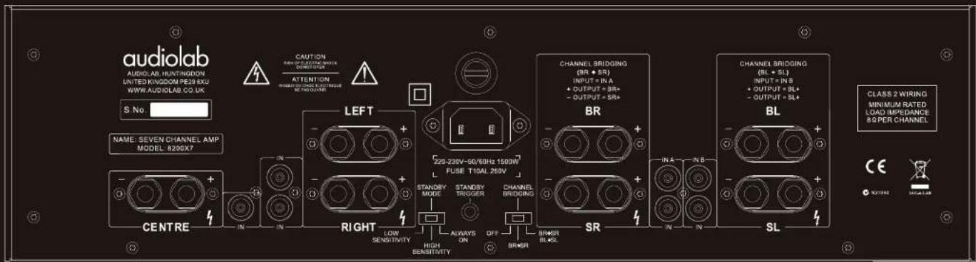
text_image
audiolab AUDIO: AR. HUNTINGON UNITED KINGDOM PER 201 EU WWW.AUDIOLAB CO. UK S No. CAUTION MINIMUM RATED SWITCH OUTDO OUTPUT ATTENTION MINIMUM SWITCH, REFERENCE MECHANICAL LEFT 220-230V-SR/60Hz 1500W FUSE T10AL 250V BR CHANNEL BRIDGING (BL + SL) INPUT = IN A + OUTPUT = SR+ - OUTPUT = SR+ BR CHANNEL BRIDGING (BL + SL) INPUT = IN B + OUTPUT = BL+ - OUTPUT = SL+ BL CLASS 2 WIRING MINIMUM RATED LOAD IMPEFERENCE & PER CHANNEL CENTRE RIGHT LOW SENSITIVITY STANDBY MODE STANDBY TROGER CHANNEL BRIDGING HIGH SENSITIVITY OFF SR+SR SR IN A IN B IN IN SL
text_image
8:00:7。 audielab8200X7
User Instructions
audiolab
9: Warranty
Audiolab limited warranty
Audiolab Ltd. warrants this product, subject to the terms and conditions below, to be free from defects in materials and workmanship. During the warranty period Audiolab will repair or replace (at Audiolab's option) this product, or any defective part in this product, if it is found to be defective due to faulty materials, workmanship or function. The warranty period may vary from country to country.
Terms and conditions:
The warranty starts on the date of purchase (or the date of delivery if this is later).
You must provide proof of purchase / delivery before work can be carried out. Without this proof, any work carried out will be chargeable to you.
All work will be carried out by Audiolab or its authorised agents or distributors. Any unauthorised repair or modification will void this warranty.
If any part is no longer available it will be replaced with a functional part.
Any parts that are replaced will become the property of Audiolab. Any repair or replacement under this warranty will not extend the period of warranty.
This warranty is valid only in the country of purchase, applies only to the first purchaser and is not transferable.
The following are not covered:
- Products on which the serial number has been removed, altered or otherwise made illegible.
• Normal wear and tear and cosmetic damage.
• Transportation or installation of the product. - Accidental damage, faults caused by commercial use, acts of God, incorrect installation, connection or packaging, misuse, neglect or careless operation or handling of the product which is not in accordance with Audiolab's user instructions.
- Equipment that has been operated in conjunction with unsuitable, inappropriate or faulty apparatus.
• Repairs or alterations carried out by parties other than
Audiolab or its authorised agents or distributors.
• Products not purchased from an Audiolab authorised dealer.
• Products that were not new at the time of original purchase.
• Products sold 'as is', 'as seen' or 'with all faults'.
Repairs or replacements as provided under this warranty are the exclusive remedy of the consumer. Audiolab shall not be liable for any incidental or consequential damages for breach of any express or implied warranty in this product. Except to the extent prohibited by law, this warranty is exclusive and in lieu of all other warranties whatsoever, both express and implied, including, but not limited to, the warranty of merchantability and fitness for a practical purpose.
This warranty provides benefits that are additional to and do not affect your statutory rights as a consumer.
Some countries and US states do not allow the exclusion or limitation of incidental or consequential damages or implied warranties so the exclusions in the paragraph above may not apply to you. This warranty gives you specific legal rights, and you may have other statutory rights, which vary from state to state or country to country.
How to claim:
To obtain warranty service contact the Audiolab authorised dealer from which you purchased this product. Do not despatch goods without the prior agreement of the dealer, Audiolab or their authorised distributors.
If asked to return products for inspection and/or repair, pack carefully, preferably in the original cartons or packaging affording an equal degree of protection, and return prepaid. If unsuitable packaging is used, Audiolab may make a charge for the supply of new packaging.
Insurance is recommended as goods are returned at owner's risk. Audiolab or their authorised distributors cannot be held liable for loss or damage in transit.
Packing, insurance and freight on the return journey will be paid by Audiolab or their authorised agent or distributor if corrective work proves to be necessary.

7: Specifications
| Power Outputoror | 7 x 100W into rated load impedance (8Ω)5 x 100W and 1 x 150W (8Ω)3 x 100W and 2 x 150W (8Ω) |
| Input for rated power | 1.05 Vrms |
| Gain(at 1 kHz) | 28.8dB |
| Input Impedance | 47kΩ |
| Signal to Noise Ratio | better than 90dB (relative to 0dBW) unweighted |
| Frequency response(-3 dB) | 1.5Hz - 150kHz |
| Operating temperature range | 10 - 35°C |
| AC Supply Voltage | 100V, 115V, 220V-230V |
| Power Consumption | MAX 1500W |
| DimensionsOverall (WxHxD) | 448 mm wide x 132 mm high x 340 mm deep(including feet, terminals and controls) |
8: Service
Care & Cleaning
While cleaning is in progress the AC power cord must be unplugged from the AC power supply socket.
Grease or dirt on the equipment may be removed with a soft, lint-free cloth slightly moistened with a mild solution of warm water and detergent or washing-up liquid. Do not use any other solutions or solvents. If you have any queries regarding the use of Audiolab equipment, consult your dealer.
Servicing
Servicing of Audiolab products should only be carried out by authorised service agents. If service is required the equipment should be returned, securely packaged, preferably using original packaging, to your dealer.
In the UK equipment may be returned to the IAG Service Centre. In the USA equipment may be returned to the Service address shown on this page.
Always telephone before returning any equipment.
A note should be enclosed giving your name, address, telephone number, and a brief description of the reason for return.
If you require Service outside the Warranty period, do not hesitate to contact your dealer.
Service Address - UK
IAG Service Centre
Unit 4
St Margaret's Way
Stukeley Meadows Industrial Estate
Huntingdon
Combs
PE29 6EB
England
Tel: +44 (0)1480 452561
Fax: +44 (0)1480 13403
1: Statutory & Safety Information

text_image
CAUTION! RISK OF ELECTRIC SHOCK DO NOT OPEN TO REDUCE THE RISK OF ELECTRIC SHOCK DO NOT REMOVE COVER NO USER. REMOVEABLE PARTS INSIDE REFER SERVICING TO QUALIFIED PERSONNEL ADVERTISSEMENT: RISQUE DE CHOC ELECTRIQUE- NE PAS OUQUIR
This symbol indicates that there are important operating and maintenance instructions in the literature accompanying this unit.
This symbol indicates that dangerous voltage constituting a risk of electric shock is present within this unit.
Read these instructions.
Keep these instructions. In the event that you pass the product to a third party this instruction manual should be provided along with the product.
Heed all wemings.
Follow all instructions.
Do not use this apparatus near water.
Clean only with dry cloth.
Do not block any ventilation openings.
Install in accordance with the manufacturer's instructions.
Do not install near any heat sources such as radiators, heat registers, sloves, or other apparatus (including amplifiers) that produce heat.
Do not defeat the safety purpose of the polarized or grouncing type plug. A polarized plug has two blades with one wider than the other. A grounding type plug has two blades and a third grounding prong. The wider blade or the third prong is provided for your safety. If the provided plug does not fit into your outlet, consult an electrician for replacement of the obsolete outlet.
Protect the power cord from being walked on or pinched, particularly at plugs, convenience receptacles, and the point where they exit from the apparatus.
Use only attachments/accessories specified by the manufacturer.

Use only with a cart, stand, tripod, bracket, or table specified by the manufacturer, or sold with the apparatus. When a cart is used, use caution when moving the cart/apparatus combination to avoid injury from tip-over,
Unplug this apparatus during lightning storms or when unused for long periods of time.
Refer all servicing to qualified service personnel. Servicing is required when the apparatus has been damaged in any way, such as power-supply cord or plug is damaged, liquid has been spilled or objects have fallen into the apparatus, the apparatus has been exposed to rain or moisture, does not operate normally, or has been dropped.
Warning: To reduce the risk of fire or electrical shock, do not expose this product to rain or moisture. The product must not be exposed to dripping and splashing and no object filled with liquids such as a vase of flowers should be placed on the product.
No naked flame sources - such as candles - should be placed on the product.
Caution: Changes or modifications not expressly approved by the manufacturer could void the user's authority to operate this device.
This equipment has been tested and found to comply with the limits for a Class B digital device, pursuant to part 15 of the FCC rules. These limits are designed to provide reasonable protection against harmful infartrance in a residential installation. This equipment generates, uses and can radiate radio frequency energy and, if not installed and used in accordance with the instructions, may cause harmful interference to radio or television reception, which can be determined by tuning the equipment off and on, the user is encouraged to try to correct the interference by one or more of the following measures:
• Re-orientate or re-locate the receiving antenna.
- Increase the separation between the equipment and the receiver.
- Connect the equipment into an outlet on a circuit different from that to which the receiver is connected.
- Consult the dealer or an experienced radio/TV technician for help.
WARNING: The mains plug/appliance coupler is used as disconnect device shall remain readily operable.
Mains supply and safety
Mains Supply: The mains voltage of Audiolab units is shown on the rear panel. If this does not match the voltage in your area, consult your dealer. The mains supply fuse is on the rear panel. If it has broken, check for any obvious cause before replacing the fuse with one of the correct rating and type. The fuses for all areas are type T (time lag) AL6*32 mm
The fuse values are: 220V-230V: 110AL 250V
100V, 115V: T1.5AL 250V

This equipment is a Class II or double insulated electrical appliance. It has been designed in such a way that it does not require a safety connection to electrical earth.
Power Cord: An AC power cord is normally supplied with a mains plug suitable for your area. If you have any doubts, consult your dealer about obtaining a suitable power cord.
Important notice to UK users
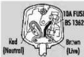
The appliance cord is terminated with a UK approved mains plug fitted with a 13A fuse. If the fuse needs to be replaced, on ASTA or BSI approved BST 362 fuse rated at 10A must be used. If you need to change the mains plug, remove the fuse and dispose of this plug safely immediately after cutting it from the cord.
Connecting a Mains Plug
The wires in the mains lead are coloured in accordance with the code: Red: NEUTRAL; Brown: LIVE:
As these colours may not correspond to the coloured markings identifying the terminals in your plug, proceed as follows:
The red wire must be connected to the terminal marked with the letter N or coloured red or BLACK. The BROWN wire must be connected to the terminal marked with the letter L or coloured BROWN or RED.

To indicate that the marked item can be hot and should touched without taking care.
Page 8
Page 1
2: Introduction
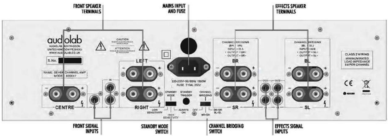
text_image
FRONT SPEAKER TERMINALS CAUTION MAINS INPUT AND FUSE AUDOLAB AUDIO UNITED KINOW PE296XU WWW.AUDOLAB.CO.UK S.No. NAME: SEVEN MODE CHANNELAMP R200X7 CENTRE LEFT RIGHT STANDBY MODE SWITCH STANDBY MODE STANDBY TNGGER CHANNEL BRIODING BR+SR BR+SL CHANNEL BRIDGING (BR-, SR) INPUT < IN A + OUTPUT > BR+ - OUTPUT > BR+ CHANNEL BRIDGING (BL-, SL) INPUT < IN B + OUTPUT > SL+ - OUTPUT > SL+ EFFECTS SPEAKER TERMINALS BR- SR- SL- INT OUT IN OUT IN OUT IN OUT IN OUT IN OUT IN OUT IN OUT IN OUT IN OUT IN OUT IN OUT IN OUT IN OUT IN OUT IN OUT IN OUT IN OUT IN OUT IN OUT IN OUT IN OUT IN OUT IN OUT IN OUT IN OUT OUT IN OUT IN OUT IN OUT IN OUT IN OUT IN OUT IN OUT IN OUT IN OUT IN OUT IN OUT IN OUT IN OUT IN OUT IN OUT IN OUT IN OUT IN OUT IN OUT IN OUTIntroduction
The Audieleb 8200X7 is a seven channel power amplifier of impeccable specification. In 7-channel configuration it produces 100W of continuous power into 8 Ohms on all channels. The amplifier can be readily configured to provide five channels of 100W and one channel of 150W (6 ch. set-up), or three channels of 100W and two channels of 150W (5 ch. set-up).
The amplifier can be set up so that it switches itself to a standby mode when not in use to minimise power consumption. It returns from standby to active on receiving a signal input or external trigger; alternatively it can be set to stay permanently active.
The 8200X7 includes comprehensive but completely unobtrusive protection against overload, excessively prolonged clipping, DC offsets, and high temperatures.
The 8200X7 has a sophisticated muting system, which stops you hearing loud, annoying switching noises and protects the amplifier and the loudspeakers. Particular care has been taken to make sure that the muting
circuitry, when switched off, does not affect the sound quality. For this purpose carefully selected relays with minimal crosstalk between coil and contacts have been used.
Unpacking
Unpack the product fully. The carton should contain:
The Audiolab 8200X7
One IEC power cord suitable for your area
- This instruction manual
Report any damage or shortage to your dealer as soon as possible. Retain the packing if possible. If you dispose of the packing, do so with regard to any recycling regulations in your area.
Please retain this User Manual. In the unlikely event that you pass your 8200X7 on to a third party, please Include this manual.
Page 2
Positioning
The 820017 dissipates large amounts of heat when operating.
Place the 820007 on an open, level and sturdy flat surface.
- Avoid operating the amplifier on a soft surface, such as thick carpet, which could block ventilation slots under the unit.
Please ensure that there is adequate ventilation above and below the unit. It is important that the cooling slots in the top and bottom are not obstructed, and there is sufficient space around the unit to allow for the free circulation of air.
Do not use in a cabinet or other confined space.
Do not place any equipment on top of the amplifier.
Controls
The 8200X7 is designed for the simplest possible operation, and the only controls are two switches on the rear panel. One sets the standby mode and the other the channel bridging. There are no front panel controls.
6: Operation
Switching On
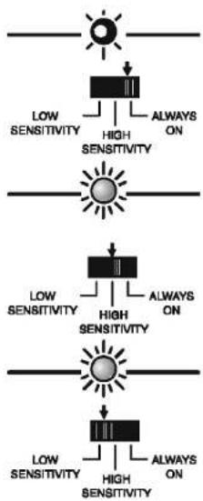
Connect the mains cable to the amplifier, and then switch on at the wall socket. The red power LED will glow dimly to indicate that power is applied but the amplifier is in standby mode. In this condition the loudspeakers are disconnected by the internal muring relays and the amplifier circuitry is powered off.
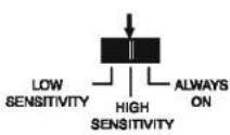
If the standby mode switch on the rear is set to 'ALWAYS ON' (right position), after a short delay the amplifier will go to the active state and the red power LED will glow brightly.
In the two other positions the amplifier will remain in standby until it receives an audio signal of sufficient amplitude, or a trigger voltage from the AV processor is applied to the rear jack socket.
This switch may be freely operated when the unit is powered.
Audio Signal Activation
If the Standby Mode switch on the rear is set to "HIGH SENSITIVITY" (middle position) and there is no external trigger voltage, the amplifier will remain in standby until an audio signal is applied. It will then become active and the red power LED will glow brightly. The amplifier will remain active for 15 minutes after all audio signals have ceased and will then return to standby. This delay prevents the amplifier from going to standby during brief programme interruptions e.g while changing discs.
If the standby mode switch is set to 'LOW SENSITIVITY', operation is as for high sensitivity except that the incoming audio signal must be at a higher level before the unit switches on. Use this setting in electrically noisy environments if there are problems with spurious activation, especially if the amplifier is operated in a 5 or 6 channel configuration and the outputs are not bridged. Refer to Section S.
Trigger Activation
When the AV processor is activated the processor's trigger circuit sends a pulse to the 8200X7. After a short delay the amplifier will go to the active state and the red power LED will glow brightly. (See section 3)
If the amplifier is set to 'Always On', the trigger switch has no effect.
flowchart
graph TD
    A["Sun"] --> B["Low Sensitivity"]
    B --> C["High Sensitivity"]
    C --> D["Always ON"]
    E["Sun"] --> F["Low Sensitivity"]
    F --> G["High Sensitivity"]
    G --> H["Always ON"]
    I["Sun"] --> J["Low Sensitivity"]
    J --> K["High Sensitivity"]
    K --> L["Always ON"]
STANDBY TRIGGER

Protection Modes
If the amplifier needs to protect itself against abnormal conditions, it will go into standby mode, and disconnect the loudspeakers. It will then attempt to re-enter the active state after a short delay. If the abnormal conditions persist, after the third attempt the amplifier will stay in standby mode indefinitely until manually reset by removing and reinserting the mains cable.
Short-term overload protection: Sustained short-circuit, overload heavy clipping in any channel will send the unit into standby mode. After a few seconds the unit will attempt to activate itself. After three attempts the amplifier will stay indefinitely in standby mode. Remove the mains plug, wait for a short time before re-inserting the plug.
Overload protection signal: Power LED will dim with one bright flash every second.
Over-temperature protection: Overheating within the amplifier as a result of blocked ventilation slots or other abnormal conditions will send the unit into standby mode. After three attempts to re-activate the amplifier will stay indefinitely in standby mode. Remove the mains plug, wait for the amplifier to cool down completely and before re-inserting the plug.
Over-temperature signal: Power LED will dim with two bright flashes every second.
DC offset protection: Caused by internal amplifier fault or a large DC input signal. The unit will go into standby mode. After a few seconds the unit will attempt to activate. After three attempts the amplifier will stay indefinitely in standby mode. Remove the mains plug, wait a short time and re-insert the plug.
DC offset protection signal: Power LED will dim with three flashes every second. It is highly unlikely that you will ever see this indication; if you do please unplug the amplifier at once and arrange for it to be checked by an authorised service personnel.
Phase
It is essential that the loudspeaker connections are secure and with the positive and negative terminals correctly connected.
This becomes especially important in multi-channel systems where the effects of one or more incorrectly connected (out of phase) loudspeakers may severely impair the sound and yet be difficult to detect.
If the sound appears muddled and lacking clarity this may be because one or more speaker connections are not correctly mode. Always check loudspeaker connections carefully when you have made any alteration to your system.
5c: 5-Channel Connections
Switch power off before making connections!
text_image
Set the Channel Bridging Switch to BR+SR/BL+SL CHANNEL BRIDGING OFF BR+SR BL+SL CENTRE SPEAKER SIGNAL CENTRE REAR LEFT SIGNAL CAUTION RISK OF ELEKTIEN CHICKER SENSITIVE ATTENTION RISK OF ELEKTIEN CHICKER SENSITIVE LEFT SPEAKER RIGHT STANDBY MODE STANDBY TRIGGER HIGH SENSITIVITY LOW SENSITIVITY STANDBY MODE STANDBY TRIGGER OFF SR+SR BR+SR BL+SL Z20-250V~56/80Hz 1530V FUSE T10AL 260V FRONT RIGHT BR SPEAKER CHANNEL BRIDGING (BL + SL) INPUT = IN B OUTPUT = IN B OUTPUT = SL BR SPEAKER FRONT LEFT BR+SR IN IN SL8200X7 5-Channel Connections
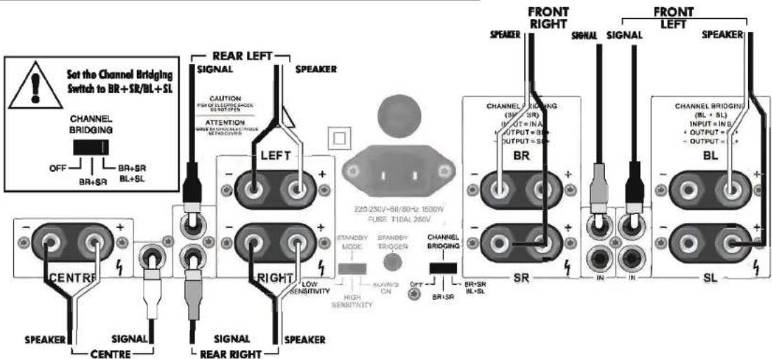
⊗ Ensure the power to the amplifier is OFF
Switch the Channel Bridging Switch to the right position marked BR+SR/BL+SL
⊗ Connect the signal inputs to the appropriate channels of the AV amplifier.
⊗ Connect the loudspeaker terminals to the correct speakers.

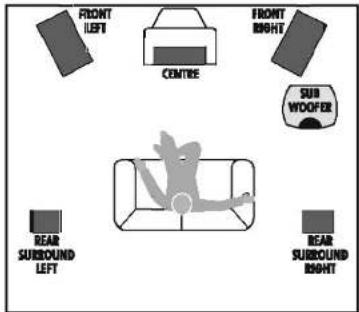
For optimum performance, In 5-Channel configuration the Front Left and Front Right speakers are connected to the bridged amplifier channels and the other speakers are connected as shown in the diagram.
Please note that these connections differ from the connections marked on the amplifier.
Connect the + (RED) terminal of each amplifier channel to the corresponding + (RED) terminal of the loudspeaker. Connect the - (BLACK) terminal of each amplifier channel to the corresponding - (BLACK) terminal of the loudspeaker. Ensure there are no loose strands of wire that can short the terminals out.
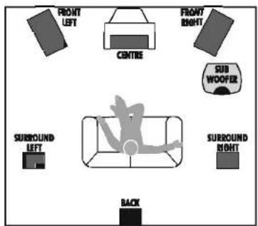
text_image
FRONT LEFT CENTRE FRONT RIGHT SUB WOOFER BEAR SURBOUND LEFT BEAR SURBOUND RIGHT
3: Connections & Cables
Switch power off before making connections!
Connecting Loudspeakers
Switch power off before connecting loudspeakers.
Use good quality low resistance loudspeaker cable. The left and right channel pairs should be connected with equal lengths of cable.
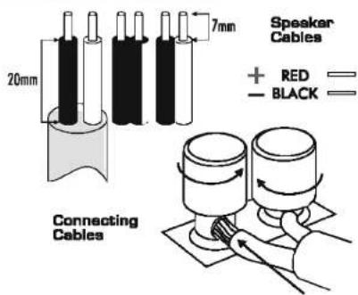
Connect the Positive RED (+) terminal of the amplifier to the Positive (+) RED terminal of the loudspeaker. Connect the Negative (-) BLACK terminals similarly.
Tighten the loudspeaker terminals securely by hand. Make there are no loose strands of wire which could cause shorts.
text_image
Speaker Cables + RED — — BLACK — 20mm 7mm Connecting CablesConnecting the Trigger
A trigger gives you the option of switching the amplifier on and off every time the AV processor is switched on and off.
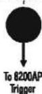
If your AV processor has a trigger output, this should be connected to the trigger input of the 820007 via the 3.5mm jack socket. Your dealer will be able to supply you with a suitable interconnect.
When used with the B200AP the trigger input should be connected. The control function is carried out by the B200AP, and the B200X7 is the slave unit. The Sensitivity switch should be set to high when used with the B200X7.
See Section 6 for further information on the operation of the trigger.
Connecting to an AV Processor
You will require a preamplifier, or ideally a multichannel AV processor, such as the Audiolab B200AP to provide the signals to drive the 8200X7.
Each output should be connected to the matching input on the 8200X7.
To connect the source equipment to the 8200X7, you should use a high quality, well screened RCA-RCA audio cable.
Push the connectors fully home to secure a firm connection.
All the RCA-RCA cables should be arranged so they are bundled as closely together as possible, especially at the rear of the amplifier. This minimises the chances of cable loops picking up magnetic fields and degrading performance.
The 8200X7 can be configured for 5 channel, 6 channel or 7 channel applications depending on your AV processor. If you are in any doubt, consult your dealer.
B200X7 INPUT CONNECTIONS
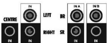
text_image
CENTRE IN IN LEFT BR RIGHT SR IN A IN IN IN BTrigger and Sensitivity Settings for use with the Audiolab 8200AP
STANDBY TRIGGER
4: Bridging
Standard and Bridged Connections
Bridging is a technique that enables two amplifiers to drive a single loudspeaker. When you balance the channel levels via the AV processor, the bridged channel/s will play at exactly the same level as all the other channels.
Note: These matching levels will be maintained regardless of the setting of the master volume control. However, more power is available at the bridged output to provide a cleaner, punchier sound to the loudspeaker.
To use bridged modes of operation you must alter the position of the channel bridging slide switch on the rear of the unit. This has three positions-equivalent to 7-Channel, 6-Channel and 5-Channel operation.
7-Channel Mode: [OFF]
7 channels each of 100W are available. If your system has 6 or 5 channels, the unused channel/s can be safely left unconnected. Alternatively, the amplifier can be switched to provide extra power to one or more channels as described below.
6-Channel Mode: (BR+SR)
This provides 5 channels of 100W and one bridged channel of 150W. The bridged channel should be used to drive the centre speaker as shown in Section Sb.
5-Channel Mode: (BR+SR: BL+SL)
This provides 3 channels of 100W and two bridged channels of 150W. The bridged channels should be used to drive the front left and right speakers. Refer to diagram 5c.
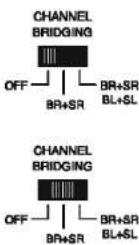
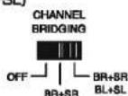

NEVER OPERATE THE BRIDGING SWITCH WHEN THE AMPLIFIER IS SWITCHED ON. THE SUDDEN SURGE MAY DAMAGE YOUR SPEAKERS IRREPARABLY.

5a: 7-Channel Connections
Switch power off before making connections!
text_image
Set the Channel Bridging Switch to OFF CHANNEL BRIDGING OFF BR+SR BR+SR BL+SL REAR LEFT SIGNAL CAUTION RUN OF ELECTRIC SWITCH OUT TO OUT ATTENTION BEAT TO CHINA STRAVING BEAT TO CHINA LEFT 220-230V-50/50Hz 1500W FUSE T10AL 250V CORDED RIGHT LEAVES STANDBY MODE STANDBY TRIGGER CHANNEL BRODING BR+SR BR+SR SL SPECTRUM HIGH SENSITIVITY ALLWAYS ON OFF BR+SR BR+SR BR+SR BR+SR BR+SR BR+SR BR+SR BR+SR BR+SR BR+SR BR+SR BR+SR BR+SR BR+SR BR+SR BR+SR BR+SR BR+SR BR+SR BR+SR BR+SR BR+SR BR+SR BR+SR BR+SR BR+ SR BR+SR BR+SR BR+SR BR+SR BR+SR BR+SR BR+SR BR+SR BR+SR BR+ SR BR+ SR BR+ SR BR+ SR BR+ SR BR+ SR BR+ SR BR+ SR BR+ SR BR+ SR BR+ SR BR+ SR BR+ SR BR+ SR BR+ SR BR+ SR BR+ SR BR+ SR BR+ SR BR+ SR BR+ SR BR+ SR BR+ SR BR+ SR BR+ SR BR+ SRL BR+ SRL BR+ SRL BR+ SRL BR+ SRL BR+ SRL BR+ SRL BR+ SRL BR+ SRL BR+ SRL BR+ SRL BR+ SRL BR+ SRL BR+ SRL BR+ SRL BR+ SRL BR+ SRL BR+ SRL BR+ SRL BR+ SRL BR+ S RLB200X7 7-Channel Connections
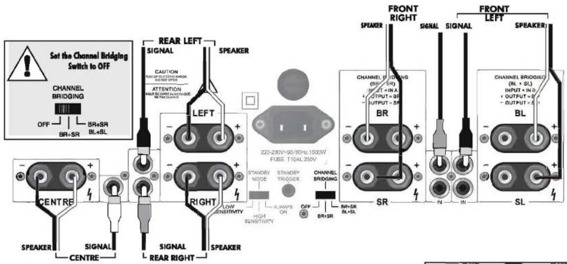
⑧ Ensure the power to the amplifier is OFF
⊗ Switch the Channel Bridging Switch to OFF
⑧ Conned the signal inputs to the appropriate channels of the AV amplifier.
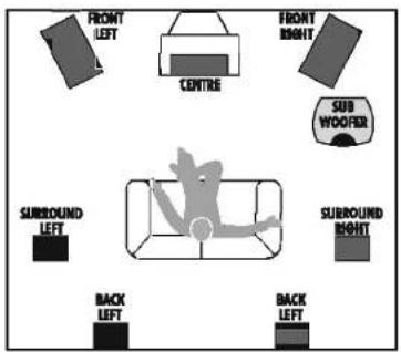
⊗ Connect the loudspeaker terminals to the correct speakers. Refer to the drawing at the bottom right of this page for guidance.
Connect the + (RED) terminal of each amplifier channel to the corresponding + (RED) terminal of the loudspeaker. Connect the - (BLACK) terminal of each amplifier channel to the corresponding - (BLACK) terminal of the loudspeaker. Ensure there are no loose strands of wire that can short the terminals out.
text_image
FRONT LEFT CENTRE FRONT RIGHT SUB WOOFER SURROUND LEFT SUBROUND RIGHT BACK LEFT BACK LEFT
5b: 6-Channel Connections
Switch power off before making connections!
text_image
Set the Channel Bridging Switch to BR+SR CHANNEL BRIDGING OFF BR+SR BR+SR BL+SL - CENTRE + SPEAKER - SIGNAL - CENTRE - REAR LEFT SIGNAL CAUTION RIGHT ELECTRIC BLOCK SENSOR INPUT ATTENTION RANGE OUT OF OVER ELECTRICAL BEANS IN CHINA LEFT - - - - - - - - - - - - - - - - - - - - - - - - - - - - - - - - - - - - - - - - - - - - - - - - - - - - - - - - - - - - - - - - - - - - - - - - - - - - - - - - - - - - - - - - - - - - - - - - - - - - - - - - - - - - - - - - - - - - - - - - - - - - - - - - - - - - - - - - - - - - - - - - - - - - - - - REAR RIGHT SPEAKER RIGHT LOW SENSITIVITY STANDBY MODE STANDBY STRICER ALLWAYS ON HIGH SENSITIVITY OFF BR+SR BR+SR BL+SL FRONT SPEAKER RIGHT BR SIGNAL OUTPUT = 0.0V OUTPUT = 5V BR SIGNAL BRIODING (BR+SR) IN IN IN IN IN IN IN IN IN IN IN IN IN IN IN IN IN IN IN IN IN IN IN IN IN IN IN IN IN IN IN IN IN IN IN IN IN IN IN IN IN IN IN IN IN IN IN IN IN IN IN8200X7 6-Channel Connections
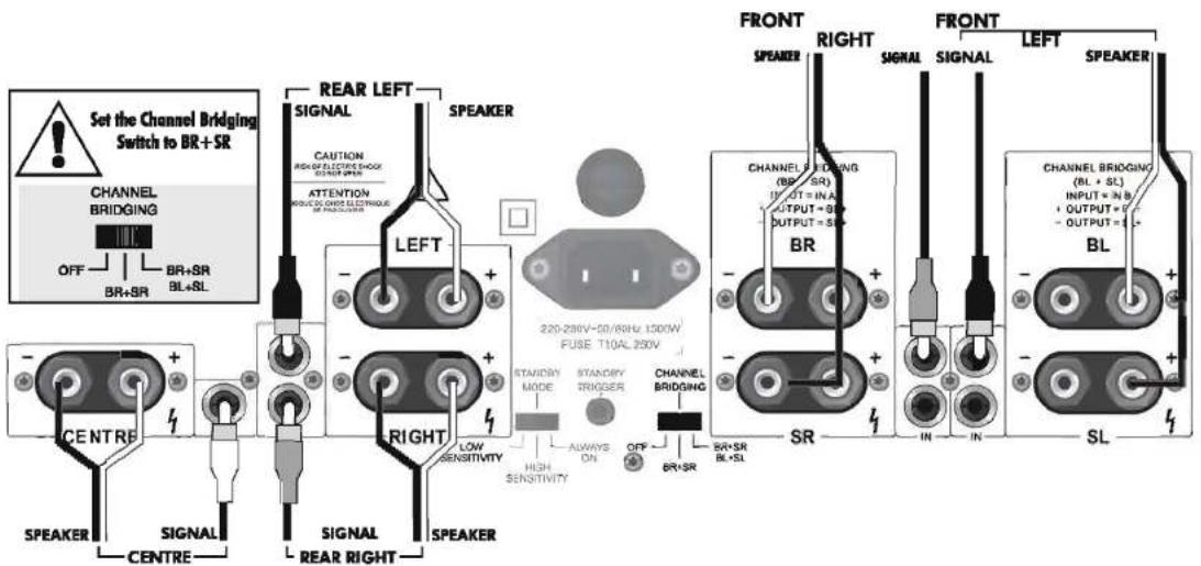
⊗ Ensure the power to the amplifier is OFF
Switch the Channel Bridging Switch to the middle position marked "BR + SR"
Connect the signal inputs to the appropriate channels of the AV amplifier.
⊗ Connect the loudspeaker terminals to the correct speakers.

Although the bridged channel can be used for the Back channel, a better use is to connect the Centre channel speaker (and the Centre channel output from the AV processor) to this channel and connect the Back speaker (and the Back channel output from the AV processor) to the Centre channel output. The suggested connections are shown on the diagram. Please note that these connections differ from the connections marked on the amplifier.
☒ Please follow the diagram carefully so as to connect your speakers correctly.