
YST-C30 - Hi-Fi-System YAMAHA - Kostenlose Bedienungsanleitung
Finden Sie kostenlos die Bedienungsanleitung des Geräts YST-C30 YAMAHA als PDF.

| Produkttyp | Hi-Fi-Komponentensystem |
| Modell | YST-C30 (auch YST-C10) |
| Marke | Yamaha |
| Abmessungen (Hauptgerät) | 300 × 268 × 294 mm (11-13/16" × 10-9/16" × 11-9/16") |
| Gewicht (Hauptgerät) | 7,5 kg (16 lb 8 oz) |
| Abmessungen Lautsprecher (einzeln) | 324 × 232 × 232 mm (12-3/4" × 9-1/8" × 9-1/8") |
| Gewicht Lautsprecher (einzeln) | 4,3 kg (9 lb 7 oz) |
| Stromversorgung | AC 120 V, 60 Hz (US/Canada); AC 220–240 V, 50/60 Hz (andere Regionen) |
| Leistungsaufnahme | 95 W (US), 145 W (Kanada), 250 W (Europa/Australien) |
| Verstärkerleistung | 2 × 24 W (1 kHz, 6 Ω, 0,5 % THD) |
| Frequenzbereich | 35 Hz – 20 kHz (YST-C30) |
| Klangeinstellung | Graphischer Equalizer (100 Hz/500 Hz/2 kHz/10 kHz, ±8 dB), Balance-Regler (YST-C30) |
| Radio-Empfang | UKW (87,5–108 MHz), MW (530–1720 kHz), LW (153–281 kHz, nur UK/EU) |
| Sender-Speicher | 30 Sender (20 UKW + 10 MW) mit Preset-Funktion |
| CD-Player | 16-Bit-Digitalfilter, Programmwiedergabe, Intro-Wiedergabe, Repeat, Direktanwahl |
| Kassettendeck | Auto-Reverse-Doppelkassettendeck, Dolby-B-Rauschunterdrückung |
| Tonbandfunktionen | Kopieren von Kassette A nach B, Aufnahme von CD/Tuner/AUX |
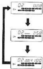
| Timer | Einschlaf-Timer (bis 3 h 45 min) und Weck-Timer (einmalig, 60 min) |
| Fernbedienung | Infrarot-Fernbedienung mit Nummerntasten für CD/Tuner, Lautstärke, Eingangswahl |
| Anschlüsse | AUX-Eingang (Cinch), Kopfhörer (3,5 mm), Antennenanschlüsse |
| Sicherheit | Netzstecker ziehen bei Gewitter, nicht öffnen, vor Nässe schützen |
| Wartung & Reinigung | CD-Oberfläche von innen nach außen reinigen; Kopfreinigung bei Kassettenstaub |
| Reparatur | Nur durch autorisiertes Fachpersonal, keine vom Benutzer zu wartenden Teile |
| Zubehör | Fernbedienung, AAA-Batterien (2x), AM-Rahmenantenne, FM-Stabantenne, Lautsprecherkabel (2x) |
Häufig gestellte Fragen - YST-C30 YAMAHA
Benutzerfragen zu YST-C30 YAMAHA
0 Frage zu diesem Gerät. Beantworten Sie die, die Sie kennen, oder stellen Sie Ihre eigene.
Eine neue Frage zu diesem Gerät stellen
Laden Sie die Anleitung für Ihr Hi-Fi-System kostenlos im PDF-Format! Finden Sie Ihr Handbuch YST-C30 - YAMAHA und nehmen Sie Ihr elektronisches Gerät wieder in die Hand. Auf dieser Seite sind alle Dokumente veröffentlicht, die für die Verwendung Ihres Geräts notwendig sind. YST-C30 von der Marke YAMAHA.
BEDIENUNGSANLEITUNG YST-C30 YAMAHA
YAMAHAYST-C30/C10
NATURAL SOUND COMPACT COMPONENT SYSTEM
Newly developed Active Servo Technology system
Amplifier with high power output
Digital tuner with 30-station preset memory
CD player with versatile play functions
Auto reverse double cassette deck
Convenient remote control standard
High tech look
CENTER
CONTENTS
Safety Instructions....
Caution....
Major Difference between
the YST-C30 and YST-C10
Accessories.
Attaching and Removing Speakers
(☆ YST-C10 only) 5
Connections.
Names and Functions of Parts ..... 10
Remote Control. 15
Volume and Tone Adjustments ..... 17
Listening to Radio Broadcast....17
| Notes About HandlingCompact Discs | 18 |
| Playing Compact Discs | 19 |
| Notes About Handling | |
| Cassette Tapes | 22 |
| Cassette Tape Play | 22 |
| Recording | 24 |
| Tape Editing (dubbing) | 25 |
| Using the Timer | 26 |
| Troubleshooting | 28 |
| Specifications | 30 |
OWNER'S MANUAL
IMPORTANT!
Please record the serial number of your unit in the space below.
Model: YST-C30/YST-C10
Serial No.:
The serial number is located on the rear of the unit.
Retain this Owner's Manual in a safe place for future reference.

Explanation of Graphical Symbols

The lightning flash with arrowhead symbol, within an equilateral triangle, is intended to alert you to the presence of uninsulated "dangerous voltage" within the product's enclosure that may be of sufficient magnitude to constitute a risk of electric shock to persons.

The exclamation point within an equilateral triangle is intended to alert you to the presence of important operating and maintenance (servicing) instructions in the literature accompanying the appliance.
WARNING
TO REDUCE THE RISK OF FIRE OR ELECTRIC SHOCK, DO NOT EXPOSE THIS APPLIANCE TO RAIN OR MOISTURE
SAFETY INSTRUCTIONS
1 Read Instructions—All the safety and operating instructions should be read before the appliance is operated.
2 Retain Instructions—The safety and operating instructions should be retained for future reference.
3 Heed Warnings—All warnings on the appliance and in the operating instructions should be adhered to.
4 Follow Instructions—All operating and other instructions should be followed.
5 Water and Moisture—The appliance should not be used near water—for example, near a bathtub, washbowl, kitchen sink, laundry tub, in a wet basement, or near a swimming pool, etc.
6 Carts and Stands—The appliance should be used only with a cart or stand that is recommended by the manufacturer.
6A An appliance and cart combination should be moved with care. Quick stops, excessive force, and uneven surfaces may cause the appliance and cart combination to overturn.

7 Wall or Ceiling—The appliance should be mounted to a wall or ceiling only as recommended by the manufacturer.
8 Ventilation—The appliance should be situated so that its location or position does not interfere with its proper ventilation. For example, the appliance should not be situated on a bed, sofa, rag, or similar surface, that may block the ventilation opening; or cabinet that may impede the flow of air through the ventilation openings.
9 Heat—The appliance should be situated away from heat sources such as radiators, stoves, or appliances that produce heat.
10 Power Sources—The appliance should be connected to a power supply only of the type described in the operating instructions or as marked on the appliance.
11 Power-Cord Protection—Power-supply cords should be routed so that they are not likely to be walked on or pinched by items placed upon or against them, paying particular attention to cords at plugs, convenience receptacles, and the point where they exit from the appliance.
12 Cleaning—The appliance should e cleaned only as recommended by the manufacturer.
13 Lightning and Non-use Periods—For protection from power surges during a lighting strom, or when the appliance is left unused for long periods of time, the unit should be unplugged form the wall outlet and disconnected from the antenna or cable system.
14 Object and Liquid Entry—Care should be taken so that objects do not fall into and liquids are not spilled into the inside of the appliance.
15 Damage Requiring Service—The appliance should be serviced by qualified service personnel when:
A. The power-supply cord or the plug has been damaged; or
B. Objects have fallen, or liquid has been spilled into the appliance; or
C. The appliance has been exposed to rain; or
D. The appliance does not appear to operate normally or exhibits a marked change in performance; or
E. The appliance has been dropped, or the cabinet damaged.
16 Servicing—The user should not attempt to service the appliance beyond those means described in the operating instructions. All other servicing should be referred to qualified service personnel.
17 Power Lines—An outdoor antenna should be located away from power lines.
18 Grounding or Polarization—The precautions that should be taken so that the grounding or polarization of an appliance is not defeated.
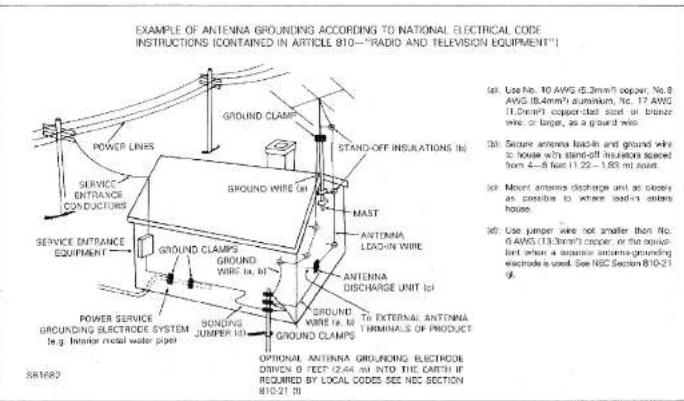
19 Outdoor Antenna Grounding—If an outside antenna or cable system is connected to the appliance, be sure the antenna or cable system is grounded so as to provide some protection against voltage surges and built-up static charges. Section 810 of the National Code, ANSI/NFPA
No. 70-1984, provides information with respect to proper grounding of the mast and supporting structure, grounding of the lead-in wire to an antenna discharge unit, size of grounding electrodes, and requirements for the grounding electrode.
20 Speaker Connection—To reduce the risk of shock or fire and prevent short circuits, strictly follow the instructions for connecting speakers described in this manual.
CAUTION: READ THIS BEFORE OPERATING YOUR UNIT.
1 To ensure the finest performance of this unit, please read this manual carefully. Keep it in a safe place for future reference.
2 This unit is equipped with the newly developed Active Servo Processing Speaker System. It is not designed for use with conventional speakers. Therefore, do not attempt to connect other speakers than the provided speakers, that is, YST-SC30 or YST-SC10.
3 Choose the installation location of this unit carefully. Avoid placing it in direct sunlight or close to a source of heat. Also avoid locations subject to vibration and excessive dust, heat, cold or moisture. Keep it away from sources of hum such as transformers and electric motors.
4 Do not operate this unit upside-down. It may overheat, possibly causing damage.
5 Never open the cabinet. If a foreign object drops into the set, contact your dealer.
6 Do not place CD or other objects on top of this unit.
7 Do not use force on switches, knobs or cords. When moving the set, first turn the unit off. Then gently disconnect the power plug. Never pull the cord itself.
8 Do not attempt to clean the unit with chemical solvents; this might damage the finish. use a clean, dry cloth.
9 Be sure to read the "TROUBLESHOOTING" section (See page 28.) on common operating errors before concluding that this unit is faulty.
10 To prevent lightning damage, pull out the power cord and remove the antenna cable during an electrical storm.
11 The CD player in this unit generates and uses radio frequency energy and if not installed and used properly, that is, in strict accordance with the manufacturer's instructions, may cause interference to radio and television reception. It has been type tested and found to comply with the limits for a Class B computing device in accordance with the specifications in Subpart J of Part 15 of FCC Rules, which are designed to provide reasonable protection against such interference in a residential installation.
However, there is no guarantee that interference will not occur in a particular installation. If this unit does cause interference to radio or television reception, which can be determined by turning the equipment off and on, the user is encouraged to try to correct the interference by one or more of the following measures:
Reorient the receiving antenna.
Relocate this unit with respect to the radio or TV receiver.
Move this unit away from the radio or TV receiver.
Connect this unit to a different AC outlet so that this unit and the radio or TV receiver are on different electrical circuits.
If necessary, the user, should consult the dealer or an experienced radio/television technician for additional suggestions. The user may find the followig booklet prepared by the Federal Communications Commission helpful: "How to Identify and Resolve Radio-TV Interference problems."
This booklet is available from the U.S. Government Printing Office, Washington, DC 20402, Stock No. 004-000-00345-4.
12 Never allow metallic items (e.g. screwdrivers, tools, etc.) to come near the cassette deck's record/play-back head assembly in this unit. Doing so may not only scratch or damage the head's mirror-smooth finish, it may change the magnetic characteristics of the heads, causing a deterioration in reproduction performance quality.
13 Although the cassette deck's record playback heads used in this unit are high quality heads with outstanding reproduction characteristics, they can become dirty through the use of old tapes or from dust accumulation over time. This can have a serious effect on reproduction quality. Clean the heads regularly with one of commonly available head cleaners or with cleaning solutions.
14 Voltage Selector (Regular models only): The voltage selector on the rear panel of this unit must be set for your local mains voltage BEFORE plugged in the AC mains supply.
WARNING
To reduce the risk of fire or electric shock, do not expose this appliance to rain or moisture.
To avoid electrical shock, do not open the cabinet. Refer servicing to qualified personnel only.
DANGER
Invisible laser radiation when open and
interlock failed or defeated.
Avoid direct exposure to beam.
CAUTION
Use of controls or adjustments or performance of procedures other than those specified herein may result in hazardous radiation exposure.

This compact disc player is classified as a CLASS 1 LASER product.
The CLASS 1 LASER
PRODUCT label is
located on the rear exterior.
Laser component in this product is capable of emitting radiation exceeding the limit for Class 1.
MAJOR DIFFERENCE BETWEEN THE YST-C30 AND YST-C10
This instruction manual covers the operation of both the YST-C30 and YST-C10 systems. Items marked with a ★ refer to YST-C30 functions. Items marked with a ☆ refer to YST-C10 functions. All illustrations show the YST-C30.
☆ YST-C10
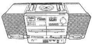
natural_image
Line drawing of a portable electronic device with front panel and control buttons (no readable text or symbols)★ YST-C30
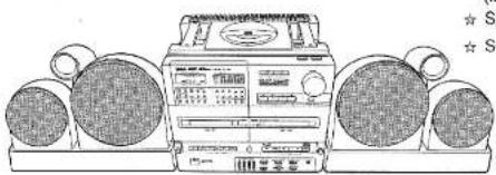
natural_image
Illustration of a vintage portable radio with two large earbuds and a front-mounted control unit (no visible text or symbols)ACCESSORIES
Check to make sure that the following items are included with your system:
(included with the ★ YST-C30/☆ YST-C10)
★ ☆ Remote control (VH34720).... 1 pc.
★ ☆ AAA batteries (UM-4) 2 pcs.
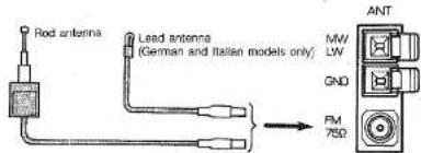
★ ☆ AM Loop antenna 1 pc.
★ ☆ FM Wire antenna (Regular, German and Italian models only).... 1 pc.
★☆ Rod Antenna (U.S.A., Canadian, Australian, U.K. and European-except German and Italian models only).... 1 p
★ ☆ Antenna holder (-ditto-).... 1 pc.
★ ☆ Screws (-ditto-).... 3 pcs.
★ ☆ Connection wire (-ditto-).... 1 pc.
★ ☆ Converter plug (U.K. and European models only).... 1 pc.
★ ☆ Speaker cables (with connectors)...... 2 pcs.
(Included with the ☆ YST-C10 only)
☆ Speaker attachment fittings .... 2 pcs.
☆ Screws 4 pcs.
SPEAKER PLACEMENT FOR YST-C30:
By altering the speaker placement, you can tailor the soundstage to match your individual listening preferences.
Two types of speaker placement are possible to let you enjoy the unique characteristics of this speaker system (YAMAHA YST-SC30) to the full.
(1) For the most expansive sound possible, place the speakers so that the tweeters are positioned near the outer edges (as in the above illustration.)
(2) For precisely focused sonic imaging, place the speakers so that the woofers are positioned near the outer edges.
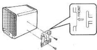
ATTACHING AND REMOVING SPEAKERS (☆ YST-C10 only)
■ Speaker attachment
-
Attach the speaker attachment fittings to the speakers using the screws provided as shown in the diagram.
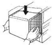
-
Slide the speakers downward until they snap into place.
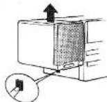
■ Speaker removal
Hold down the button on the side of the unit and raise the speaker to disengage it.
Note: Take care not to bump or drop speakers.
THE ACTIVE SERVO TECHNOLOGY SYSTEM
The Active Servo Technology system controls the operation of the speaker units directly. It employs an active servo processing amplifier for dramatically improved driving and damping force compared with conventional systems and active servo processing speakers with specially tuned enclosures. The result is powerful, bass and linear response characteristics which you would expect to find any issues
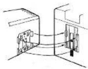
- Align the speaker attachment fittings with the notches in the sides of the unit as shown. First align the top portion of the speaker attachment fitting with the notch in the side of the unit, then the lower portion.
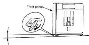
■ Fold-out legs
Fold out the legs under the front panel if you wish to tilt the unit slightly upwards.
CONNECTIONS
■ ANTENNA CONNECTIONS
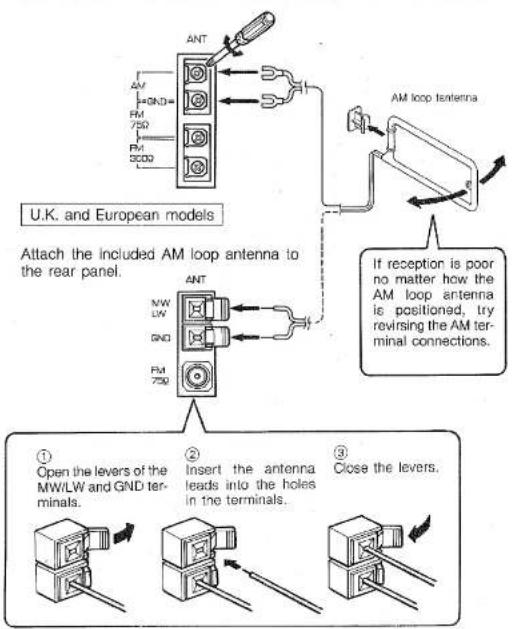
- Connecting the AM loop antenna:
U.S.A., Canadian, Australian and Regular models
Attach the included AM loop antenna to the rear panel. Use a Phillipshead screwdriver to connect the antenna leads to the AM terminals.
flowchart
graph TD
    A["AM loop antenna"] --> B["AM loop antenna to rear panel"]
    B --> C["Analog/Amplifier/Analog/Amplifier/Amplifier/Amplifier/Amplifier/Amplifier/Amplifier/Amplifier/Amplifier/Amplifier/Amplifier/Amplifier/Amplifier/Amplifier/Amplifier/Amplifier/Amplifier/Amplifier/Amplifier/Amplifier/Amplifier/Amplifier/Amplifier/Amplifier/Amplifier/Amplifier/Amplified"]
    C --> D["Analog/Amplifier/Amplifier/Amplifier/Amplifier/Amplifier/Amplifier/Amplifier/Amplifier/Amplifier/Amplifier/Amplifier/Amplifier/Amplifier/Amplifier/Amplifier/Amplifier/Amplifier/Amplifier/Amplifier/Amplifier/Amplified"]
    D --> E["Analog/Amplifier/Amplifier/Amplifier/Amplifier/Amplifier/Amplifier/Amplifier/Amplifier/Amplifier/Amplifier/Amplifier/Amplifier/Amplifier/Amplifier/Amplifier/Amplified"]
    E --> F["Analog/Amplifier/Amplifier/Amplifier/Amplifier/Amplifier/Amplifier/Amplifier/Amplifier/Amplifier/Amplifier/Amplifier/Amplifier/Amplifier/Amplified"]
    F --> G["Analog/Amplifier/Amplifier/Amplifier/Amplifier/Amplifier/Amplifier/Amplifier/Amplifier/Amplifier/Amplifier/Amplifier/Amplifier/Amplified"]
    G --> H["Analog/Amplifier/Amplifier/Amplifier/Amplifier/Amplifier/Amplifier/Amplifier/Amplifier/Amplifier/Amplifier/Amplifier/Amplifier/Amplified"]
    H --> I["Analog/Amplifier/Amplifier/Amplifier/Amplifier/Amplifier/Amplifier/Amplifier/Amplifier/Amplifier/Amplifier/Amplifier/Amplified"]
    I --> J["Analog/Amplifier/Amplifier/Amplifier/Amplifier/Amplifier/Amplifier/Amplifier/Amplifier/Amplifier/Amplifier/Amplified"]
    J --> K["Analog/Amplifier/Amplifier/Amplifier/Amplifier/Amplifier/Amplifier/Amplifier/Amplifier/Amplifier/Amplified"]
    K --> L["Analog/Analog current transformer, which is connected to the terminal of the U.K. and European models"]
    L --> M["Analog current transformer, which is connected to the terminal of the U.K. and European models"]
    M --> N["Analog current transformer, which is connected to the terminal of the U.K. and European models"]
    N --> O["Analog current transformer, which is connected to the terminal of the U.K. and European models"]
    O --> P["Analog current transformer, which is connected to the terminal of the U.K. and European models"]
    P --> Q["Analog current transformer, which is connected to the terminal of the U.K. and European models"]
    Q --> R["Analog current transformer, which is connected to the terminal of the U.K. and European models"]
    R --> S["Analog current transformer, which is connected to the terminal of the U.K. and European models"]
    S --> T["Analog current transformer, which is connected to the terminal of the U.K. and European models"]
    T --> U["Analog current transformer, which is connected to the terminal of the U.K. and European models"]
    U --> V["Analog current transformer, which is connected to the terminal of the U.K. and European models"]
    V --> W["Analog current transformer, which is connected to the terminal of the U.K. and European models"]
    W --> X["Analog current transformer, which is connected to the terminal of the U.K. and European models"]
    X --> Y["Analog current transformer, which is connected to the terminal of the U.K. and European models"]
    Y --> Z["Analog current transformer, which is connected to the terminal of the U.K. and European models"]
    Z --> AA["Analog current transformer, which is connected to the terminal of the U.K. and European models"]
    AA --> AB["Analog current transformer, which is connected to the terminal of the U.K. and European models"]
    AB --> AC["Analog current transformer, which is connected to the terminal of the U.K. and European models"]
    AC --> AD["Analog current transformer, which is connected to the terminal of the U.K. and European models"]
    AD --> AE["Analog current transformer, which is connected to the terminal of the U.K. and European models"]
    AE --> AF["Analog current transformer, which is connected to the terminal of the U.K. and European models"]
    AF --> AG["Analog current transformer, which is connected to the terminal of the U.K. and European models"]
    AG --> AH["Analog current transformer, which is connected to the terminal of the U.K. and European models"]
    AH --> AI["Analog current transformer, which is connected to the terminal of the U.K. and European models"]
    AI --> AJ["Analog current transformer, which is connected to the terminal of the U.K. and European models"]
    AJ --> AK["Analog current transformer, which is connected to the terminal of the U.K. and European models"]
    AK --> AL["Analog current transformer, which is connected to the terminal of the U.K. and European models"]
    AL --> AM["Analog current transformer, which is connected to the terminal of the U.K. and European models"]
    AM --> AN["Analog current transformer, which is connected to the terminal of the U.K. and European models"]
    AN --> AO["Analog current transformer, which is connected to the terminal of the U.K. and European models"]
    AO --> AP["Analog current transformer, which is connected to the terminal of the U.K. and European models"]
    AP --> AQ["Analog current transformer, which is connected to the terminal of the U.K. and European models"]
    AQ --> AR["Analog current transformer, which is connected to the terminal of the U.K. and European models"]
    AR --> AS["Analog current transformer, which is connected to the terminal of the U.K. and European models"]
    AS --> AT["Analog current transformer, which is connected to the terminal of the U.K. and European models"]
    AT --> AU["Analog current transformer, which is connected to the terminal of the U.K. and European models"]
    AU --> AV["Analog current transformer, which is connected to the terminal of the U.K. and European models"]
    AV --> AW["Analog current transformer, which is connected to the terminal of the U.K. and European models"]
    AW --> AX["Analog current transformer, which is connected to the terminal of the U.K. and European models"]
    AX --> AY["Analog current transformer, which is connected to the terminal of the U.K. and European models"]
    AY --> AZ["Analog current transformer, which is connected to the terminal of the U.K. and European models"]
    AZ --> BA["Analog current transformer, which is connected to the terminal of the U.K. and European models"]
    BA --> BB["Analog current transformer, which is connected to the terminal of the U.K. and European models"]
    BB --> BC["Analog current transformer, which is connected to the terminal of the U.K. and European models"]
    BC --> BD["Analog current transformer, which is connected to the terminal of the U.K. and European models"]
    BD --> BE["Analog current transformer, which is connected to the terminal of the U.K. and European models"]
    BE --> BF["Analog current transformer, which is connected to the terminal of the U.K. and European models"]
    BF --> BG["Analog current transformer, which is connected to the terminal of the U.K. and European models"]
    BG --> BH["Analog current transformer, which is connected to the terminal of the U.K. and European models"]
    BH --> BI["Analog current transformer, which is connected to the terminal of the U.K. and European models"]
    BI --> BJ["Analog current transformer, which is connected to the terminal of the U.K. and European models"]
    BJ --> BK["Analog current transformer, which is connected to the terminal of the U.K. and European models"]
    BK --> BL["Analog current transformer, which is connected to the terminal of the U.K. and European models"]
    BL --> BM["Analog current transformer, which is connected to the terminal of the U.K. and European models"]
    BM --> BN["Analog current transformer, which is connected to the terminal of the U.K. and European models"]
    BN --> BO["Analog current transformer, which is connected to the terminal of the U.K. and European models"]
    BO --> BP["Analog current transformer, which is connected to the terminal of the U.K. and European models"]
    BP --> BQ["Analog current transformer, which is connected to the terminal of the U.K. and European models"]
    BQ --> BR["Analog current transformer, which is connected to the terminal of the U.K. and European models"]
    BR --> BS["Analog current transformer, which is connected to the terminal of the U.K. and European models"]
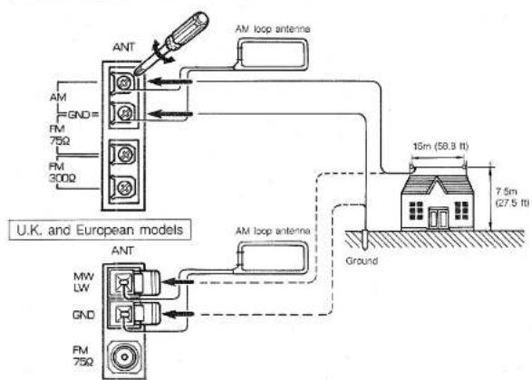
- Connecting an outdoor AM antenna:
If good reception of radio broadcasts cannot be obtained with the included antennas, use an outdoor antenna.
Regarding setup and attachment of an outdoor antenna, inquire with your dealer.
AM antenna
String an antenna approximately 15 meters (58.8 ft.) long and 7.5 meters (27.5 ft.) high either on your roof or above the ground using poles.
Connecting a ground lead will further increase sensitivity. Notes: (1) In this case leave the loop antenna connected.
(2) Do not attach the ground lead to a gas pipe. It could cause sparks which might set of an explosion.
U.S.A., Canadian, Australian and Regular models
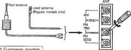
3. Connecting the included FM antenna:
U.S.A., Canadian, Australian, and Regular models
Attach the included FM rod antenna to the rear panel. Use a Phillips-head screw-driver to connect the antenna leads to the FM 75Ω terminals.
U.K. and European models
Insert the antenna plug into the center hole of the FM connector.
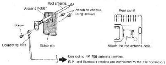
- Attaching the rod antenna (U.S.A., Canadian, Australian, U.K. and European—except German and Italian—models only)
Assemble the antenna holder, rod antenna and connecting lead as shown in the diagram and affix them to the unit using the screws provided. Connect the other end of the connecting lead to the FM 75Ω antenna terminal.
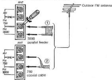
5. Connecting an external FM antenna:
U.S.A., Canadian, Australian, and Regular models
① Attach 300Ω parallel feeder antenna leads to the FM 300Ω terminals.
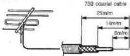
② For a 75Ω coaxial cable, connect the cable core to the FM 75Ω terminal and the braided conductor to the GND terminal.
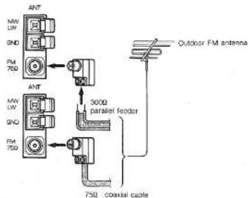
U.K. and European models
Connect the antenna leads to the included converter plug (75/300Ω) and plug into the FM connector.
flowchart
graph TD
    A["ANT"] --> B["75Ω"]
    C["ANT"] --> D["300Ω parallel feeder"]
    E["75Ω"] --> F["Coaxial cable"]
    G["Outdoor FM antenna"] --> H["Ant"]
    I["75Ω"] --> J["Ant"]
    K["Ant"] --> L["75Ω"]
    M["Ant"] --> N["Ant"]
Using the convertor plug (U.K. and European models):
• 300Ω parallel feeder antenna cable
① Remove the insulation from the end of the cable to reveal about 15 mm (9/16") of the conductors and twist the exposed strands.
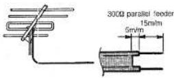
② Loosen the screws on the converter plug and insert the exposed feeder wires.
③ Tighten the screws to secure the feeder wires.
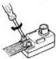
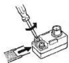
- 75Ω coaxial antenna cable
① Press the end of the coaxial cable as shown in the illustration.
⑤ Replace the cover.
② Pinch the hooks inward and remove the cover.

③ Sever the red lead using a wire cutter.

④ Insert the end of the coaxial cable into the slip in the pin as shown. Next, use a small pliers to crimp the metal fitting so that is secures the braided insulation.

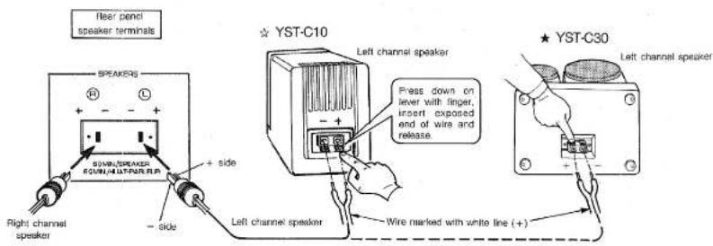
■ SPEAKER SYSTEM CONNECTIONS
CAUTION This unit is equipped with the newly developed Active Servo Processing Speakers. Therefore, the utmost performance will be obtained only by connecting the provided speakers such as YST-SC30 or YST-SC10.
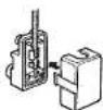
Connect the speakers attached to the main unit and the rear panel speaker terminals using the speaker cables provided. Plug the speaker cable connector into the appropriate rear panel speaker terminal. Connect the other end of the cable to the speaker as follows: connect the wire marked with a white line to the positive (+) terminal and the wire with no white line to the negative (−) terminal.
Take care not to reverse the (L) left and (R) right channels when making connections.
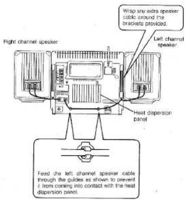
■ EXTRA SPEAKER CABLE
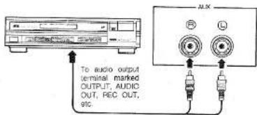
■ CONNECTING EXTERNAL COMPONENTS
Connect the output terminals of external AV components (such as the OUTPUT terminal of a radio-cassette player or the AUDIO OUT terminals of a VCR) to the AUX input terminals on the rear of the unit using pin jack connector cables.
Notes:
(1) Turn power to all components off before making connections.
(2) Take care not to reverse the (L) left and (R) right channels when making connections.
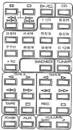
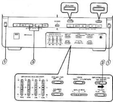
NAMES AND FUNCTIONS OF PARTS
Fig. 1 REAR PANEL
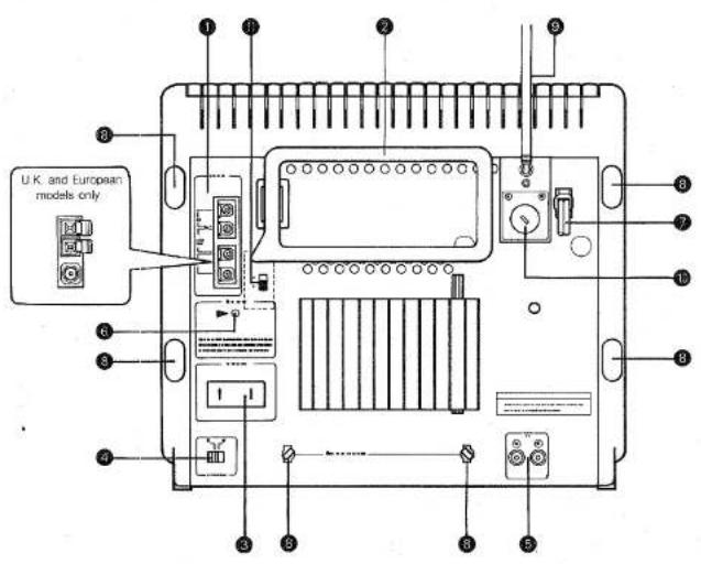
1 Antenna terminals
AM (or MW/LW: U.K. and European models only) terminal
Ground terminal
FM75Ω terminal: U.S.A, Canadian, Australian
and Regular models only
FM300Ω terminal: U.S.A, Canadian, Australian and Regular models only
② Loop antenna
3 Speaker terminals
BEAT CANCEL switch
⑤ AUX input terminal
⑥ Memory reset button
To erase the entire contents of the memory or if the display is not operating properly, unplug the unit's AC power cord and hold down this button for approximately one minute.
⑦ AC power cord
8 Brackets for excess speaker cable
⑨ Rod Antenna (except German, Italian and Regular models)
⑩ Voltage selector (Regular models only)
⑪ AM. frequency selector switch (Regular models only)
Notes: (1) The display shows information appropriate to the operation selected.
(2) All illustrations show the YST-C30.
(3) The YST-C10 lacks the CD direct play buttons, BALANCE control and EQ REC button.
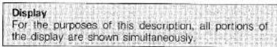
Fig. 2 TUNER/AMPLIFIER SECTION
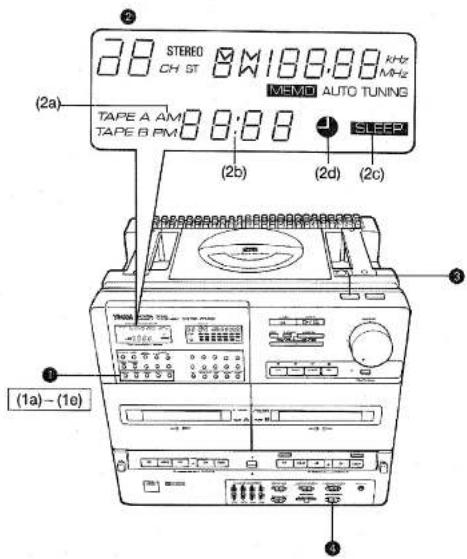
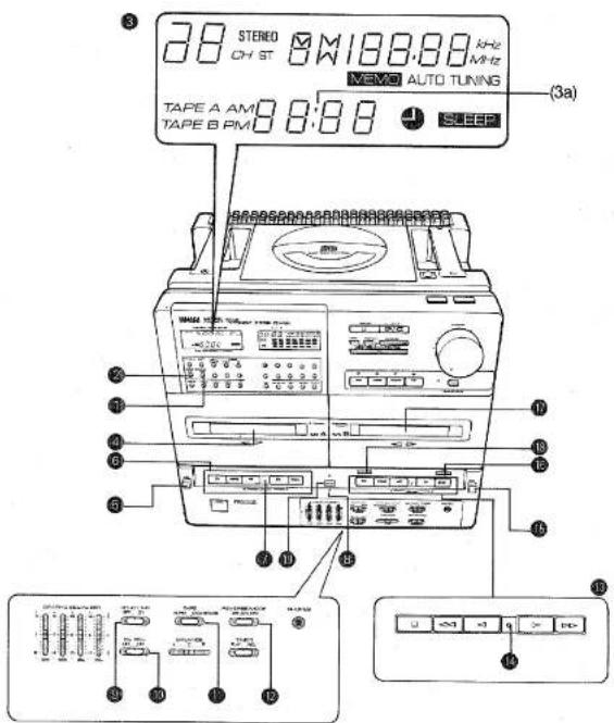
Fig. 3 TIMER SECTION
■ TUNER/AMPLIFIER SECTION (See Fig. 2)
# Display (tuner section)
(1a) TUNING indicator
(1b) MEMO (MEMORY) indicator
(1c) AUTO tuning indicator
(1d) BAND indicator
(1e) Frequency display
(1f) ST (STEREO) indicator
(1g) STEREO (STEREO MODE) indicator
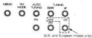
② Station selector buttons (See page 17.)
Press to select between the FM and AM (or MW/LW: U.K. and European models only) bands.
(2a) MEMO (MEMORY) button
Press to record the currently tuned in station frequency in memory.
(2b) FM MODE button
Press to choose between the stereo and monaural modes for FM broadcasts.
(2c) AUTO TUNING button
Press this button followed by the TUNING button to select stations automatically.
(2d) TUNING (UP, DOWN) buttons
Press the UP and DOWN buttons as appropriate to tune in the desired station frequency. (2e) FM button
(2f) AM (or MW and LW: U.K. and European models only) button
③ Input selectors/indicators
Press the appropriate button to select between the CD, TUNER, TAPE and AUX (external component) input sources. When a button is pressed the corresponding indicator lights.
4 POWER switch
Press to turn power on. Press a second time to turn power off.
Notes on Stand-by mode:
When the POWER switch of the unit or the POWER button on the remote control transmitter is pressed to turn off the power, the display panel remains dimly lit.
To completely turn off the power, be sure to pull out the power plug from the AC outlet.
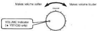
⑤ VOLUME knob/indicator (★ YST-C30 only)
⑤ DYNAMIC SOUND button/indicator
7 REMOTE CONTROL photo sensor
8 Fold-out legs
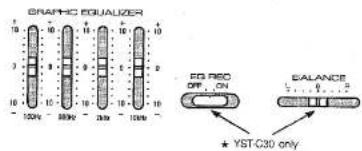
9 GRAPHIC EQUALIZER sliders
⑪ BALANCE control slider (★ YST-C30 only) Use to adjust the balance of the left and right channels. The slider can usually be left in the center "0" position.
PHONES jack
■ TIMER SECTION (See Fig. 2)
Timer setting buttons (See page 26.)
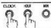
(1a) TIMER button
Press the HOUR and MIN buttons as appropriate while holding down this button to set the timer ON time.
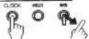
(1b) SLEEP button Press the HOUR and MIN buttons as appropriate while holding down this button to set the sleep time.
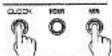
(1c) CLOCK button
Press the HOUR and MIN buttons as appropriate while holding down this button to set current time. This button is also used to switch between the tape counter and current time displays.
(1d) HOUR button
(1e) MIN button
② Display (timer section)
(2a) AM, PM indicators (does not function on U.K. and European models which use a 24-hour time indication)
(2b) Time display
(2c) SLEEP indicator
(2d) TIMER indicator
③ TIMER (TIMER/SLEEP) SET switch
4 TIMER MODE switch
TO CONFIRM TIMER SETTINGS
- Press the TIMER button to check the timer ON setting.
- Press the SLEEP button to check the sleep time setting.
Fig. 4 CD PLAYER SECTION
Fig. 6 CASSETTE DECK SECTION
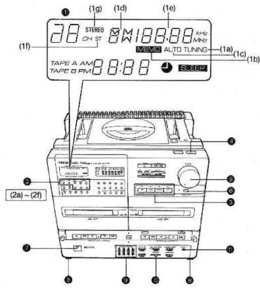
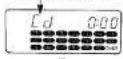
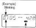
Display For the purposes of this description, all portions of the display are shown simultaneously.
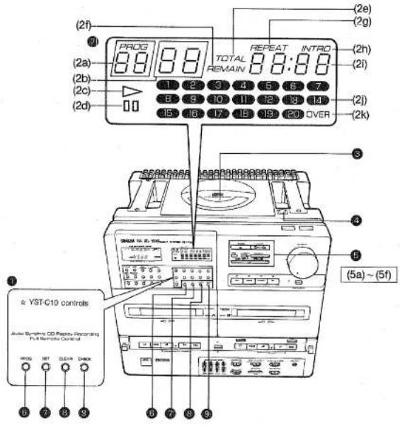
■ CD PLAYER SECTION (See Fig. 4)
① Direct play buttons (★ YST-C30 only)
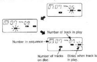
② CD display
(2a) PROG (PROGRAM) indicator
(2b) Track Indicator
(2c) ▷ PLAY indicator
(2d) ☐ Pause indicator
(2e) TOTAL time indicator
(2f) REMAIN time indicator
(2g) REPEAT indicator
(2h) INTRO indicator
(2i) Playing time display
(2j) Music calendar
(2k) OVER indicator
③ Disc holder
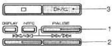
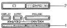
CD eject button
CD play buttons
(5a) □ (stop) button
Press to stop disc play.
Disc play stops automatically when the end of
the CD is reached.
(5b) ▷/⊂ PLAY/REPEAT button
Press to play a CD. Press twice for repeat play.
(5c) DISPLAY button
Press to change the playing time display mode.
(5d) INTRO button
Press to initiate the intro play function.
(5e) PAUSE button
Press to stop disc play temporarily.
Play resumes when the ▷/c button is
pressed.
(5f) <</<<->>/>> (skip/search) buttons
Use these buttons to start play from the begin-
ning of a specific track, to skip over a track
(or tracks) or to search while paused.
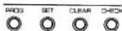
⑥ PROG (PROGRAM) button
SET button
CLEAR button
⑨ CHECK button
The above 6\~9 buttons are used for programmed
play.
■ CASSETTE DECK SECTION (See Fig. 1)
TAPE COUNTER RESET button
Press to reset the tape counter to "0000."
2 TAPE COUNTER CALL button
Press to switch the display from the current time
to the tape counter indication. Subsequent presses
toggle between TAPE A and TAPE B counter indica-
tions:
③ Display (tape section)
(3a) Tape counter
Cassette holder (TAPE A)
⑤ EJECT button (TAPE A)
Operation buttons (TAPE A)
□ (stop) button
<=(rewind) button
◀ (play) button/DIRECTION indicator
▷ (play) button/DIRECTION indicator
( fast forward) button
⑦ TAPE A PLAY indicator
REC (recording) indicator
⑨ DOLBY NR switch
13 EQ REC (equalizer recording) switch
(★ YST-C30 only)
10 TAPE selector switch
19 REVERSE MODE switch
13 Operation buttons (TAPE B)
Same as above.
TAPE B PLAY indicator
(Blinks during PAUSE.)
EJECT button (TAPE B)
REC (recording) button
Note: Press to make a recording.
The replay function (an editing function which
prevents the sound from being interrupted
when the tape switches directions) is ac-
tivated when recording from CD.
Cassette holder (TAPE B)
12 PAUSE button
DUBBING button/indicator
REMOTE CONTROL
Notes: (1) The remote control may not work properly if there is anything blocking the photo sensor.
(2) Do not bump or drop the remote control. Also take care not to get it wet or leave it in excessively hot places.
(3) The remote control may not work properly if the photo sensor is exposed to direct sunlight or bright room lighting. If this happens, alter the placement of the light or the unit.
(4) Commands from the remote control may not register if it is used at the same time as the infrared remote control unit of another component or appliance.
(5) The effective range of the remote control extends approximately 20° to the right and left of a straight line perpendicular to the photo sensor. The optimum distance is anywhere between approximately 30 cm (11-13/16") - 6 m (23.6 ft.) from the sensor.
(6) Never connect (short) the (+) and (−) terminals directly with a metal piece, wire etc.
(7) When inserting batteries align their (+) and (−) poles as indicated in the battery compartment.
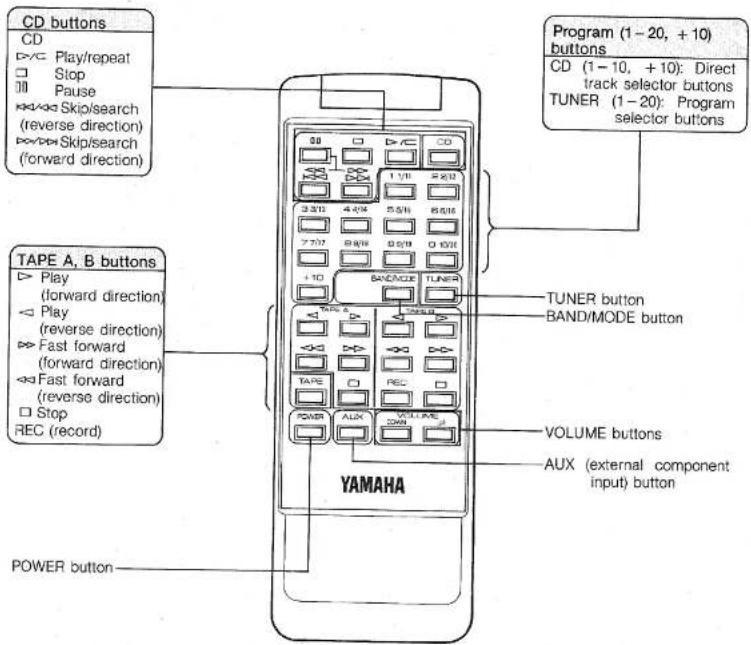
■ REMOTE CONTROL OPERATION
The remote control is capable of performing the following functions:
Input selector: Switching between CD, TAPE, TUNER and AUX (external component) input
CD: Play/Repeat, skip, search, direct track selection, pause and stop
TUNER: Program selection, band (FM/AM or FM/MW/LW: U.K. and European models only) switching and mode (monaural/stereo) switching
TAPE: Play, fast forward, record and stop
VOLUME: Up and down
POWER: ON/OFF
■ REMOTE CONTROL NUMERIC KEYPAD
CD: Press the button corresponding to the number of the desired track to start play directly from that track. For tracks 10 and above the [+10] key is used. For example, to select track 15 you would press [+10] followed by [5].
TUNER: The number keys function as preset station selector buttons. Up to 20 FM stations can be preset in memory. The following method is used both for setting and recalling stations:
1/11 Press once for preset station number 1 Press twice for preset station number 11
2/12 Press once for preset station number 2 Press twice for preset station number 12
10/20 Press once for preset station number 10 Press twice for preset station number 20 Up to 10 AM (or MW/LW; U.K. and European models only) stations can be preset in memory.
(MW/LW stations can be assigned to any of numbers from 1 to 10 as you see fit.)
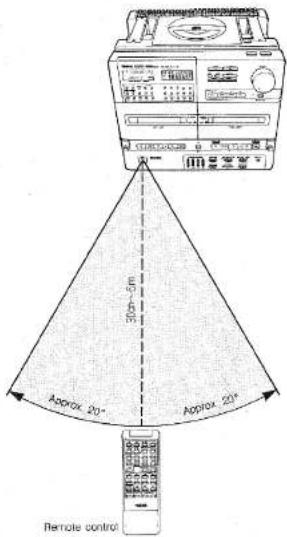
The effective range of the remote control extends approximately 20° to the right and left of a straight line perpendicular to the photo sensor. The optimum distance is anywhere between approximately 30 cm (11-13/16")—6 m (23.6 ft.) from the sensor.
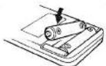
■ BATTERY INSTALLATION AND REPLACEMENT
When the remote control operating distance becomes short, the batteries are weak. Replace the old batteries with new ones. Incorrect use of a batterie may cause leakage or an explosion. Be careful of the following items:
- Replace only with "AAA" (UM-4) batteries.
- Do not use an old battery with a new one.
- Do not use different kinds of batteries (alkaline, heavy duty, manganese, Ni-Cd, etc.) at the same time.
- In case of leakage, wipe off the electrolyte in the battery compartment completely before installing new batteries.
① Remove the rear cover as shown.

② Insert new batteries.
③ Replace the rear cover.
VOLUME AND TONE ADJUSTMENTS
■ ADJUSTING THE VOLUME
Turn the volume knob to adjust the volume.
■ LISTENING AT LOW VOLUME
Press the DYNAMIC SOUND button.
This causes the low and high frequencies to be adjusted to create plenty of listening excitement even at low volume levels.
Note: All graphic equalizer sliders should be set to "0" when using the DYNAMIC SOUND button.
■ ADJUSTING THE VOLUME USING THE REMOTE CONTROL
Press the UP and DOWN VOLUME buttons as appropriate. The volume increases when UP is pressed and decreases when DOWN is pressed.
Notes: (1) Hold the button down and the volume continues to change.
(2) On the main unit, the VOLUME indicator (★ YST-C30 only) blinks and the VOLUME knob moves automatically.
■ LISTENING WITH HEADPHONES
Plug the headphones into the PHONES jack.
Notes: (1) Use headphones with an impedance of 8–32Ω and equipped with a mini-plug 3.5 mm (2/8") in diameter.
(2) No signal is output to the speakers when headphones are connected.
■ ADJUSTING THE TONE
Use the graphic equalizer sliders to adjust the tone. Move a slider up or down as appropriate to adjust the frequencies close to the slider's center frequency. (Move the slider up to emphasize the sound and down to attenuate it.)
The graphic equalizer functions as follows:
☆ On the YST-C10, it functions only during play.
★ On the YST-C30, it functions during recording as well if the EQ REC button is in the ON position.
LISTENING TO RADIO BROADCAST
For Regular models: Before attempting to tune in stations set the AM frequency selector switch on the rear panel to the 9 kHz or 10 kHz position as appropriate for your area.
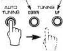
■ AUTO STATION SELECTION
The auto station selection function scans the available bands and stops when it comes to a frequency on which a signal is being broadcast. The tuned in station frequency or channel number appears on the display. (See page 30, "SPECIFICATIONS.")

Press the POWER switch.

Press the TUNER button.

Choose a band:
* FM: to listen to FM broadcasts
* AM (or MW: U.K. and European models only); to listen to AM broadcasts
* LW: to listen to long wave broadcasts (U.K. and European models only)
To listen to an FM broadcast, press the FM MODE button. The stereo mode indicator lights. When a stereo broadcast is being received the ST (STEREO) indicator lights.

Press the auto tuning button followed by either the UP or DOWN TUNING button. The tuner searches for a station and stops automatically when it finds one.
DOWN: Frequency decreases UP: Frequency increases
Notes: (1) To continue searching for another station, press one of the TUNING buttons again.
(2) In the stereo mode the STEREO (STEREO MODE) indicator lights. If a FM station is tuned in, the ST (STEREO) indicator lights when a stereo broadcast is being received.
(3) When a station has been tuned in the TUNING indicator lights and auto search stops.
■ MANUAL STATION SELECTION
Press on the UP or DOWN TUNING buttons when the AUTO indicator is not lit to move one frequency step at a time in the desired direction. This operation is called manual station selection.
• The station frequency display
Remains when an input selector other than TUNER has been selected. Nevertheless, station selection will not operate in this condition. Always press the TUNER button before attempting station selection.
■ PROGRAMMING THE MEMORY
1 Select a broadcast using "AUTO STATION SELEC-TION" STEPS ⑦ - ④.
2 Press the MEMO button followed by the remote control program key. The MEMO and PROGRAM indicators blink.
3 Press the MEMO button a second time. The PROGRAM indicator now remains lit continuously.
Repeat STEPS ① - ③ above to preset other stations. Up to 20 FM stations and 10 AM (or MW/LW: U.K. and European models only) stations (a total of 30 stations) can be preset.
- Changing the stations programmed in memory
Follow STEPS ① - ② above to program a new station. The old station is erased automatically.
■ SELECTING A PRESET STATION
1 Choose a band (the remote control BAND/MODE button can also be used):
* FM: to listen to FM broadcasts
* AM (or MW: U.K. and European models only) : to listen to AM broadcasts
• LW: to listen to long wave broadcasts (U.K. and European models only)
2 Press the button corresponding to the desired preset number.
- Listening to FM stereo broadcasts
Press the FM MODE button. The STEREO (STEREO MODE) indicator lights.
The FM mode can also be preset when the station is programmed.
Note: When listening to very weak stations in the stereo mode, the muting function may sometimes make them inaudible.
NOTES ABOUT HANDLING COMPACT DISCS
- This compact-disc player is designed only for reproduction of compact discs bearing the mark. Never attempt to load any other type of disc into the unit. The unit will also play 8 cm (3 inch) compact discs.
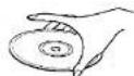
- To remove a disc from its storage case, open the case and then press down at the center; with a finger through the center hole and the outer edges held as shown in the illustration, lift the disc out carefully.

● Always handle the disc with care so that its surface is not scratched.
- Compact discs are not subjected to wear during play, but damage to the disc surface when the disc is being handled can adversely affect the disc's play.
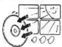
- Compact discs are not affected by small particles of dust or fingerprints on their playing surface, but even so they should be kept clean. Wipe by using a clean, dry cloth. Do not wipe with a circular motion; wipe straight outward from the center.

- Do not try to clean the disc's surface by using any type of disc cleaner, record spray, anti-static spray or liquid, or any other chemical-based liquid, because such substances might irreparaly damage the disc's surface.
- Do not expose discs to direct sunlight, high temperature or high humidity for a long period of time, because these might warp or otherwise damage the discs.
PLAYING COMPACT DISCS
■ PLAY AND BASIC OPERATIONS
First turn the POWER switch on.

Press the CD button. The CD display lights.
GD display blinks


Press the 🔒 button. Insert a CD.

Close the cover.
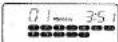
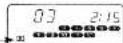
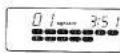
—The number of tracks on the CD and the total playing time are displayed.
The numbers on the music calendar corresponding to the number of tracks on the CD light.
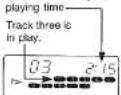
—After approximately four seconds "01" is displayed along with the playing time for the first track.
CD display blinks

(Example) 12 tracks

(Example) 12 tracks

Press the ▷/⊆ (play/repeat) button.
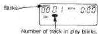
—The ▶ indicator blinks while the player searches for the beginning of the first track.
—The ▷ indicator lights continuously when the beginning of the first track is located. The elapsed playing time for the current track is also displayed.
—After the playback of the last track no. has finished the music calendar display goes out.
—When the track finishes playing, its number goes out.
Play indicator
blinks.
Current track elapsed
PAUSING PLAY
Press the PAUSE button. Play pauses at the point at which the button was pressed.
Press the ▶/▽ (play/repeat) button to resume play.
ights
STOPPING PLAY
Press the □ button.
Notes: (1) In order to eject a CD which is still playing, first press the □ button. Once you have made sure that play her stamped press the ○ button
(2) Playing CDs may cause interference with nearby tuners or TV sets. This is the liable to happen particularly with tuners or TV sets which use an indoor antenna. Switching to an outdoor antenna is recommended.
(3) Exposing the unit to bumps or vibrations may cause skipping during playback. Some CDs containing very loud sections may also be prone to skipping. Should this problem occur, lower the volume.
(4) Do not press the 🔒 button while a CD is playing.
MUSIC CALENDAR
When a disc is loaded into the disc holder, the numbers on the music calendar corresponding to the number of tracks on the CD appear.
As each track finishes playing, its number goes out. When program track selection is used, the numbers of the programmed tracks appear. This allows you to confirm that they are programmed correctly before playing the sequence.
Lights, then goes out when track finished playing.
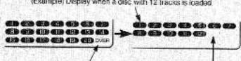
"OVER": Lights when a disc with more than 20 tracks is loaded. Track numbers not on the disc do not light.
■ PROGRAMMING TRACKS
This function is for listening to selected tracks in the order of your choice.

(Example)
Load a CD by following "PLAY AND BASIC OPERATIONS" STEPS ① - ②

(Example) Blinking.
When the CD is not in play, press the PROG button. —A track number display identical to the music calendar appears, blinking.
Blinking.

(Example) Blinking.
Press a direct play button to select a track number.
☆ For the YST-C10, use the remote control keys.
★ For the YST-C30, use either the main unit control panel or the remote control keys.
(Example) Blinks when track five is selected.

Press the SET button.
Repeat STEPS Ⓞ - Ⓥ as many times as necessary to program the desired track sequence in memory (up to a maximum of 20 tracks).
Number in program sequence.
■ PROGRAM PLAY
Press the P/C (play/repeat) button. The programmed track sequence is played in order.
Note: Pressing the × or × button during play causes play to continue at the beginning of the next (or current) track.
TO CHECK THE ORDER OF TRACKS
When the CD is not in play, press the CHECK button. (Example) Display when the track sequence 5→9→7 has been programmed.
Notes: (1) If the CHECK button is pressed during play or when play is paused, the number of the next track to be played is displayed for approximately two seconds.
(2) If the CHECK button is pressed when the last track in the sequence is in play, "End" is displayed.
CANCELING THE CURRENT PROGRAM
Press the CLEAR button when the disc is not playing (and the PROG indicator is lit). All programmed tracks are canceled.
Notes: (1) Press the CLEAR button during programming (when the PROG indicator is blinking) to cancel only the last track programmed.
(2) Tracks can be neither programmed nor canceled during play or when play is paused.
DISCS CONTAINING MORE THAN 20 TRACKS
"OVER" appears on the display if a disc containing more than 20 tracks is loaded. Even if "OVER" is displayed, play operations operate exactly the same as with discs containing 20 tracks or less except that the playing time is not displayed. For programming, press the +10 button followed by 1 - 9, as appropriate. (Example) The following sequence would be used for
+10→+10→4
■ SEARCHING FOR A PARTICULAR PASSAGE WHILE LISTENING TO THE MATERIAL ON THE DISC AT HIGH SPEED (SEARCH)
-
Press the PAUSE button during play.
-
Press the or button.
-
Press thet>/=(play/repeat) button at the place you wish to listen to. Play begins.
• How the search function operates
When search commences, playback is at twice normal speed for approximately two seconds, then switching to 15 times normal speed. Output continues at reduced volume during the search to assist you in finding the desired place on the disc.
- "End" display
If the end of the disc is reached during search operation, "End" appears in the display. Should this happen, press the □□ button. Note: The search function does not operate during program play or intro play.
■ LISTENING FROM THE BEGINNING OF A DESIRED TRACK (SKIP)
When the CD is not playing, press the (to move to a lower track number) or key (to move to a higher track number) as appropriate to move to the desired track.
- Press the ▷/⊂ (play/repeat) button. Play begins.
• To skip over more than one track
Press the K or D key as appropriate as many times as necessary. Play will begin from the track number displayed.
■ LISTENING FROM A SPECIFIC TRACK (DIRECT PLAY)
Press one of the direct play buttons on the remote control or on the control panel. The track selected starts playing.
☆ On the YST-C10, use the direct play buttons on the remote control.
★ On the YST-C30, use the direct play buttons on the remote control or on the control panel.
■ REPEAT PLAY
REPEATING THE ENTIRE DISC
Press the ▶/▽ (play/repeat) button twice. The REPEAT indicator lights. After the last track finishes playing, play continues with the very first track.
REPEATING A PROGRAMMED SEQUENCE OF TRACKS

Follow the instructions under "PROGRAMMING TRACKS" (See page 19.) to program a single track or as many as you desire.

Press the D > / G (play/repeat) button twice. The REPEAT indicator lights.
Note: After the last track in the sequence finishes playing, play continues with the very first track.
STOPPING REPEAT PLAY
Press the t > / = (play/repeat) button. The REPEAT indicator goes out.
Note: Normal play continues.
■ LISTENING TO THE FIRST PART OF EACH TRACK ON THE DISC (INTRO PLAY)
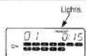
This function enables the first 15 seconds of each track on the CD to be played automatically.
Press the INTRO button. The INTRO Indicator lights. —Intro play begins, starting with the first track on the disc. (After the first 15 seconds is played, intro play continues with the next track on the disc, and so on until the last track is reached.)
(Example)
Notes:
(1) Play stops automatically after the beginning of the last track on the disc has been played.
(2) Intro play and repeat play cannot be combined
STOPPING INTRO PLAY
Press the ▷/▽ (play/repeat) button
—The INTRO indicator goes out and normal play continues.
■ PROGRAMMING THE MEMORY DURING INTRO PLAY (INTRO PROGRAM SELECTION)
You can select tracks for the programmed memory sequence as you listen to them.

Press the INTRO button. Intro play begins.

Press the PROG button.


While a track you wish to program is playing, press the SET button.
Notes: (1) Intro play continues with the next track after the SET button is pressed.
(2) Play stops automatically after the beginning of the last track on the disc has been played.
(3) The D/C (play/repeat) button has no effect when the intro program function is operating.
STOPPING INTRO PROGRAM SELECTION
Press the □ button.
—The INTRO indication goes out and intro program selection stops. The programmed track numbers remain in memory.
■ DISPLAY FUNCTIONS
The display time indication changes as follows when the DISPLAY button is pressed.
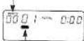
WHEN NO CD IS PLAYING
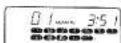
The playing time of each track is displayed. Press the RAC/03 or 00/05 button to change the number of the track being displayed.
(Example)
If track seven is 2 minutes and 58 seconds long:
—The playing time of the individual track is displayed.
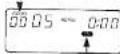
(Example)
If the amount of time from the beginning of the CD to the end of track seven is 26 minutes and 30 seconds:
—The total playing time from the beginning of the CD to the end of track seven is displayed.
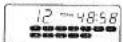
DURING PLAY
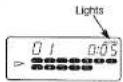
(Example)
If eight seconds have elapsed since the beginning of track two:—The elapsed time for the track in play is displayed.
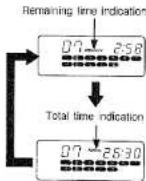
(Example)
If 2 minutes and 58 seconds remain before the end of track two:—The remaining time of the individual track is displayed.
(Example)
If 41 minutes remain before the end of the CD:
—The total playing time from the current point on the disc to the end is displayed.
DISCS CONTAINING MORE THAN 20 TRACKS
“-:-” “OVER” is displayed.
(Example)

Notes:
(1) The playing times listed on the cases of some CDs may not include the gaps between tracks. This can sometimes give rise to discrepancies between the time listed on the case and the time appearing on the display.
(2) No time indication will appear in the following cases if a CD containing more than 20 tracks is loaded.
1. If a track number higher than 20 is displayed when the CD is not playing.
2. If you try to display the remaining time while a track number higher than 20 is playing.
3. If a track number higher than 20 is programmed in the memory sequence. (There is also no time display if the total playing time of the programmed tracks exceeds 100 minutes.)
NOTES ABOUT HANDLING CASSETTE TAPES
There are many different types of cassette tapes available, however, they all conform to standard specifications so any brand may be used with the deck.
Note: However, YAMAHA does not recommend the use of 120 minute length cassettes since the extreme thinness of the tape makes them susceptible to mechanical and recording problems.
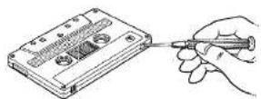
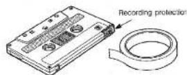
• Protecting your recordings
All cassette tapes are provided with erasure prevention holes to prevent accidental erasure of recorded contents. There is a small tab covering the hole on each cassette, and it should be broken off after recording a tape. Without this tab covering the hole, it is impossible to record onto that tape. Thus, you can safely protect a recording for as long as you wish without fear of accidental erasure. Should you wish to use a cassette tape protected in this way for recording, simply covering the hole with adhesive tape will permit erasure and re-recording.
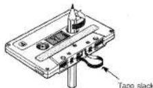
- Taking up slack in the tape
As a precaution against tape entanglement and damage, before inserting cassettes into this unit, move any slack in the tape. This is accomplished by inserting a pencil, pen or similar object into one of the spools and gently winding it until all the slack is removed. You do not have to wind it too tightly. Be careful not to touch the tape part itself. It is very delicate and touching it may damage the tape and its recorded contents.
- Storing cassettes
After putting a cassette tape back into its case, store in a location away from exposure to direct sunlight, humidity, high temperatures, and magnetic fields (away from television sets, speakers, etc.). High temperatures and humidity will damage the tape itself, while exposure to magnetic fields may cause a loss of recorded material. Avoid touching the tape surface with your fingers, since dirt or finger oil will contaminate the deck's heads.
CASSETTE TAPE PLAY
First set the POWER switch to ON.
1 Press the TAPE button.
2 Press the TAPE A or the TAPE B EJECT button. Insert a cassette and close the door of the cassette holder.
3 Move the TAPE selector switch to the appropriate position.
| CrO2/METAL (PB) | Position for metal and chrome tapes |
| NORM | Position for normal tapes |
Notes: (1) The TAPE selector switch affects both TAPE A and TAPE B.
4 Move the DOLBY NR switch to the appropriate position.
Note: Set to ON to record using the Dolby NR system (Dolby B).
5 Move the REVERSE MODE selector switch to the appropriate position.
| Plays one side only. | |
| Plays both sides. | |
| Plays both sides repeatedly. |
Note: If cassettes are inserted in both the TAPE A and TAPE B holders, continuous play
(→TAPE A→TAPE B) is possible only if the REVERSE MODE switch is set to ⇌.
(See page 23 "REVERSE MODE AND CONTINUOUS PLAY".)
6 Press the < or > button of the deck in which the cassette to be played is inserted. Play begins.
STOPPING TAPE PLAY
Press the □ button
Notes: (1) Do not press more than one control button at once, as it could cause the unit to malfunction. (2) Press buttons slowly and firmly. If the deck does not respond correctly, try pressing the button again.
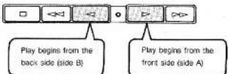
■ SEARCHING FOR THE BEGINNING OF A SELECTION (FIND BEGINNING PLAY)
You can skip from the selection in play to the beginning of the selection immediately preceding or following it. (Operation is the same for both TAPE A and TAPE B.)
① When the front side (side A) is in play:
Press to skip back to beginning
of selection currently in play
Press to skip to beginning of
next selection.
② When the back side (side B) is in play:
Press to skip to beginning of
next selection.
Press to skip back to beginning
of selection currently in play.
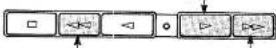
■ SKIPPING BACK TO THE BEGINNING OF THE SELECTION CURRENTLY IN PLAY
- Skipping by pressing the fast forward button corresponding to the direction of tape play
Press once to skip one selection ahead. Press twice to skip two selections ahead. Press three times to skip three selections ahead. Press four times to skip one selection ahead. (and so on)
- Skipping by pressing the fast forward button opposite the direction of tape play
Press once to skip to beginning of current selection Press twice to skip one selection back. Press three times to skip two selections back. Press four times to skip to beginning of current selection. (and so on)
Notes on the skip function:
The skip functions works by detecting blank spaces of about 4 seconds length between selections on the tape. Therefore, in case of the following the skip function might not work properly.
-
If there is conversation, narration or sound between selections.
-
If the overall recording level of a selection is too low (sound is too low).
-
If the blank space between selections is 3 seconds or less.
-
If selections contain very low passages (very low volume) of music, long breaks or unrecorded parts.
- If there is noise or hum between selections.
(2) If you try to skip from the very beginning or end of a selection, the tape might not stop at the next or previous selection.
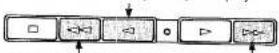
■ FAST FORWARD/REWIND
Press the <= or <<> button when the tape is stopped. Press the □ button when the point on the tape you wish to listen to is reached.
Press to wind tape onto the reel on the left
Press to wind tape onto the reel on the right.
■ REVERSE MODE AND CONTINUOUS PLAY
Continuous play is possible if cassettes have been inserted in both the TAPE A and TAPE B cassette holders. The following repeat modes can be accessed by using the REVERSE MODE switch.
- If tape play switches from TAPE A to TAPE B or from TAPE B to TAPE A, play automatically commences on the new cassette in the direction indicated by whichever DIRECTION indicator is lit.
- You can set the REVERSE MODE switch either before or during play.
- If the REVERSE MODE switch is set to ⇔, play will continue indefinitely or until the □ button is pressed.
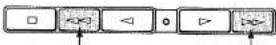
CONTINUOUS PLAY USING BOTH TAPE A AND TAPE B

Insert cassettes in both the TAPE A and TAPE B cassette holders.

Set the REVERSE MODE switch to

Press one of the < " > buttons.
- If the ▷ button of TAPE A is pressed:
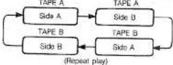
- If the < button of TAPE A is pressed;
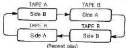
Note: The procedure is the same for TAPE B.
RECORDING
■ RECORDING FM/AM OR FM/MW/LW (U.K. AND EUROPEAN MODELS ONLY) BROADCASTS
THE BEAT CANCEL SWITCH
(See pos)

Note: If "beat" interference (a high pitched tone) is audible when recording AM (or MW/LW, U.K. and European models only) radio broadcasts, set the BEAT CANCEL switch on the rear panel to position "A" or "B" at which the beat interference is least prominent.
1
Press the TUNER input selector button.
2
Tune in a station on the radio. (See page 18.)
3
Insert a cassette tape in the TAPE B cassette holder.
Note: Make sure the erasure prevention tab for the side to be recorded is not broken off.
4
Move the DOLBY NR switch to the appropriate position.
Note: Set to ON to record using the Dolby NR system (Dolby B).
5
Move the TAPE selector switch to the appropriate position.
| CrO2/METAL (PB) | Position for chrome tapes |
| NORM | Position for normal tapes |
Note: Metal tapes can not be used for recording.
6
Move the REVERSE MODE selector switch to the appropriate position.
| Records one side only. | |
| Records both sides. |

Press the REC (record) button. The REC indicator lights.

Press the < or ▷ button, depending on the recording direction. Recording begins.
TO TEMPORARILY PAUSE RECORDING
To temporarily pause recording, press the PAUSE button. Tape stops at the point where PAUSE was pressed. To recommence recording, press the => button corresponding to the recording direction.
TO STOP RECORDING
Press the □ button.
TO MONITOR THE SIGNAL BEING RECORDED
You can listen to the signal being recorded through the speakers or with headphones. Use the VOLUME knob to adjust the listening volume.
THE TAPE COUNTER
The tape counter can be a valuable reference when recording tapes.
- Use the TAPE COUNTER CALL button to switch the tape counter between TAPE A and TAPE B indications.
- Use the TAPE COUNTER RESET button to reset the TAPE A or TAPE B counter, whichever has been selected (TAPE B in this case.)
Notes
(1) Press the CLOCK button to return to the current time display.
(2) The display reverts to the current time whenever the power is turned off.
(3) The tape counter is still registering when TAPE B is operating even if the current time is being displayed.
(4) If a cassette is loaded in TAPE A only, the counter switches automatically to TAPE A indication. If a cassette is loaded in TAPE B only, it switches automatically to TAPE B indication.
(5) If cassettes are loaded in TAPE A and TAPE B, the TAPE COUNTER CALL button can be used to toggle between them.
■ RECORDING FROM CD
1
Press the CD input selector button.
2
Insert the disc you wish to record.
Note: You can tailor the tracks to be recorded by programming the track playing sequence. (See page 19.)
3
Insert a cassette tape in the TAPE B cassette holder.
Notes: (1) Metal tapes can not be used for recording. (2) Make sure the erasure prevention tab for the side to be recorded is not broken off.
4
Move the DOLBY NR switch to the appropriate position
Note: Set to ON to record using the Dolby NR system.
5
Move the TAPE selector switch to the appropriate position.
| CrOx/METAL (PB) | Position for chrome tapes |
| NORM | Position for normal tapes |
Note: Metal tapes can not be used for recording.
6
Move the REVERSE MODE selector switch to the appropriate position.
| Records one side only. | |
| Records both sides. |
7
Press the REC (record) button. The REC Indicator lights. The TAPE B PLAY indicator blinks (pause mode).
8
Press the CD >/G (play/repeat) button. Tape recording begins approximately two seconds before the CD begins playing. The tape side corresponding to the lit DIRECTION indicator is recorded.
Note: If you wish to record both cassette sides, begin recording with side A.
TO TEMPORARILY PAUSE RECORDING
Press the tape PAUSE button.
Recording pauses but disc play continues.
To recommence recording, press the => button corresponding to the recording direction.
Note: The cassette deck automatically switches to the pause mode if CD play is stopped or paused.
TO STOP RECORDING
Press the tape □ (stop) button.
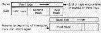
CD REPLAY RECORDING
The CD replay recording function prevents the sound of a recording from being interrupted by the tape switching sides when both cassette sides are recorded using the autoreverse function.
If the tape switches to the back side (side B) in the middle of a CD track being recorded, the CD player automatically returns to the beginning of the interrupted selection and recording continues on the back side (side B). This guarantees that the track is recorded without a break on the back side (side B).
(Example)
End of front side encountered in middle of third track
flowchart
graph TD
    A["(Tape)"] --> B["Front side"]
    B --> C["Second track"]
    C --> D["Third track"]
    D --> E["Back side"]
    E --> F["Third track"]
    G["(CD)"] --> H["First track"]
    H --> I["Second track"]
    I --> J["Third track"]
    J --> K["End of tape encountered in middle of third track"]
    L["Returns to beginning of interrupted track and starts again"] --> M["→"]
■ RECORDING FROM AN EXTERNAL COMPONENT
Recording from an external component connected to the AUX input jacks on the rear panel is possible.

Press the AUX Input selector button.

Insert a cassette tape in the TAPE B cassette holder.
Notes: (1) Metal laps can not be used for recording.
(2) Make sure the erasure prevention tab for the side to be recorded is not broken off.

Move the DOLBY NR switch and REVERSE MODE selector switch to the appropriate positions. (See page 24.)

Turn on the external component and get it ready to begin play.

Press the REC (record) button. The REC indicator lights.

Press the <1 or ▷ button corresponding to the desired recording direction. Recording begins.
TO TEMPORARILY PAUSE RECORDING
Press the tape PAUSE button. To recommence recording press the ▷ button corresponding to the recording direction.
TO STOP RECORDING
Press the tape □ (stop) button.
EQ REC (EQUALIZER RECORDING) (\*YST-C30 ONLY)
The YST-C39 allows you to record a signal which has been adjusted using the graphic equalizer. (See page 17.) To perform equalizer recording, perform the following steps before pressing the REC button in the recording procedures described in the preceding pages (pages 24–25).
1 Set the EQ REC switch to the ON position. 2 Set the graphic equalizer sliders to the desired positions.
TAPE EDITING (DUBBING)
You can make copies from the TAPE A cassette to the TAPE B cassette.
• Before starting tape editing
-
Press the TAPE COUNTER CALL button to switch the display to tape counter indication.
-
Press the TAPE COUNTER RESET button to reset the counter to "0000." This will be useful when you rewind the tape later.

Insert cassette tapes in the TAPE A and TAPE B cassette holders.
Notes: (1) Use the same type of tape for both the play-back and recording sides. (2) Metal tapes can not be used for recording.

Press the TAPE button.

Move the TAPE selector switch to the appropriate position.
| CrOx/METAL (PB) | Position for chrome tapes |
| NORM | Position for normal tapes |

Move the REVERSE MODE selector switch to the appropriate position.
| Records one side only. | |
| Records both sides. |

Press the DUBBING button. Indicator lights. Dubbing from TAPE A to TAPE B commences.
Notes: (1) Dubbing begins from the side indicated by the lit DIRECTION indicator.
(2) TAPE A and TAPE B stop together when cubbing is finished.
(3) If you stop either TAPE A or TAPE B before the end of the tape, both TAPE A and TAPE B stop together.
(4) To stop dubbing in mid course, press either the TAPE A or TAPE B □ (stop) button. TAPE A and TAPE B stop together.
■ IF THE TAPES IN THE PLAY AND THE RECORD SIDES ARE OF DIFFERENT LENGTHS
- Recording only one side: Both tape transports stop automatically when the end of the shorter tape is reached.
- Recording both sides: When the end of one of the tapes is reached, it reverses. The longer tape continues in the same direction.
- When recording with a tape in TAPE A shorter than that in TAPE B, be sure to set the REVERSE MODE switch to or . (If it is set to , recording will continue indefinitely.)
■ USING DIFFERENT TAPE TYPES FOR TAPE A AND TAPE B
Set the TAPE SELECTOR switch to match the TAPE B tape type. Note that the resulting recording will be affected as follows.
| TAPE A (playback) | TAPE B (recording) |
| Normal tape | Crame tape |
| TAPE SELECTOR switch position | |
| High frequencies muted. | |
| TAPE A (playback) | TAPE B (recording) |
| Metal/chrome tape | Normal tape |
| TAPE SELECTOR switch position | |
| High frequencies exaggerated. | |
Notes: (1) If the PAUSE button is pressed during dubbing,
both TAPE A and TAPE B pause together. Press the DUBBING button to resume dubbing.
(2) Press the □ button to stop dubbing.
(3) The following takes place automatically during dubbing.
| TAPE A (playback) | TAPE B (recording) |
| Dolby NR on | Dolby NR on |
| Dolby NR off | Dolby NR off |
USING THE TIMER
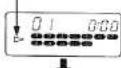
SETTING THE CURRENT TIME
- "AM12:00" (or "00:00" for U.K. and European models) appears on the current time display when the unit is first plugged in.
- The timer cannot be used unless the current time has been set.
- First, press the CLOCK button to start the clock.
Notes: (1) The timer display is as follows:
U.S.A., Canadian and Regular models use an "AM/PM" display.
"AM 12:00" = midnight
"PM 12:00" = noon
U.K. and European models use an "00:00" 24-hour display.
(2) If you make a mistake or need to reset the time, start the setting procedure again from the beginning.
(3) In case of power failure, the time is erased from the unit's memory.
When power is restored, the time display blinks to indicate that it requires resetting.

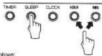
Setting the hour:
Hold down the CLOCK button and press the HOUR button. Press once to advance one hour, twice for two hours, etc.

Setting the minute:
Hold down the CLOCK button and press the MIN button. Press once to advance one minute, twice for two minutes, etc.

Starting the clock:
Hold down the CLOCK button and press and release the MIN button at the point at which you want the clock to start (0 second).
Notes: (1) The time display advances one minute and the clock starts from the 0 second point.
(2) Do not take more than one minute to set the clock. If more than one minute elapses, the minute display will advance.
SLEEP TIMER
By setting the sleep timer, you can listen to the CD player, cassette deck or radio and have them shut off automatically after a specified period of time.

Select the source you wish to listen to: Press the appropriate input selector button to prepare the source for play.

Setting the sleep timer: Hold down the SLEEP button and press the HOUR and MIN buttons as required to set the time.
Setting advances as follows:
Each time the HOUR button is pressed.

Each time the MIN button is pressed, the MINUTE display proceeds at 15-minute interval.

Note: If only the SLEEP button is pressed, the sleep timer is set to one hour automatically.

Power shuts off automatically when the set time has elapsed.
Notes: (1) Even after the sleep timer has been set, if you set the timer and press the TIMER set button, you can wake up to music the next morning. (See page 27.)
(2) When the sleep timer is operating, you can check the time remaining by pressing the SLEEP button.
(3) Press the POWER switch once to turn off the sleep function. (The sleep indicator goes out on the first press.) The power turns off on the second press.
Regarding the wake up timer operation, see page 27.
WAKE UP TIMER (TIMER PLAY) AND TIMER RECORDING
Note: First set the POWER switch to ON and check that the current time is accurate before setting the timer.
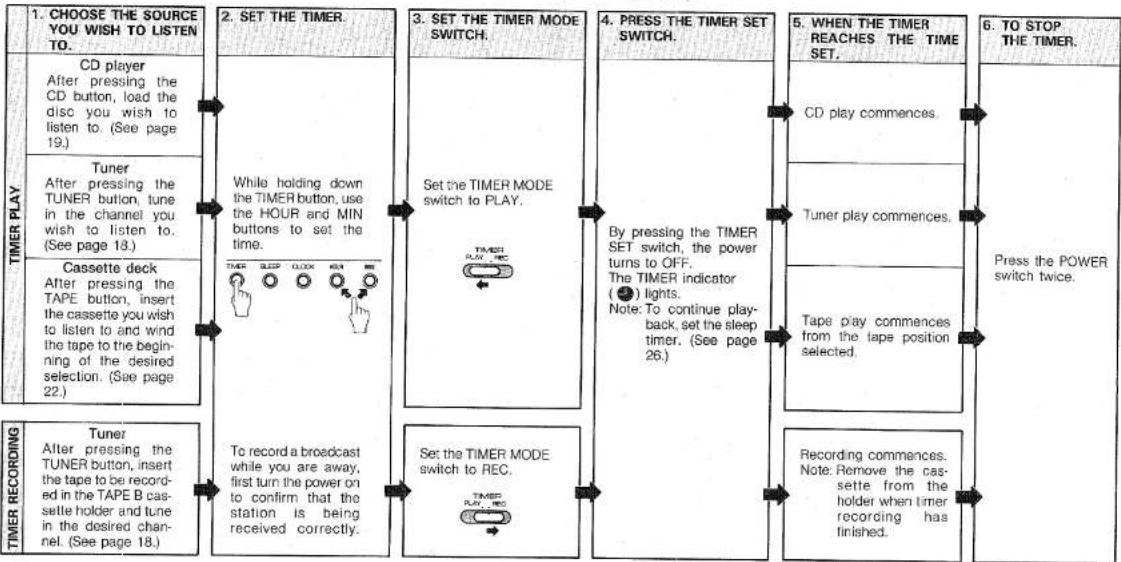
flowchart
graph LR
    A["1. CHOOSE THE SOURCE YOU WISH TO LISTEN TO."] --> B["CD player After pressing the CD button, load the disc you wish to listen to. (See page 19.)"]
    B --> C["Tuner After pressing the TUNER button, tune in the channel you wish to listen to. (See page 18.)"]
    C --> D["Cassette deck After pressing the TAPE button, insert the cassette you wish to listen to and wind the tape to the beginning of the desired selection. (See page 22.)"]
    D --> E["Tuner After pressing the TUNER button, insert the tape to be recorded in the TAPE B cassette holder and tune in the desired channel. (See page 18.)"]

    F["2. SET THE TIMER."] --> G["While holding down the TIMER button, use the HOUR and MIN buttons to set the time."]
    G --> H["To record a broadcast while you are away, first turn the power on to confirm that the station is being received correctly."]

    I["3. SET THE TIMER MODE SWITCH."] --> J["Set the TIMER MODE switch to PLAY."]
    J --> K["To record a broadcast while you are away, first turn the power on to confirm that the station is being received correctly."]

    L["4. PRESS THE TIMER SET SWITCH."] --> M["By pressing the TIMER SET switch, the power turns to OFF. The TIMER indicator (●) lights. Note: To continue play-back, set the sleep timer. (See page 26.)"]
    M --> N["To record a broadcast while you are away, first turn the power on to confirm that the station is being received correctly."]

    O["5. WHEN THE TIMER REACHES THE TIME SET."] --> P["CD play commences."]
    P --> Q["Tuner play commences."]
    Q --> R["To record a broadcast while you are away, first turn the power on to confirm that the station is being received correctly."]

    S["6. TO STOP THE TIMER."] --> T["Press the POWER switch twice."]
    T --> U["Recording commences. Note: Remove the cassette from the holder when timer recording has finished."]
- Timer memory
Unless power is interrupted or the AC cord is unplugged, the last timer setting remains in memory until a new time is set.
- Confirming the timer setting
Press the TIMER button.
- Turning the timer off
- Press the TIMER SET switch a second time. The timer indicator goes out. (The timer can also be turned off by pressing the POWER switch a second time.)
-
Timer play shuts off automatically after 60 minutes. (This also applies to tape play; the player shuts off automatically after 60 minutes even if there is tape remaining.)
-
During timer recording, the player shuts off automatically after 60 minutes even if the tape is less than 60 minutes long. If the tape is longer than 60 minutes, the player shuts off anyway after 60 minutes have elapsed.
- CD timer play
If the ⚪ mark lights during timer play, play will continue automatically if a new disc is inserted and the holder closed.
TROUBLESHOOTING
If your unit fails to operate normally, check the following points to determine whether the fault can be corrected by the simple measures suggested. If it cannot, or if the fault is not listed in the SYMPTOM column, disconnect the power cord and contact your dealer or service center for help.
| SYMPTOM | CAUSE | REMEDY | |
| AMPLIFIER | No power even if the POWER switch is pressed. | AC cord not plugged in. | Plug in AC cord. |
| No sound from one speaker. | BALANCE slider is all the way to the right or left. (★ YST-C30 only) | Adjust BALANCE slider. | |
| Loose speaker connections. | Connect properly. | ||
| TUNER | Excessive static in FM broadcasts. | Interference from starting motor of nearby car. | Position the FM antenna as high and as far away from nearby roads as possible. Connect using a coaxial cable. |
| Interference from thermostat of nearby electrical appliance. | |||
| Noise increases during stereo broadcasts. | Antenna input is too weak due to obstructions or excessive distance from broadcasting station. | Check antenna connections. | |
| Install a multi-element type FM antenna if possible. | |||
| Stereo broadcasts are noisy and STEREO indicator blinks on and off. | Insufficient antenna input. | Install an antenna appropriate for the electric field strength of your area. | |
| Cannot select preset stations. | Preset memory has been erased. | Reprogram memory presets. | |
| Buzzing or static during AM broadcasts. | Interference from source such as lightning, fluorescent lights, electric motors or thermostat of nearby electrical appliance. | Problem is difficult to eliminate but can be lessened by grounding indoor AM antenna. | |
| TV or microprocessor is being used nearby. | Move away from TV or microprocessor. | ||
| AM broadcast sensitivity is poor. | Radio signal is weak or antenna is not properly connected. | Properly connect AM loop antenna. | |
| Change orientation of AM loop antenna. | |||
| Install an external AM antenna. | |||
| Can't set timer. | Current time not set. | Set current time. | |
| Timer doesn't function as expected. | Power turned off using POWER switch. | After setting timer, turn power off using TIMER SET switch. | |
| CD PLAYER | Won't play even if disc is loaded. | Disc is upside down. | Load disc label side up. |
| Disc is dirty. | Clean disc. | ||
| No sound. | Input selector setting is incorrect. | Press input selector CD button. | |
| Sound stops suddenly (always at same spot). | Disc is dirty.Volume set too high. | Clean disc.Lower volume. | |
| CASSETTE DECK | Tape won't move during playback or recording. | Slack tape wrapped around pinch roller. | Take up slack with a pencil before using. |
| Can't record. | Erasure prevention tab broken off. | Replace cassette or cover erasure prevention hole with cellophane tape. | |
| Head is dirty. | Clean heads. | ||
| Sound is distorted or fades out. | Head is dirty. | Clean heads. | |
| Head has become magnetized. | Demagnetize heads with head eraser. | ||
| Tape is worn. | Replace cassette. | ||
| Poor sound quality. | TAPE selector or DOLBY NR selector is set to wrong position. | Set to positions matching those used when tape was recorded. | |
| Stereo balance is poor. | Head is dirty. | Clean heads. | |
| Excessive noise. | Head is dirty. | Clean heads. | |
| Head has become magnetized. | Demagnetize heads with head eraser. | ||
| Tape is worn. | Replace cassette. | ||
| Tape travel stops in middle of playback or recording. | Slack tape coming out of cassette shell. | Take up slack by turning reels with a pencil. | |
| Tape is creased or torn. | Replace with new cassette. | ||
| Endless tape is being used. | Don't use endless tapes. | ||
| Can't find specific selections on tape. | Silent gaps between selections are too short. | The music search function won't operate unless the silent gaps between selections are at least four seconds long. | |
| Excessively soft passages in middle of selections. | |||
| Speaking voice recorded on tape off the air, etc. | |||
| REMOTE CONTROL | Remote control doesn't work. | Batteries are dead. | Replace batteries. |
| Remote control is too far away or is being used at Incorrect angle. | Use within 6 m (23.6 ft) and 20° radius. | ||
| TV functions strangely when the remote control is used. | Remote control is being used near TV set with infrared photo sensor. | Move TV farther away or cover its infrared photo sensor. |
SPECIFICATIONS
• AMPLIFIER SECTION:
Rated output power (1kHz, 6 ohms, 0.5% THD) ★ YST-C30/☆ YST-C10....24W × 2
Total harmonic distortion (15W, 6 ohms, 1 kHz) 0.06%
Input sensitivity (AUX) 250mV Dynamic sound 100Hz/+5dB
10kHz/+3dB Headphone output (16 ohms, 40Hz\~20kHz, -3dB)....300mV
• GRAPHIC EQUALIZER:
Center frequencies..... 100Hz, 500Hz, 2kHz, 10kHz Adjustable range..... ±8dB
• TUNER/TIMER SECTION:
Tuning frequency range FM section 87.5MHz \~ 108MHz
AM or MW section U.S.A and Canadian models .... 530kHz \~ 1720kHz U.K. and European models .... 522kHz \~ 1620kHz Regular models.... 531kHz \~ 1602kHz (9kHz step) 530kHz \~ 1610kHz (10kHz step)
Australian models 531kHz\~1602kHz LW section
(U.K. and European models) ..... 153kHz - 281kHz Auto tuning ..... 153kHz - 279kHz
Timer PLAY/REC..... once per day, 60 minutes. Sleep..... 3 hours 45 minutes max.
• CASSETTE DECK SECTION:
Recording/playback frequency response (chrome tape).... 40Hz\~16kHz, ±3dB Signal to noise ratio (DOLBY B ON).... 65dB Wow and flutter .... ±0.08% (W.R.M.S)
• CD PLAYER SECTION:
Dynamic range 88dB Signal to noise ratio 90dB Filter 16 bit digital filter +3rd order active filter. Distortion (1kHz) 0.09%
- SPEAKER SYSTEM:
Type ★ YST-C30....2way, AS type, magnetically shielded. ☆ YST-C10....Full-range AS Type
Speaker units ★ YST-C30
Woo'er 12cm polypropylene cone type (JA1227)
Tweeter 2cm soft dome type (JA05B1)
Crossover frequency....4kHz ☆YST-C10....12cm polypropylen
cone type (JA1268) Efficiency 87dB/W/m
Frequency response ★ YST-C30 35Hz - 20kHz
☆ YST-C10 40Hz\~18kHz
GENERAL:
Power supply voltage U.S.A and Canadian models....AC120V, 60Hz European models....AC220V, 50Hz U.K. and Australian models....AC240V, 50Hz Regular models....AC110/120/220/240V, 50/60Hz
Power consumption U.S.A models 95W Canadian models 145W European models 250W U.K. and Australian models 250W Regular models 250W
Dimensions (W × H × D) Main unit ★ YST-C30/★ YST-C10
U.S.A, Canadian and Regular models 300 × 268 × 294mm
(11-13/16" × 10-9/16" × 11-9/16") U.K., European and Australian models
300 × 268 × 299mm (11-13/16" × 10-9/16" × 11-3/4")
Speaker (single) ★ YST-C30 ..... 324 × 232 × 232mm (12-3/4" × 9-1/8" × 9-1/8")
☆ YST-C10 ... 150×217.5×242mm
(5-7/8"×8-9/16"×9-1/2")
Weight
Main unit ★ YST-C30/☆ YST-C10 . 7.5kg (16 lbs 8 oz) Speaker (single) ★ YST-C30..... 4.3kg (9 lbs 7 oz) ☆ YST-C10..... 2.3kg (5 lbs 1 oz)
- ACCESSORIES:
(Included with the ★ YST-C30/☆ YST-C10)
★☆ Remote control (VH34720)....1 pc.
★☆ AAA batteries (UM-4) 2 pcs.
★☆ AM Loop antenna 1 pc.
★☆ FM Wire antenna (Regular, German and Italian models only).... 1 pc.
★☆ Rod Antenna (U.S.A, Canadian, Australian, U.K. and European-except German and Italian-models only).... 1 pc.
★☆ Antenna holder (-ditto-).... 1 pc.
★☆ Screws (-ditto-).... 3 pcs.
★☆ Connection wire (-ditto-).... 1 pc.
★☆ Converter plug (U.K. and European
models only) 1 pc.
★☆ Speaker cables (with connectors)....2 pcs.
(Included with the YST-C10 only)
☆ Speaker attachment fittings.... 2 pcs.
☆ Screws 4 pos.
Specifications are subject to change without notice due to product improvements.
★ YST-SC30 only
* This speaker system is designed to allow use near a TV set. Depending on the placement, however, there may be cases where the color of the TV picture is affected. Should this happen, turn off the TV set for 15–30 minutes.
Then turn it on again. The TV's built-in demagnetization function will correct the effect of the speakers on the picture. Should the problem continue unabated, move the speakers further away from the TV set.
* If placed near a magnet or other object which generates magnetic flux, the color of the TV picture may be affected due to the combined effect with this speaker system. Please keep this in mind when deciding on speaker placement.
DOLBY SYSTEM®
Dolby and the double D mark are trademarks of Dolby Laboratories Licensing Corp. Dolby noise reduction system manufactured under license from Dolby Laboratories Licensing Corp.
YAMAHA
YAMAHA ELECTRONICS CORPORATION, USA 6722 ORANGETHORFE AVE. BUENA PARK CALE 90630 USA
YAMAHA CANADA MUSIC LTD. 135 MI NER AVE, SCARBOROUGH, ONTARIO M15 3R1, CANADA
YAMAHA ELECTRONIK EUROPA G.m.b.H. 2004 RELLINGEN, HEI HAMBURQ, SIEMENSSTR. 22/04, E.R. OF GERMANY
YAMAHA ELECTRONICIUE FRANCE S.A. 17 RUE DES CAMPANULES, LOGNES 77321 MARNE LA VALLEE CEDEX 2, FRANCE
YAMAHA ELECTRONICS (UK) LTD. YAMAHA HOUSE, 200 RICKMANSWORTH ROAD WATFORD, HERIS WD1 7JS, ENGLAND
YAMAHA SCANDINAVIA A.B. J A WETTERGRENS GATA 1, BOX 300531, 400 43 VASTRA FROLLINDA, SWEDEN YAMAHA MUSIC AUSTRALIA STX LTD., 17-22 MARKET ST., SOUTH AVESLEY, CO., NORTANA
TAMAHA MUSIC AUSTRALIA PTE, LTD. 1730 MARKET ST., SOUTH MELBOURNE 3205 WC., AUSTRALIA
YAMAHA CORPORATION
VI 61510-0 BWgw.g Printed in Japan
- YAMAHAYST-C30/C10
- CENTER
- CONTENTS
- OWNER'S MANUAL
- IMPORTANT!
- Model: YST-C30/YST-C10
- WARNING
- SAFETY INSTRUCTIONS
- CAUTION: READ THIS BEFORE OPERATING YOUR UNIT.
- DANGER
- CAUTION
- MAJOR DIFFERENCE BETWEEN THE YST-C30 AND YST-C10
- ACCESSORIES
- SPEAKER PLACEMENT FOR YST-C30:
- ATTACHING AND REMOVING SPEAKERS (☆ YST-C10 only)
- ■ Speaker attachment
- ■ Speaker removal
- THE ACTIVE SERVO TECHNOLOGY SYSTEM
- ■ Fold-out legs
- CONNECTIONS
- ■ ANTENNA CONNECTIONS
- AM antenna
- Connecting the included FM antenna:
- U.S.A., Canadian, Australian, and Regular models
- Connecting an external FM antenna:
- ■ SPEAKER SYSTEM CONNECTIONS
- ■ EXTRA SPEAKER CABLE
- ■ CONNECTING EXTERNAL COMPONENTS
- Notes:
- NAMES AND FUNCTIONS OF PARTS
- ■ TUNER/AMPLIFIER SECTION (See Fig. 2)
- ■ TIMER SECTION (See Fig. 2)
- TO CONFIRM TIMER SETTINGS
- ■ CD PLAYER SECTION (See Fig. 4)
- ■ CASSETTE DECK SECTION (See Fig. 1)
- REMOTE CONTROL
- ■ REMOTE CONTROL OPERATION
- ■ REMOTE CONTROL NUMERIC KEYPAD
- ■ BATTERY INSTALLATION AND REPLACEMENT
- VOLUME AND TONE ADJUSTMENTS
- ■ ADJUSTING THE VOLUME
- ■ LISTENING AT LOW VOLUME
- ■ ADJUSTING THE VOLUME USING THE REMOTE CONTROL
- ■ LISTENING WITH HEADPHONES
- ■ ADJUSTING THE TONE
- LISTENING TO RADIO BROADCAST
- ■ AUTO STATION SELECTION
- ■ MANUAL STATION SELECTION
- • The station frequency display
- ■ PROGRAMMING THE MEMORY
- - Changing the stations programmed in memory
- ■ SELECTING A PRESET STATION
- - Listening to FM stereo broadcasts
- NOTES ABOUT HANDLING COMPACT DISCS
- PLAYING COMPACT DISCS
- ■ PLAY AND BASIC OPERATIONS
- PAUSING PLAY
- STOPPING PLAY
- MUSIC CALENDAR
- ■ PROGRAMMING TRACKS
- ■ PROGRAM PLAY
- TO CHECK THE ORDER OF TRACKS
- CANCELING THE CURRENT PROGRAM
- DISCS CONTAINING MORE THAN 20 TRACKS
- REPEATING THE ENTIRE DISC
- REPEATING A PROGRAMMED SEQUENCE OF TRACKS
- STOPPING REPEAT PLAY
- ■ LISTENING TO THE FIRST PART OF EACH TRACK ON THE DISC (INTRO PLAY)
- STOPPING INTRO PLAY
- ■ PROGRAMMING THE MEMORY DURING INTRO PLAY (INTRO PROGRAM SELECTION)
- STOPPING INTRO PROGRAM SELECTION
- ■ DISPLAY FUNCTIONS
- WHEN NO CD IS PLAYING
- DURING PLAY
- NOTES ABOUT HANDLING CASSETTE TAPES
- • Protecting your recordings
- - Taking up slack in the tape
- - Storing cassettes
- CASSETTE TAPE PLAY
- STOPPING TAPE PLAY
- ■ SEARCHING FOR THE BEGINNING OF A SELECTION (FIND BEGINNING PLAY)
- ■ SKIPPING BACK TO THE BEGINNING OF THE SELECTION CURRENTLY IN PLAY
- ■ FAST FORWARD/REWIND
- ■ REVERSE MODE AND CONTINUOUS PLAY
- CONTINUOUS PLAY USING BOTH TAPE A AND TAPE B
- RECORDING
- TO TEMPORARILY PAUSE RECORDING
- TO STOP RECORDING
- TO MONITOR THE SIGNAL BEING RECORDED
- THE TAPE COUNTER
- ■ RECORDING FROM CD
- CD REPLAY RECORDING
- (Example)
- End of front side encountered in middle of third track
- ■ RECORDING FROM AN EXTERNAL COMPONENT
- EQ REC (EQUALIZER RECORDING) (\*YST-C30 ONLY)
- TAPE EDITING (DUBBING)
- • Before starting tape editing
- ■ IF THE TAPES IN THE PLAY AND THE RECORD SIDES ARE OF DIFFERENT LENGTHS
- ■ USING DIFFERENT TAPE TYPES FOR TAPE A AND TAPE B
- USING THE TIMER
- SETTING THE CURRENT TIME
- SLEEP TIMER
- WAKE UP TIMER (TIMER PLAY) AND TIMER RECORDING
- TROUBLESHOOTING
- SPECIFICATIONS
- • AMPLIFIER SECTION:
- • GRAPHIC EQUALIZER:
- • TUNER/TIMER SECTION:
- • CASSETTE DECK SECTION:
- • CD PLAYER SECTION:
- - SPEAKER SYSTEM:
- GENERAL:
- Weight
- - ACCESSORIES:
- ★ YST-SC30 only
- DOLBY SYSTEM®
- YAMAHA
Marke : YAMAHA
Modell : YST-C30
Kategorie : Hi-Fi-System